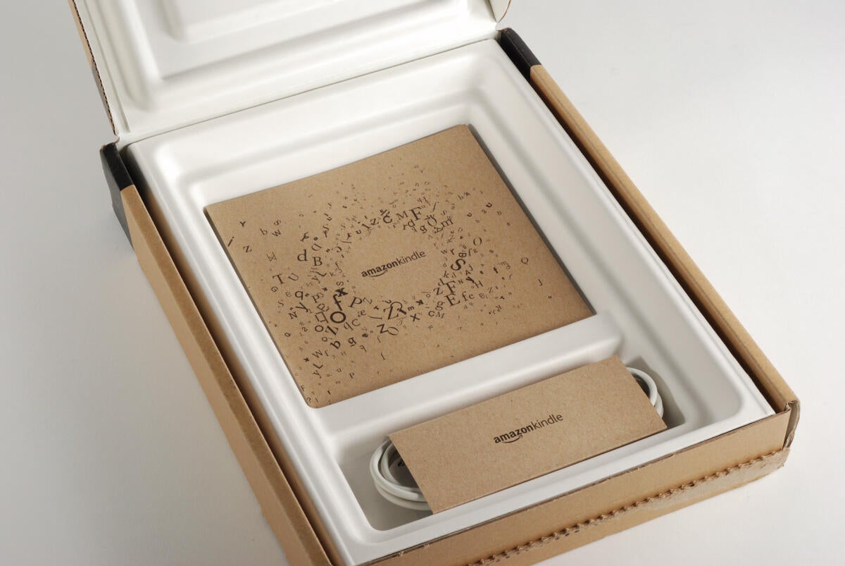
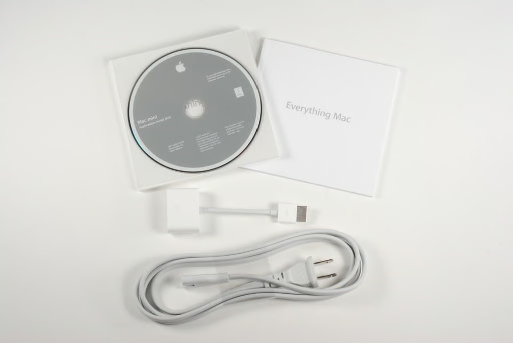
Under the Kindle DX, you’ll find the product documentation and power cable.
Photo credit: Bill Detwiler / TechRepublic
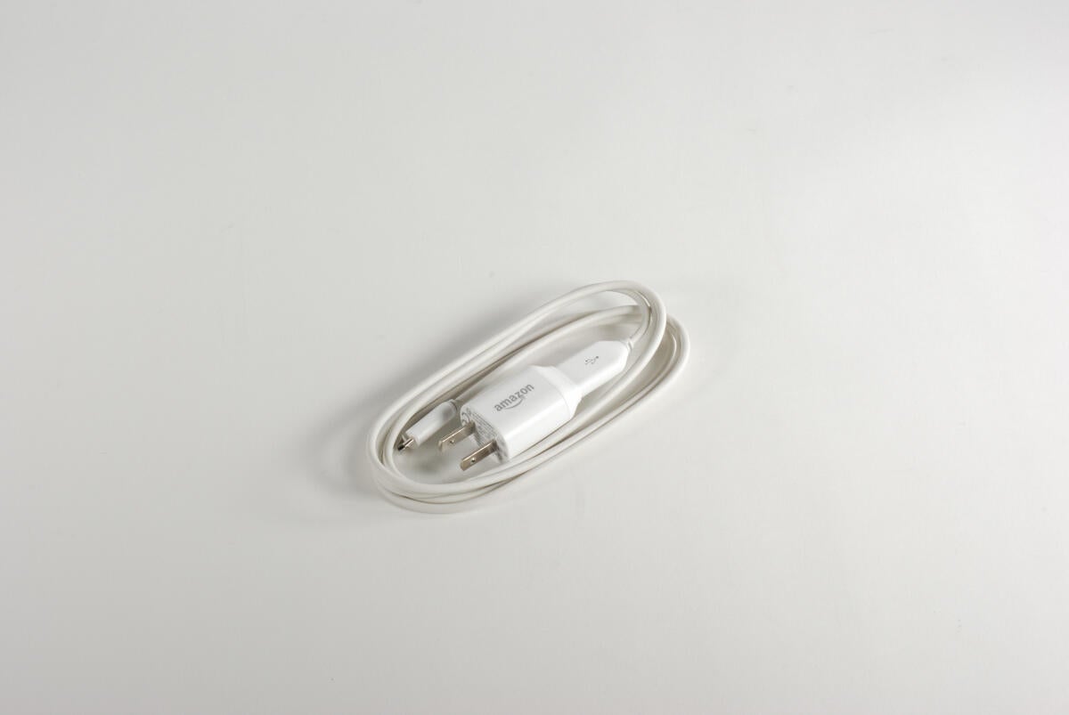
The power cable on the Kindle DX (Graphite) appears to be identical to the one used on the previous Kindle DX.
Photo credit: Bill Detwiler / TechRepublic

Along the right side of the Kindle DX (Graphite) are the Volume up/down, Home, Menu, Back, Next Page, and Previous Page buttons. The 5-way controller is also located on the right side.
Photo credit: Bill Detwiler / TechRepublic
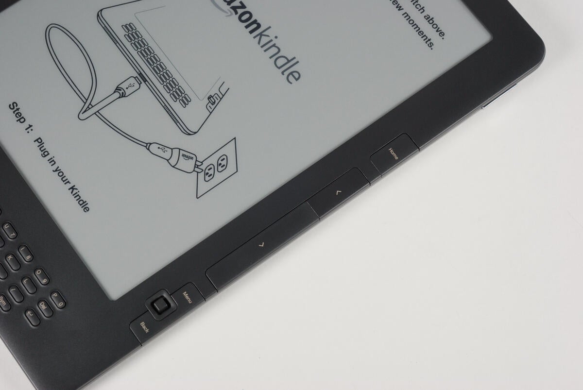
The new Kindle’s control buttons are the same as the ones on the original device.
Photo credit: Bill Detwiler / TechRepublic
Using a thin metal spludger, you can release the two tabs that snap the plastic window to the rest of the Kindle DX (Grpahite).
Photo credit: Bill Detwiler / TechRepublic
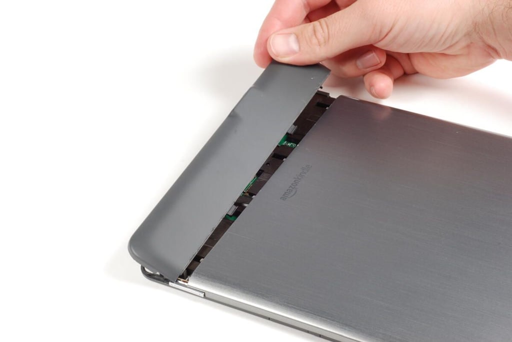
Once you depress the two plastic tabs (shown here), you should be able to slide the plastic panel forward.
Photo credit: Bill Detwiler / TechRepublic
Behind the RF window is the antenna for the Kindle DX’s 3G wireless card.
Photo credit: Bill Detwiler / TechRepublic
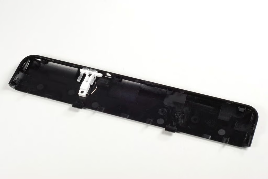
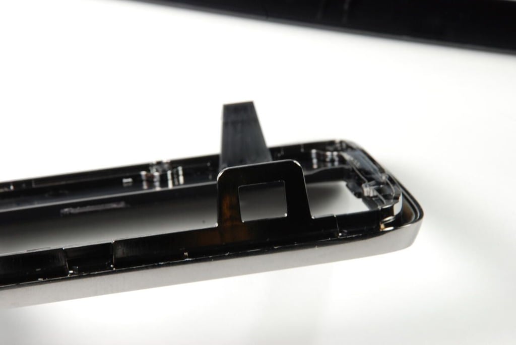
The external portion of the Kindle DX’s power switch is attached to the plastic RF window.
Photo credit: Bill Detwiler / TechRepublic
There are two small Phillips screws that hold the back metal panel in place–one on each side. You’ll need to remove both before the metal panel will come free.
Photo credit: Bill Detwiler / TechRepublic
Lifting away the metal panel from the back of the Kindle DX (Graphite), we can see the 3G wireless card and a little of the main logic board.
Photo credit: Bill Detwiler / TechRepublic
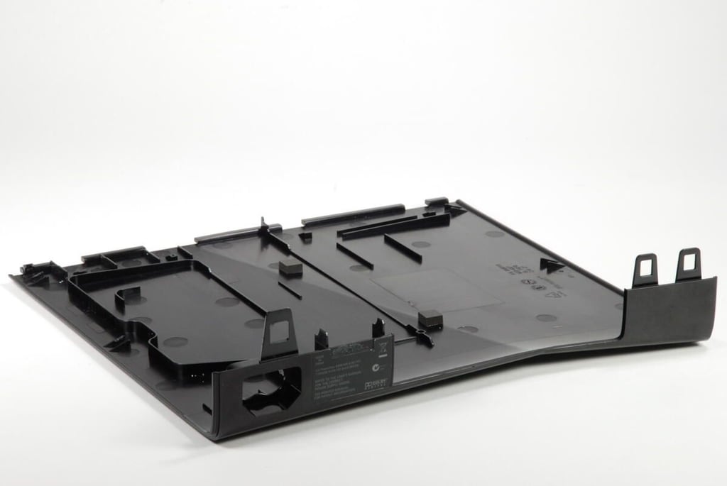
Photo credit: Bill Detwiler / TechRepublic
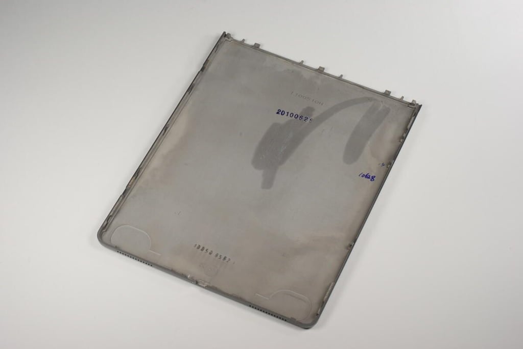
Photo credit: Bill Detwiler / TechRepublic
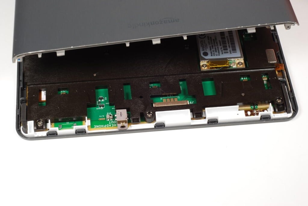
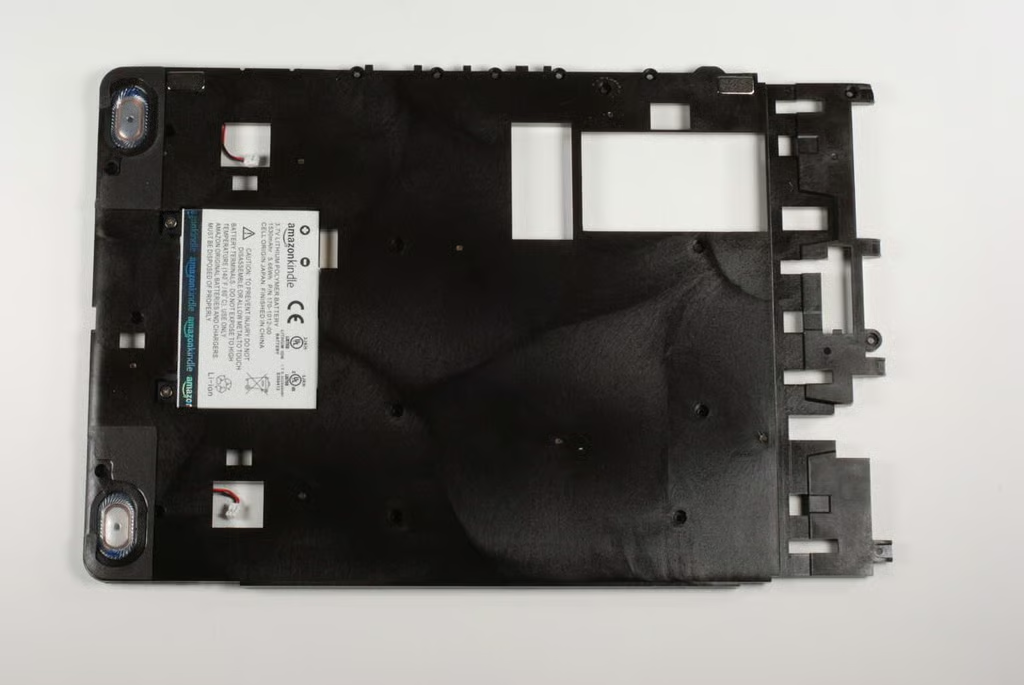
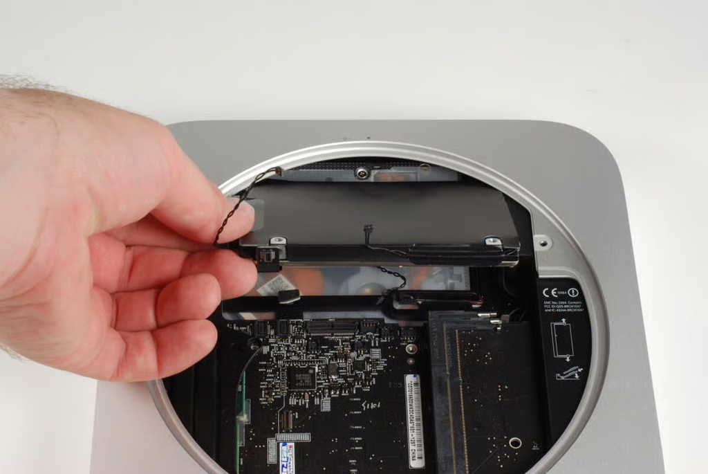
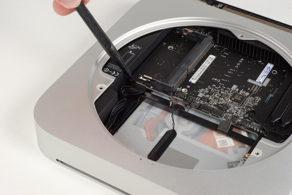
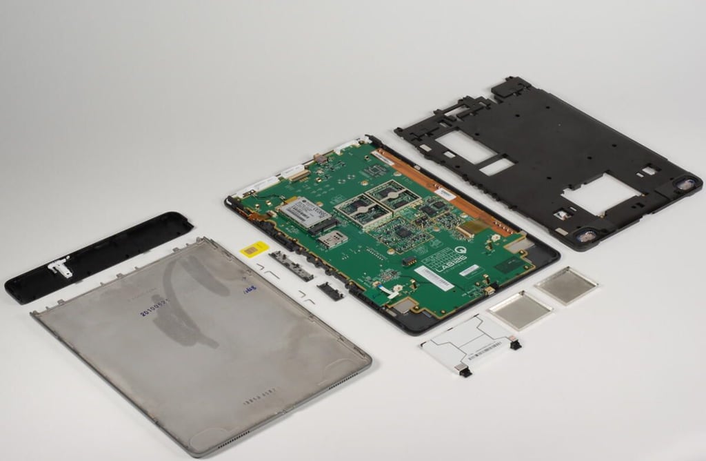
With the metal removed from the back of the Kindle DX (Graphite), we get our first look inside Amazon’s wireless reader. Unfortunately, a large plastic support structure, covers most of the main logic board. At this point, all we can really see are the battery, 3G wireless card, and SIM card.
To remove support structure, you’ll need to remove 20 Phillips screws that hold it to the front case panel and logic board. You can leave the two screws holding the battery in place. We’ll remove those later. You will also need to disconnect the two molex connectors that connect the speakers to the main logic board.
Photo credit: Bill Detwiler / TechRepublic
The battery will come away with the support structure.
Photo credit: Bill Detwiler / TechRepublic
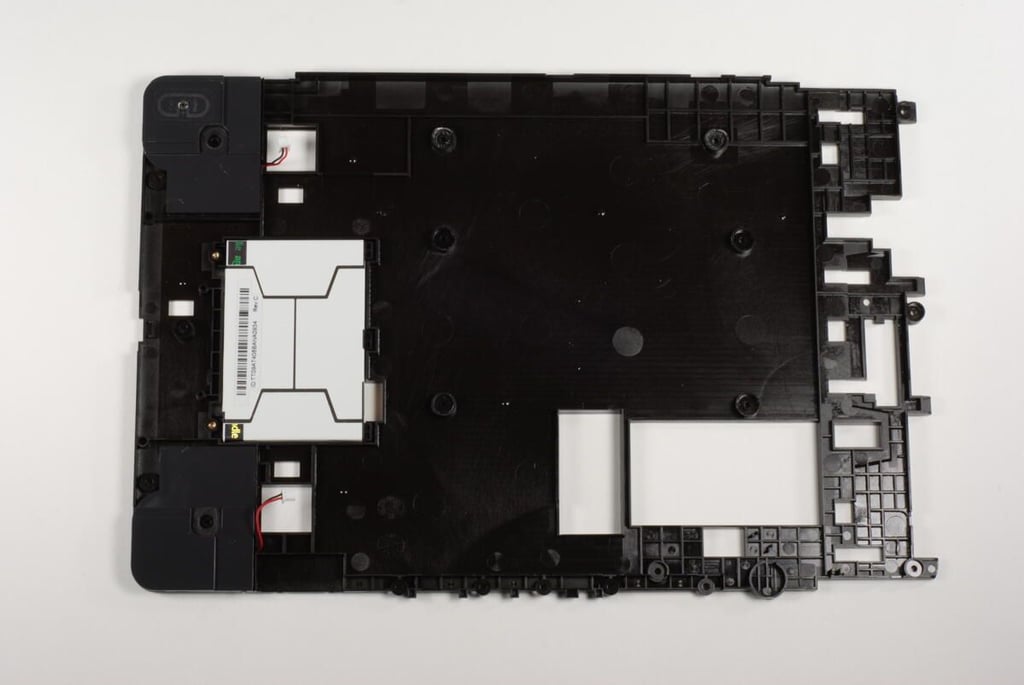
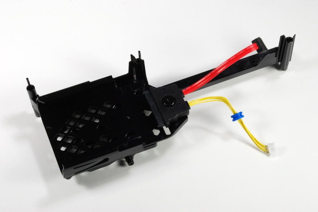
The back of the large, plastic support structure. You can now remove the two screws holding the battery in place.
Photo credit: Bill Detwiler / TechRepublic
As with the original Kindle DX’s main logic board, the Graphite version’s board has marking for Lab126–the company that designed and developed the Kindle for Amazon.
Photo credit: Bill Detwiler / TechRepublic
The 5-way controller is connected to the Kindle DX’s main logic board by a thin ribbon cable. The connector is marked with “JOYSTICK ASSY”. Below the ribbon cable is one of the DX’s two molex speaker connectors.
Photo credit: Bill Detwiler / TechRepublic
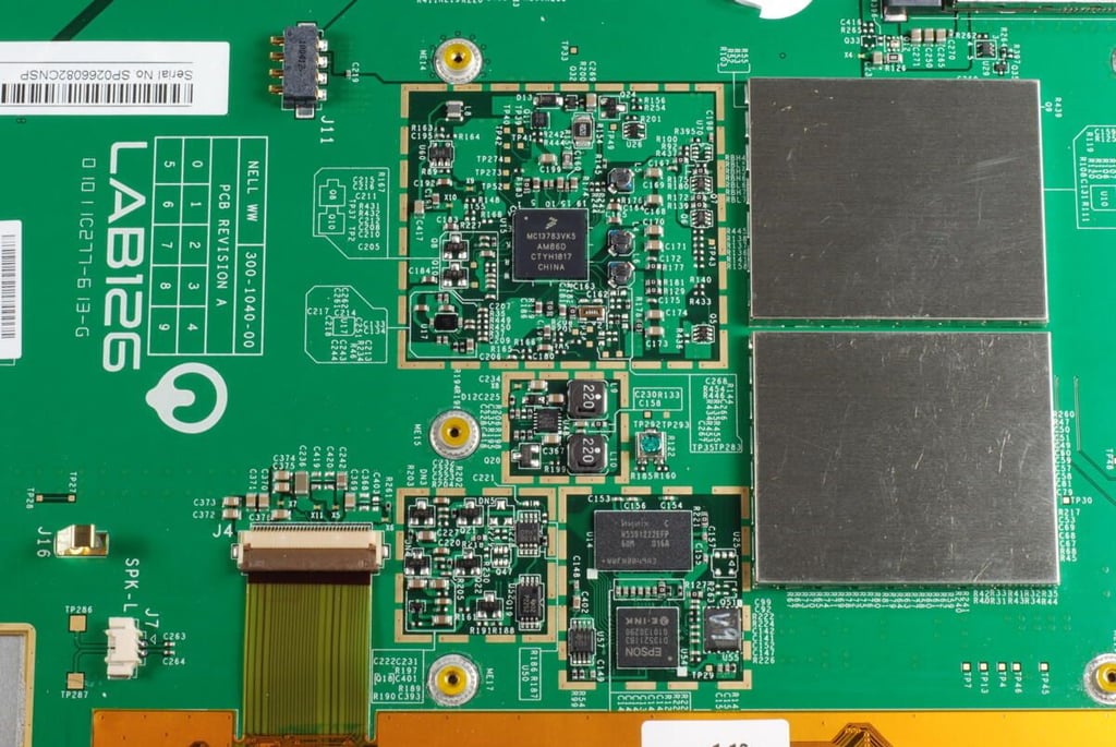
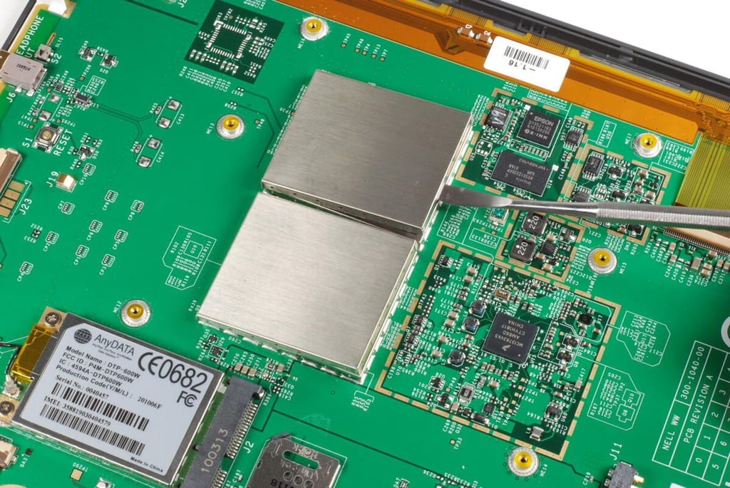
Clustered together are the main chips for the Kindle DX–some still hidden behind metal shields. The display’s thin ribbon cable is also located here.
Photo credit: Bill Detwiler / TechRepublic
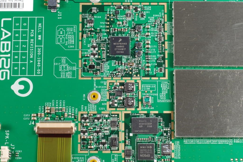
Several chips are visible within this cluster, including:
Freescale Semiconductor MC13783 Power Management and Audio Circuit
Hynix H55S1222EFP-60M 128M (4Mx32bit) Mobile SDRAM
EPSON E-Ink controller (D135211B3)
Photo credit: Bill Detwiler / TechRepublic
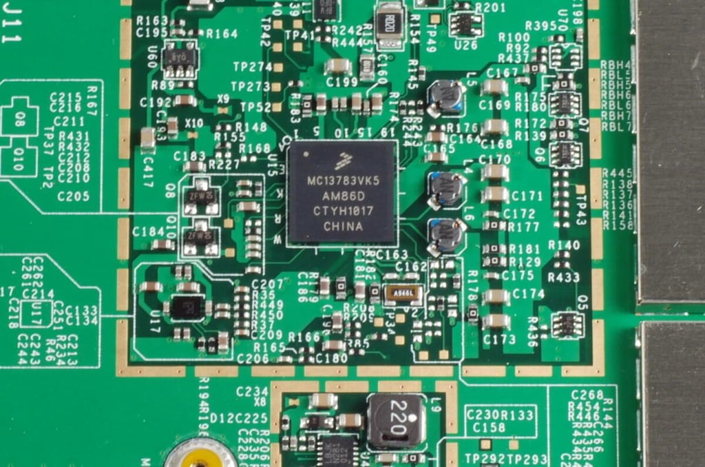
Freescale Semiconductor MC13783 Power Management and Audio Circuit
Photo credit: Bill Detwiler / TechRepublic
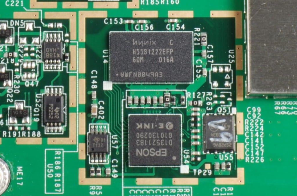
Hynix H55S1222EFP-60M 128M (4Mx32bit) Mobile SDRAM
EPSON E-Ink controller (D135211B3)
Photo credit: Bill Detwiler / TechRepublic
The Kindle DX (Graphite) uses an AnyDATA DTP-600W HSPA mini PCI-E module for wireless connectivity. According to AnyDATA documentation the DTP-600W “operates globally on tri-band UMTS 850/1900/2100 wireless networks as well as quad-band GSM/GPRS/EDGE 850/900/1800/1900 networks.”
Below the wireless module is a SIM card, which was not present on the original Kindle DX.
Photo credit: Bill Detwiler / TechRepublic
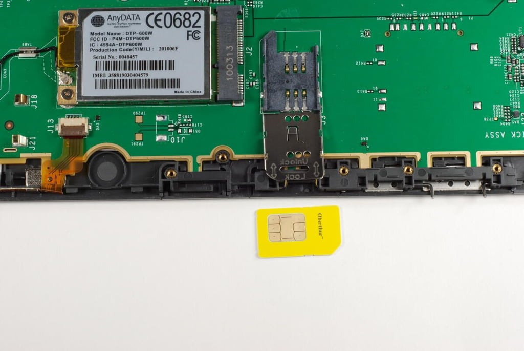
You can remove the SIM card on the Kindle DX (Graphite) by sliding the metal cover to the unlock position and lifting it up.
Photo credit: Bill Detwiler / TechRepublic
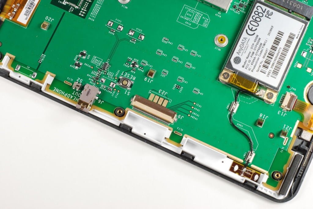
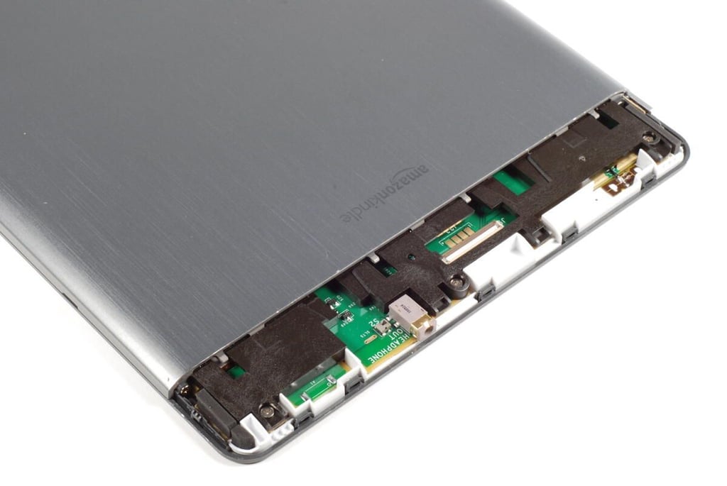
Along the top edge of the main logic board, we find the headphone jack, the 3G antenna, and an unused ribbon cable connector.
Photo credit: Bill Detwiler / TechRepublic
The Next Page and Previous Page buttons are held in place with small metal hinge pins.
Photo credit: Bill Detwiler / TechRepublic
To remove the page navigation buttons you simply pull out the hinge pins. There are no wires to disconnect.
Photo credit: Bill Detwiler / TechRepublic
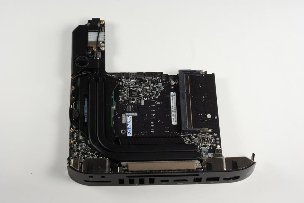
Photo credit: Bill Detwiler / TechRepublic
Using a metal spludger you can gently pry loose the thin metal shields that cover the CPU and other main chips.
Photo credit: Bill Detwiler / TechRepublic
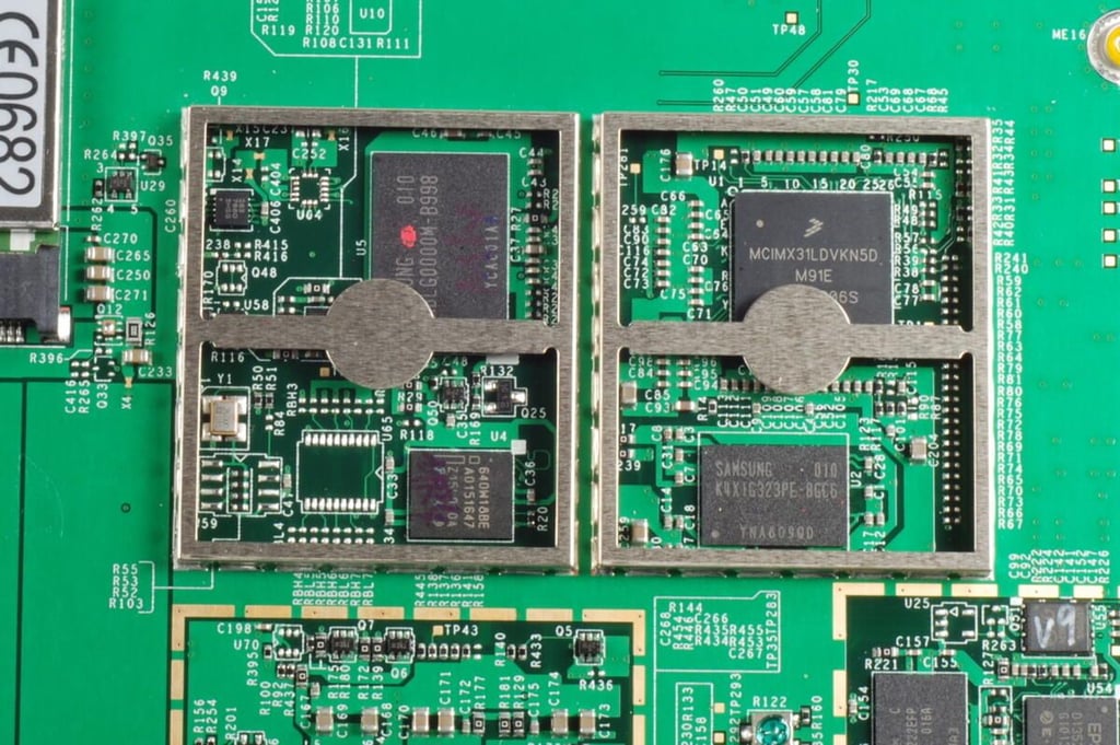
Beneath the metal shields are the heart of the Kindle DX (Graphite), including:
Freescale MCIMX31L Series 400 MHz SMT Multimedia Applications Processor
Samsung K4X1G323PE-8GC6 DRAM
Intel 640W18BE wireless FLASH memory
Samsung KMBLG0000M-B998 moviNAND
These chips are
Photo credit: Bill Detwiler / TechRepublic
The Kindle DX (Graphite) was rather easy to disassemble. The hardest step was removing the RF window without damaging the plastic window or metal panel.
Mounted under the main logic board is the E-Ink display. But as there’s not much to see on the back of the display and the logic board appears to be held in place by either glue or sticky tape, I’m going to refrain from pulling the board away from the front plastic case.
The new Kindle DX (Graphite) is nearly identical to the original version.
Photo credit: Bill Detwiler / TechRepublic
Bill Detwiler is the Editor for Technical Content and Ecosystem at Celonis. He is the former Editor in Chief of TechRepublic and previous host of TechRepublic's Dynamic Developer podcast and Cracking Open, CNET and TechRepublic's popular online show. Previously, Bill was an IT manager in the social research and energy industries. He has bachelor's and master's degrees from the University of Louisville, where he has also lectured on computer crime and crime prevention.


