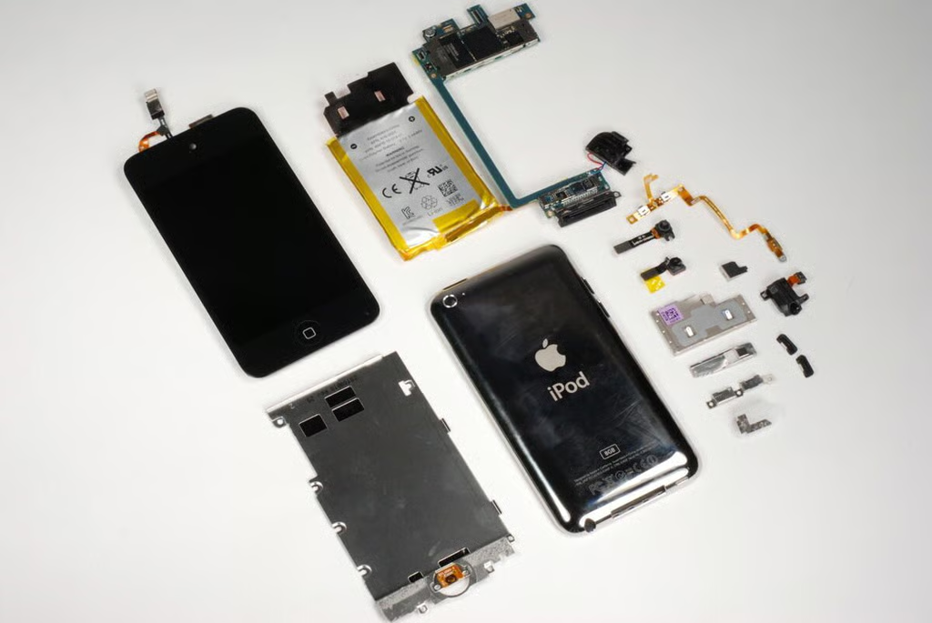
In September 2010, Apple unveiled the 4th generation iPod Touch. The new Touch is physically similar to previous versions, but it has several new features–including two cameras.
As with the iPod Shuffle and Nano, the Touch isn’t designed to be easily disassembled. In fact, I found it to be the most difficult to take apart.
To disassemble the iPod Touch, you’ll need a Phillips #00 screwdriver, a thin metal blade, plastic spudger, or iPod case opening tool, and a hair dryer or heat gun.
Photo by: Bill Detwiler / TechRepublic
Caption by: Bill Detwiler
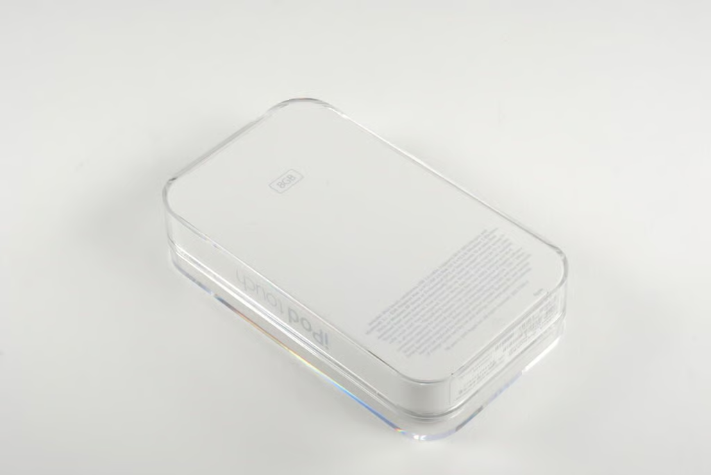
The 4th generation iPod Touch is available in three memory sizes (8GB, 32GB, and 64GB). The 8GB Touch sells for $229 (US), the 32GB version costs $299, and the 64GB Touch will set you back $399.
Photo by: Bill Detwiler / TechRepublic
Caption by: Bill Detwiler
Photo by: Bill Detwiler / TechRepublic
Caption by: Bill Detwiler
The 4th generation iPod Touch (left) is thinner than the iPhone 4 (center) and original iPhone (right).
Photo by: Bill Detwiler / TechRepublic
Caption by: Bill Detwiler
To begin disassembling the 4th generation iPod Touch, you’ll need to use a heat gun or hair dryer to heat the adhesive that holds the front glass panel and display to the metal case.
Photo by: Bill Detwiler / TechRepublic
Caption by: Bill Detwiler
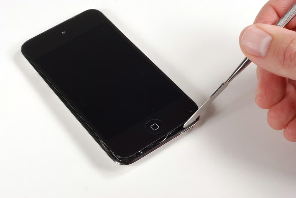
Once you’ve sufficiently warmed the adhesive, you can use a thin metal blade (shown here) or iPod Touch case opening tool to gently pry the front glass panel away from the metal case. WARNING: Be very careful not to insert the tool into the iPod Touch too far–especially along the sides. If you do, you could damage the display. You should really only pry the front panel from the bottom where the Home button is.
Photo by: Bill Detwiler / TechRepublic
Caption by: Bill Detwiler
Photo by: Bill Detwiler / TechRepublic
Caption by: Bill Detwiler
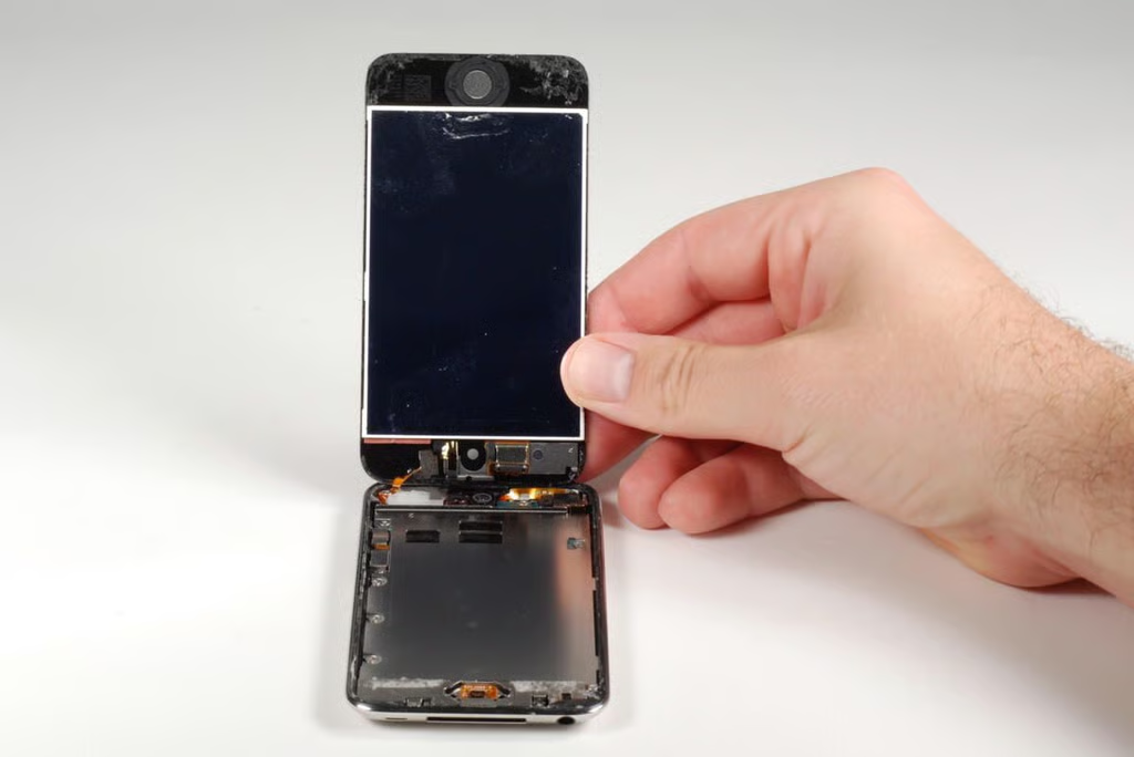
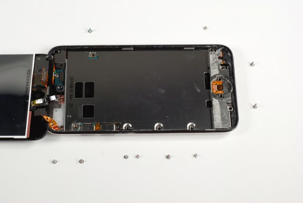
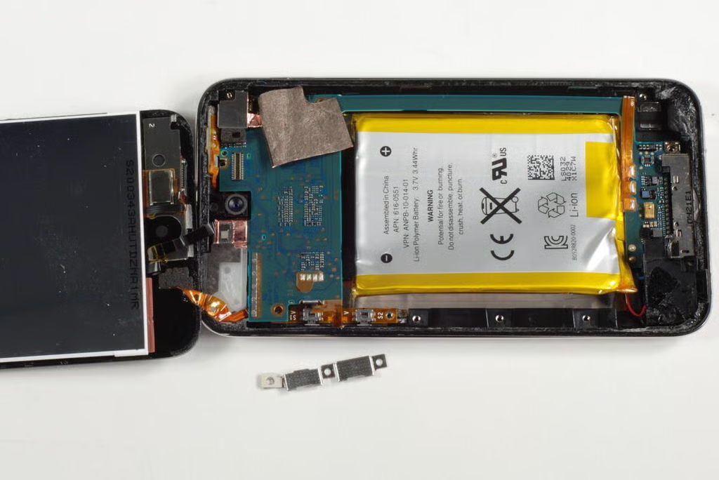
Once you’ve freed the front panel from the adhesive, you can lift it up from the metal case. Take care not to pull too hard. The front panel is still connected to the main logic board via several extremely thin ribbon cables.
Photo by: Bill Detwiler / TechRepublic
Caption by: Bill Detwiler
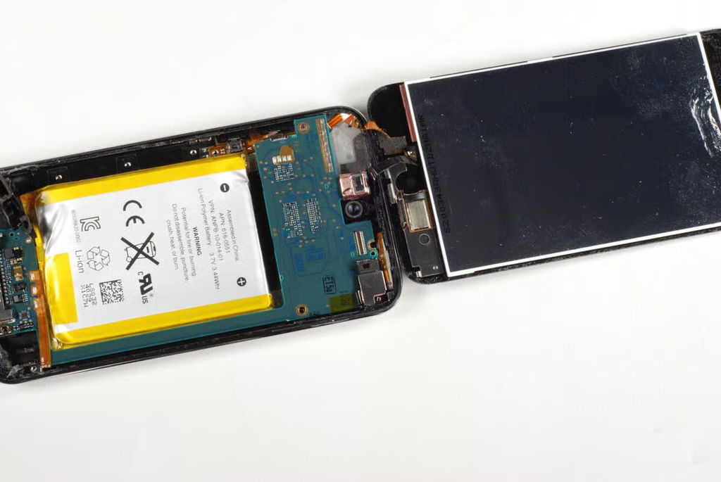
The 4th generation iPod Touch’s display is fused to the front glass panel. If you break the display, you’ll likely need to replace the entire panel. Unfortunately, several of the front panel’s ribbon cables are attached to the underside of the logic board.
Photo by: Bill Detwiler / TechRepublic
Caption by: Bill Detwiler
Before we can remove the logic board, we’ll need to remove the large, metal EMI shild that covers the battery and most of the board. At least 10 Phillips #00 screws of different lengths hold the shield to the case.
Photo by: Bill Detwiler / TechRepublic
Caption by: Bill Detwiler
Even with the screws removed, the EMI is difficult to pry loose. It is held in place with adhesive and small tabs along the side.
Photo by: Bill Detwiler / TechRepublic
Caption by: Bill Detwiler
A thin piece of copper foil holds the EMI shield to the iPod Touch’s logic board. So don’t just yank it free.
Photo by: Bill Detwiler / TechRepublic
Caption by: Bill Detwiler
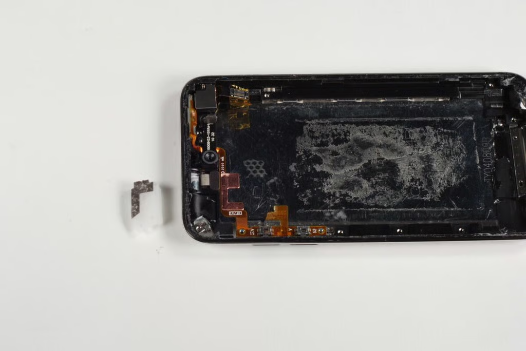
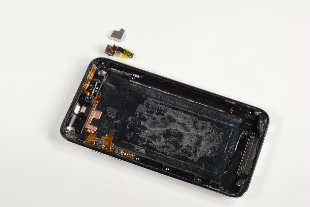
Well, this is a first. While removing the EMI shield, I apparently tore the very thin ribbon cable that connected the volume buttons to the logic board.
Photo by: Bill Detwiler / TechRepublic
Caption by: Bill Detwiler
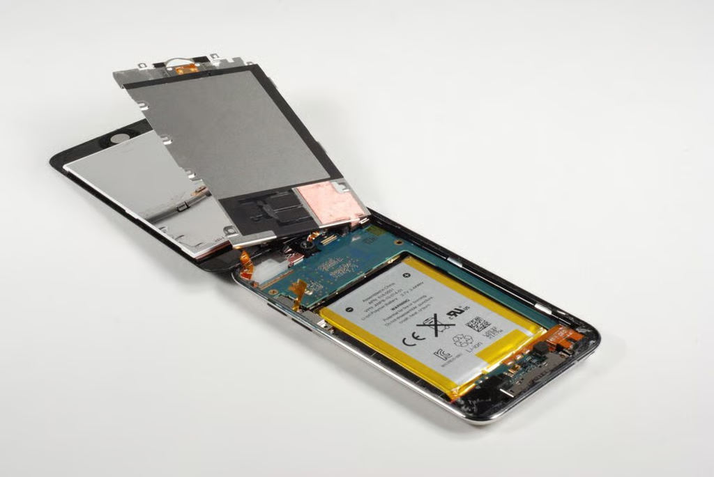
Photo by: Bill Detwiler / TechRepublic
Caption by: Bill Detwiler
The contact for the Home button is located at the bottom of the EMI shield.
Photo by: Bill Detwiler / TechRepublic
Caption by: Bill Detwiler
Photo by: Bill Detwiler / TechRepublic
Caption by: Bill Detwiler
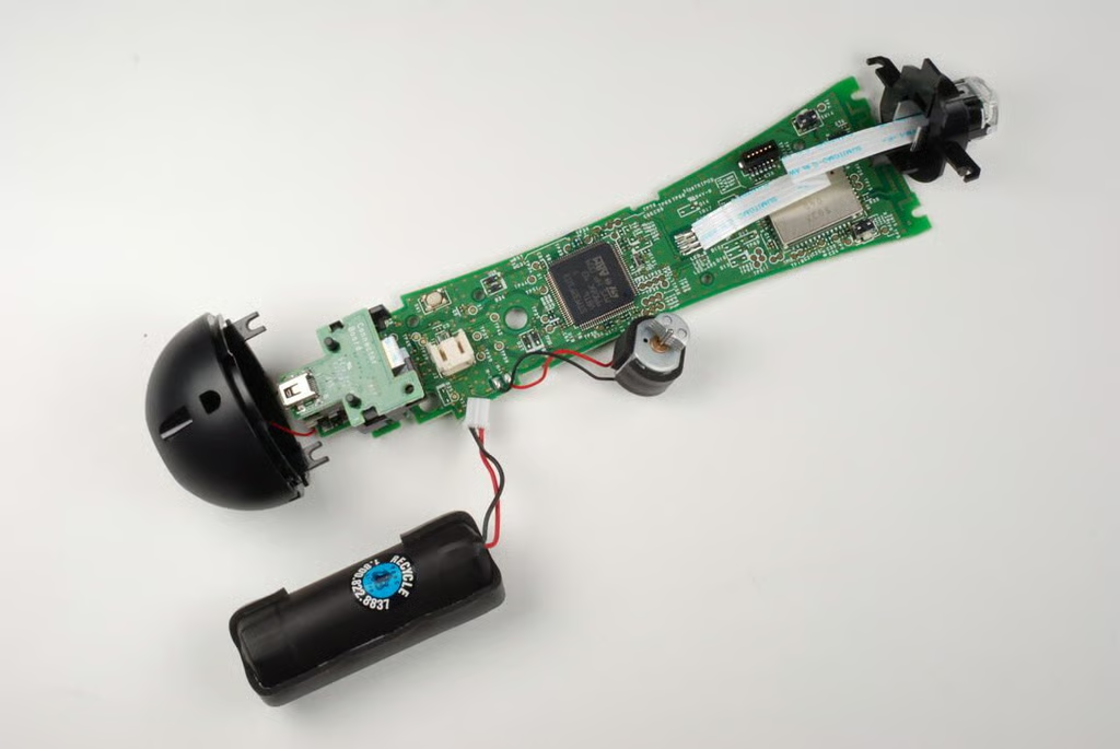
Photo by: Bill Detwiler / TechRepublic
Caption by: Bill Detwiler
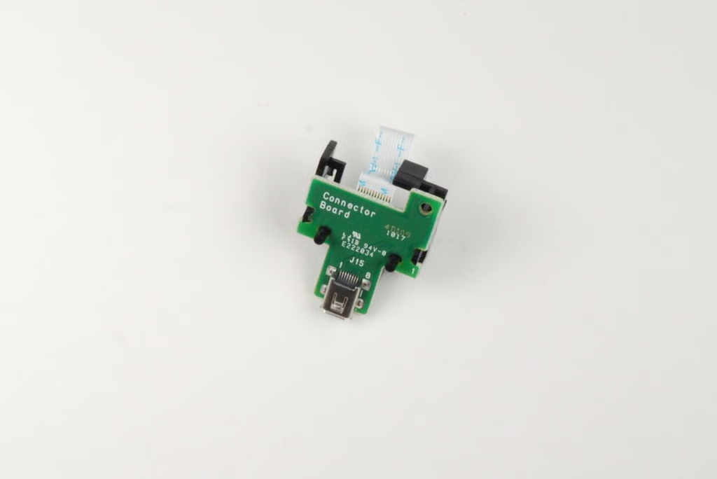
The front panel is attached to the main logic board by three ribbon cables. You can pop one of the connectors free without much effort, but removing the other two will require us to remove the logic board. The thin copper ribbon cable is likely the Wi-Fi antenna.
Photo by: Bill Detwiler / TechRepublic
Caption by: Bill Detwiler
Before we can remove the logic board, let’s remove some of the other components–starting with the 3.5mm headphone jack. There another Phillips #00 screw here. Might as well remove it now.
Photo by: Bill Detwiler / TechRepublic
Caption by: Bill Detwiler
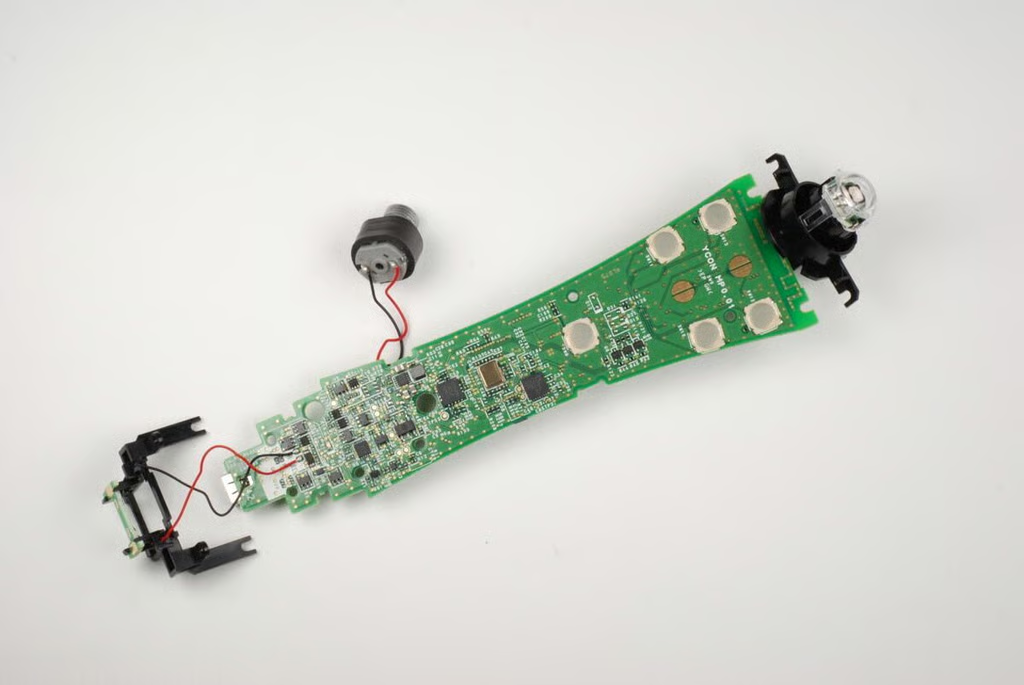
Photo by: Bill Detwiler / TechRepublic
Caption by: Bill Detwiler
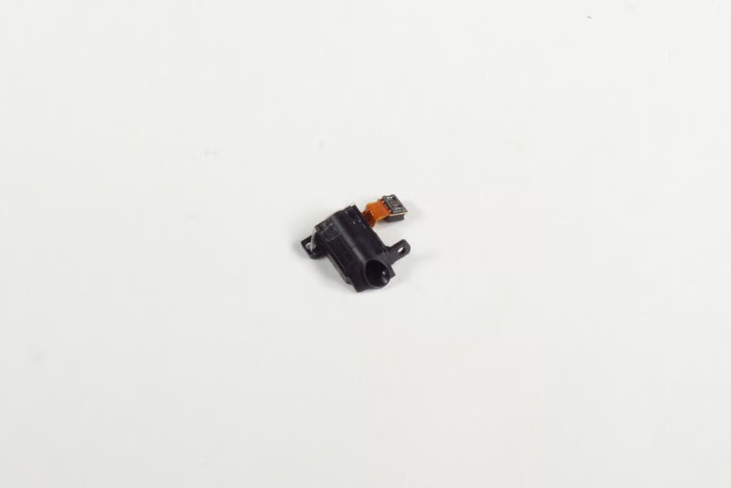
Photo by: Bill Detwiler / TechRepublic
Caption by: Bill Detwiler
The volume button contacts are covered with a think metal shield. I removed it to ensure that it wouldn’t block the logic board’s removal.
Photo by: Bill Detwiler / TechRepublic
Caption by: Bill Detwiler
As the front panel is still connected to the logic board with two extremely thin ribbon cables, I’ll need to be extra careful when I start prying out the logic board.
Photo by: Bill Detwiler / TechRepublic
Caption by: Bill Detwiler
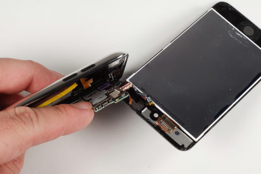
Photo by: Bill Detwiler / TechRepublic
Caption by: Bill Detwiler
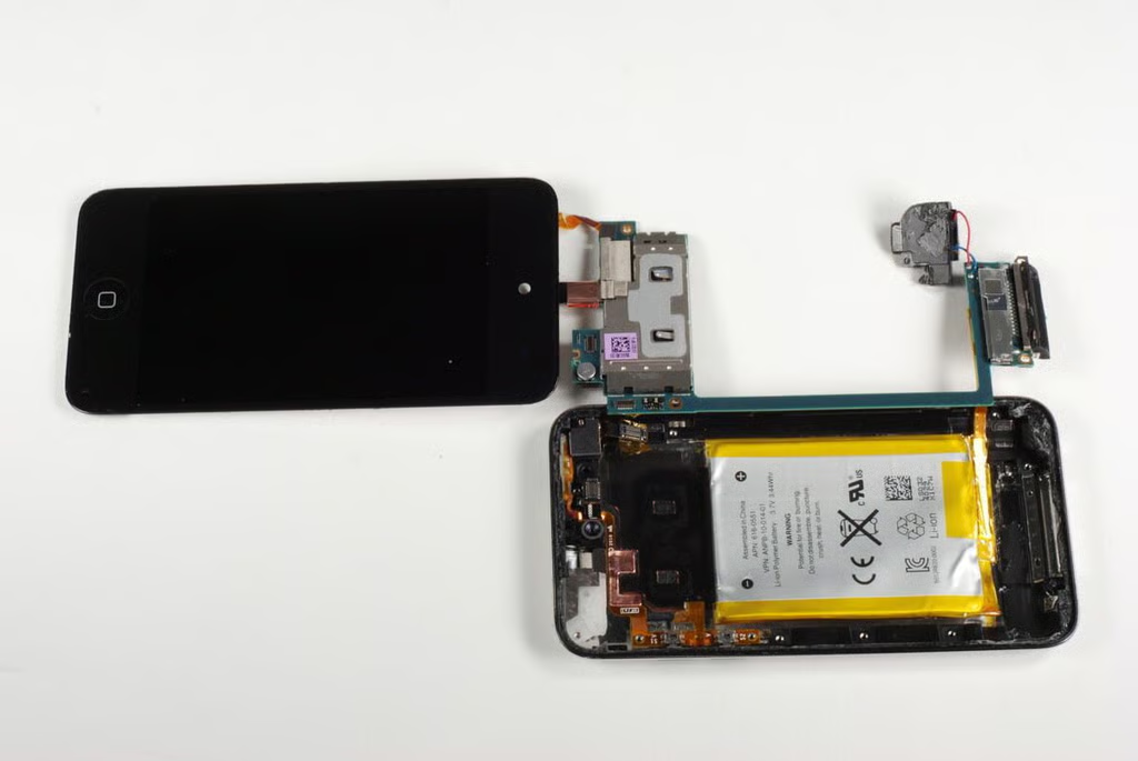
Starting at the top of the iPod Touch, I gently lifted up on the logic board until I would rotate it away from the case. Much to my annoyance, there seemed to be more adhesive hold the logic board in place. Apple clearly DID NOT design the 4th generation iPod Touch to be user-serviceable.
Photo by: Bill Detwiler / TechRepublic
Caption by: Bill Detwiler
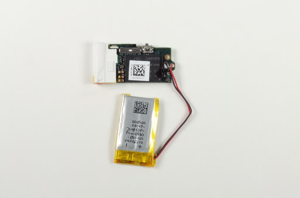
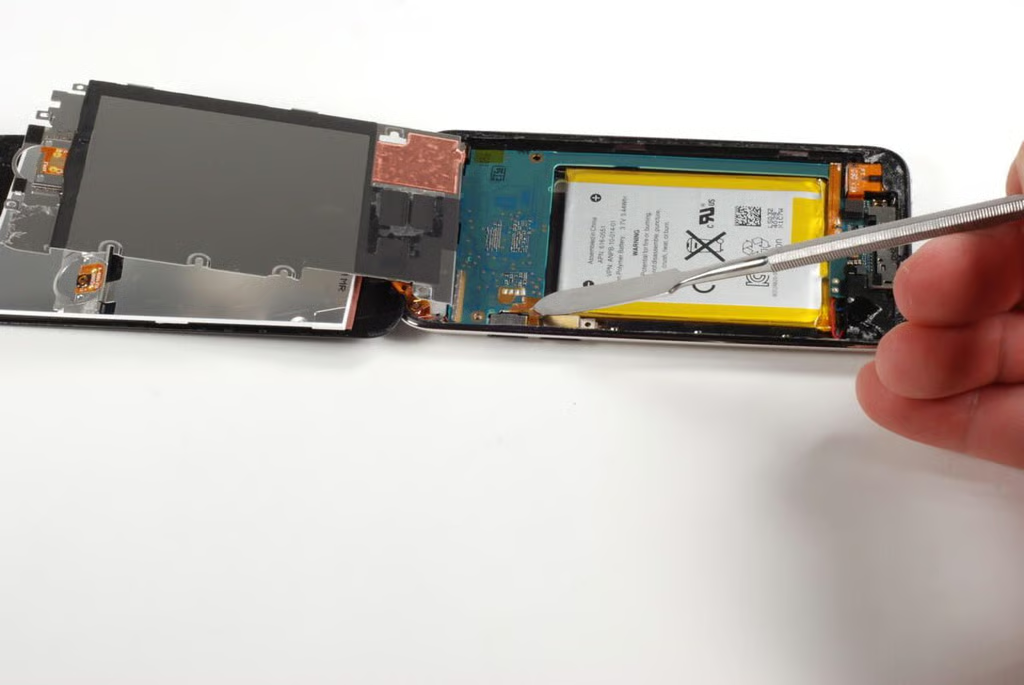
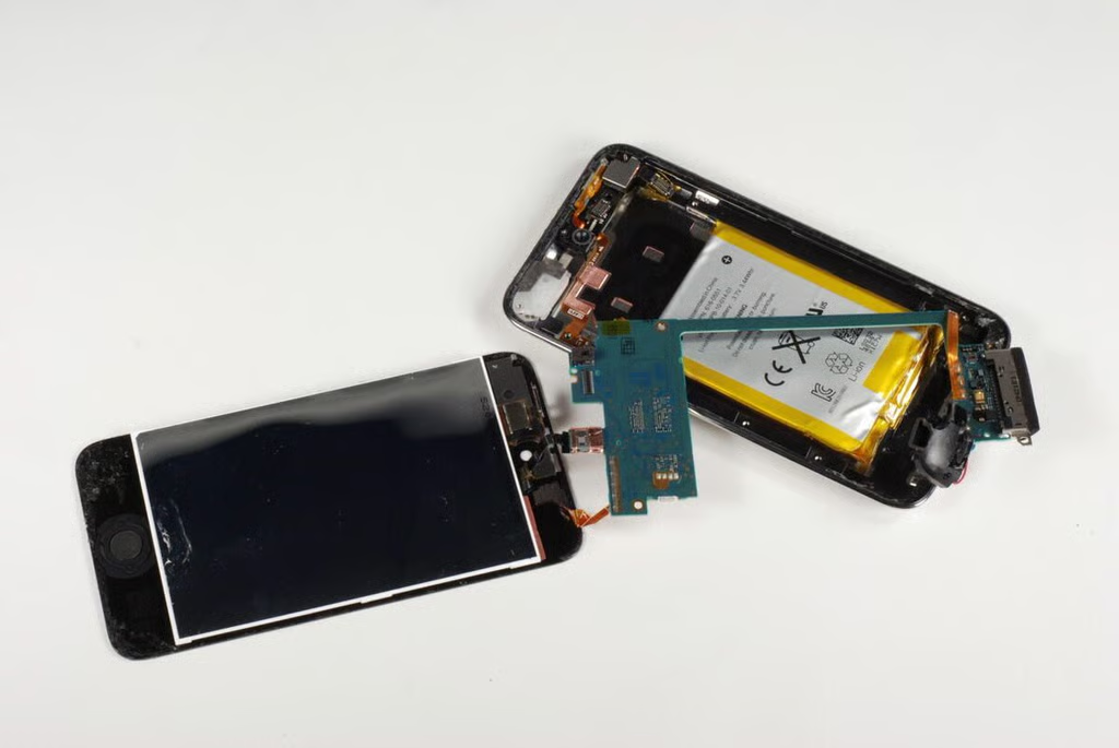
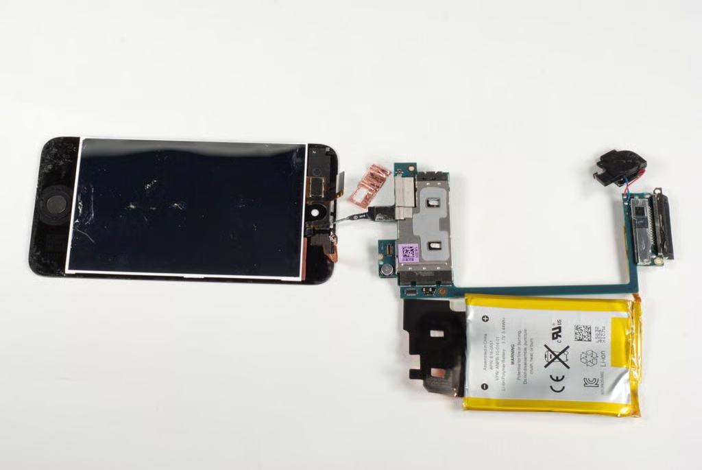
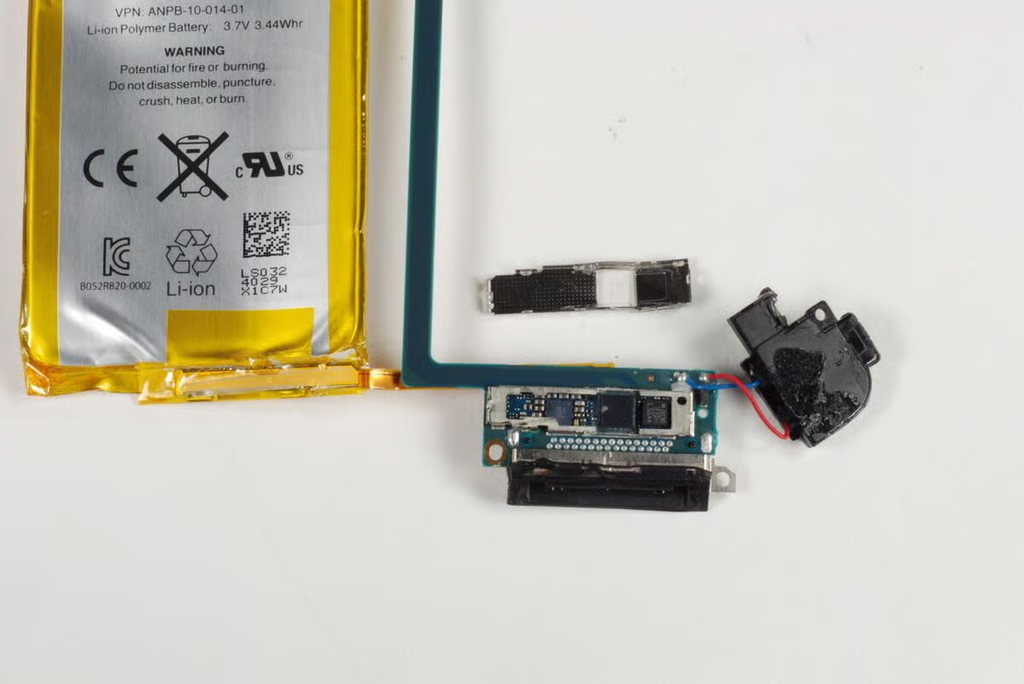
As the battery is soldered to the logic board, we’ll need to remove it from the case before the board can be totally free. Unfortunately, the battery is stuck to the case with some pretty strong adhesive. You’ll need to pry it loose.
Photo by: Bill Detwiler / TechRepublic
Caption by: Bill Detwiler
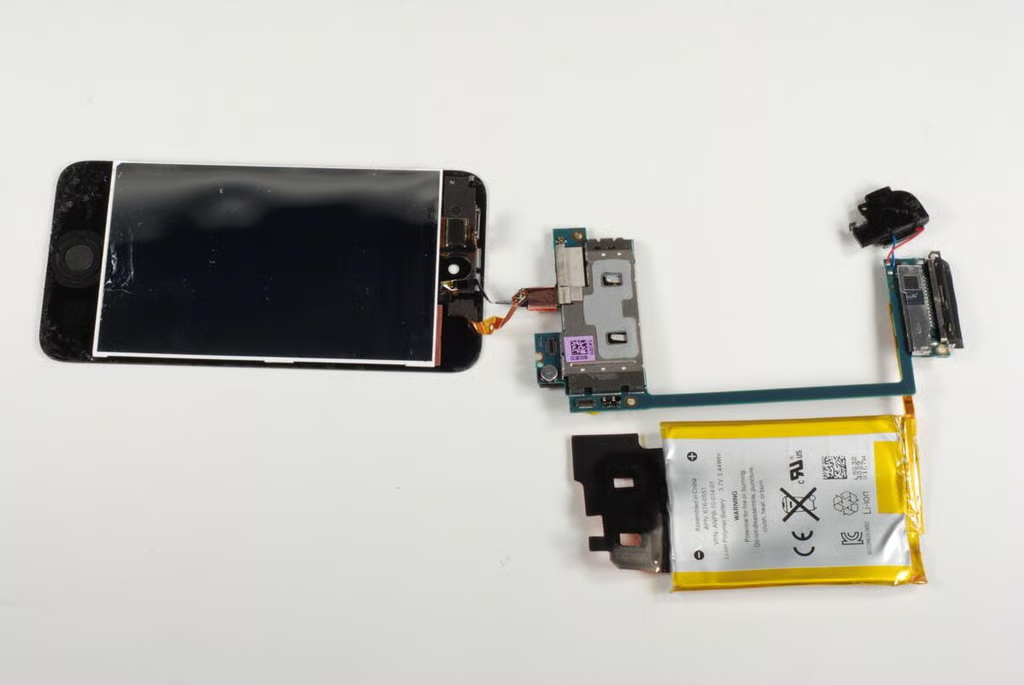
Photo by: Bill Detwiler / TechRepublic
Caption by: Bill Detwiler
With most of the internal components removed, only the two cameras and button assemblies remain in the iPod Touch’s metal case. We’ll remove those components in a bit. But for now, let’s look at the logic board and attached hardware.
Photo by: Bill Detwiler / TechRepublic
Caption by: Bill Detwiler
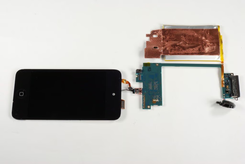
There are two connectors remaining between the front panel and logic board. The connector on the thin copper-color ribbon cable should pop loose. Unfortunately, the thin black cable in the center is a bit more challenging.
Photo by: Bill Detwiler / TechRepublic
Caption by: Bill Detwiler
A thin strip of copper film covers the black cable’s connector. With a little patience, you should be able to remove the film without damaging the connector or the cable.
Photo by: Bill Detwiler / TechRepublic
Caption by: Bill Detwiler
With the copper film removed, you can disconnect the last ribbon cable from the logic board.
Photo by: Bill Detwiler / TechRepublic
Caption by: Bill Detwiler
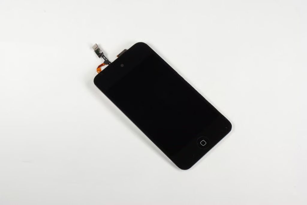
The iPod Touch’s retina display is fused to the front panel. Replacing a damaged screen will involved replacing the entire part.
Photo by: Bill Detwiler / TechRepublic
Caption by: Bill Detwiler
Photo by: Bill Detwiler / TechRepublic
Caption by: Bill Detwiler
Before we look at the chips on the logic board, let’s remove the iPod Touch’s cameras and buttons from the metal case.
Photo by: Bill Detwiler / TechRepublic
Caption by: Bill Detwiler
There is a small, white plastic spacer that is mounted next to the front-facing camera. I removed it before disconnecting the cameras.
Photo by: Bill Detwiler / TechRepublic
Caption by: Bill Detwiler
The iPod Touch’s rear-facing camera is hidden behind a small metal shield. You’ll need to remove the shield, he disconnect the camera’s connector before lift the camera away from the metal case.
Photo by: Bill Detwiler / TechRepublic
Caption by: Bill Detwiler
Photo by: Bill Detwiler / TechRepublic
Caption by: Bill Detwiler
Photo by: Bill Detwiler / TechRepublic
Caption by: Bill Detwiler
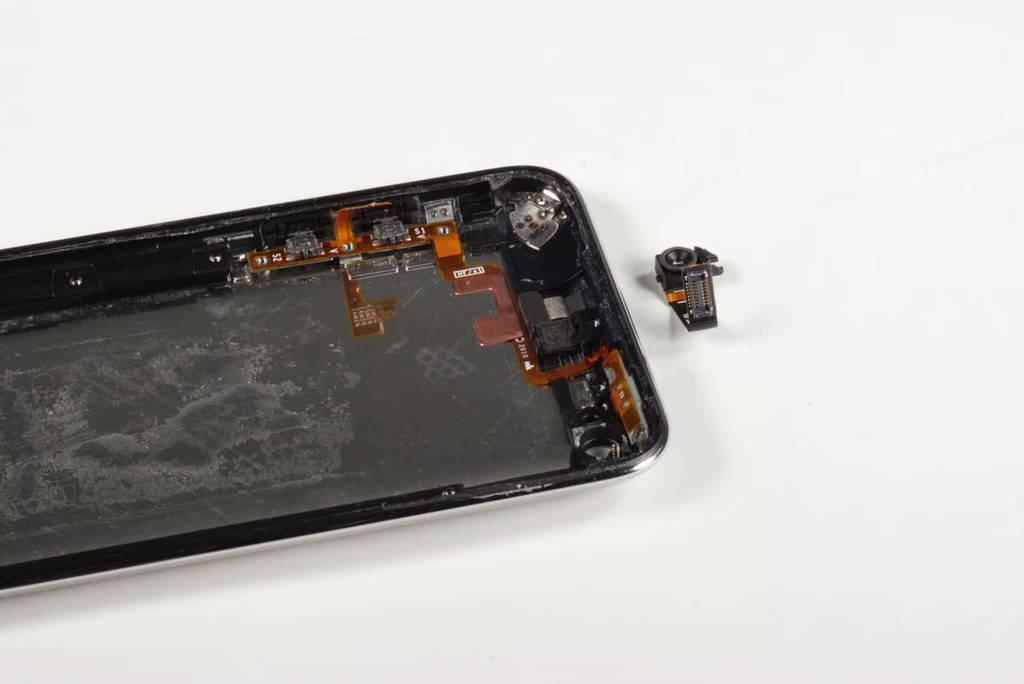
The iPod Touch’s front-facing camera is easily removed by disconnecting its cable from the logic board.
Photo by: Bill Detwiler / TechRepublic
Caption by: Bill Detwiler
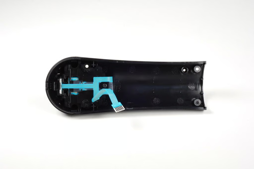
Photo by: Bill Detwiler / TechRepublic
Caption by: Bill Detwiler
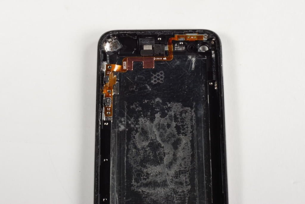
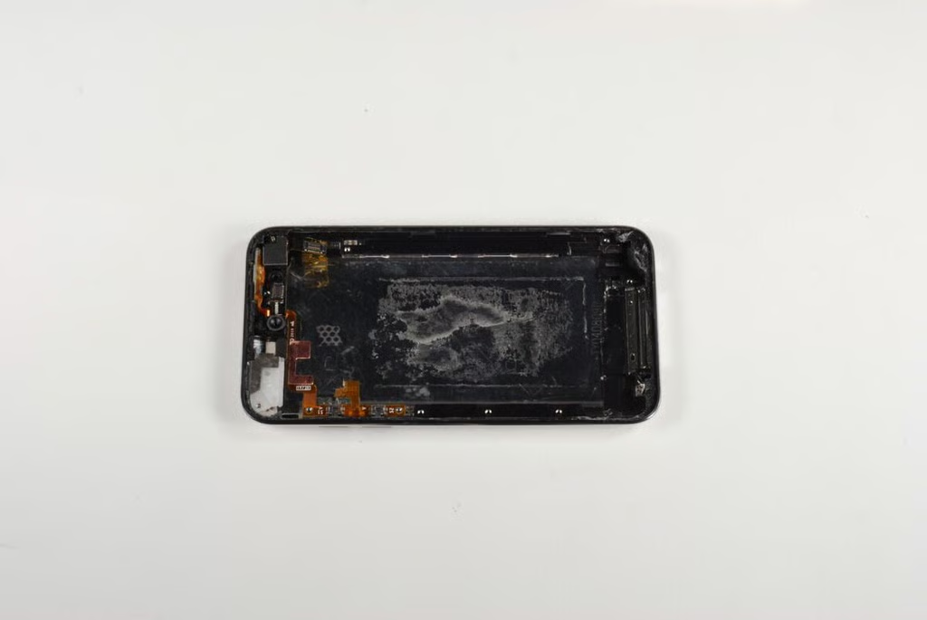
About the only thing left inside the iPod Touch’s metal case are the cable for the Sleep/wake and volume buttons and the buttons themselves. This very thin ribbon cable is glued to the case and should have been removed with the logic board–as its connector is soldered to the board. Unfortunately, I accidentally tore the cable when trying to remove the iPod Touch’s large metal EMI shield.
Photo by: Bill Detwiler / TechRepublic
Caption by: Bill Detwiler
Photo by: Bill Detwiler / TechRepublic
Caption by: Bill Detwiler
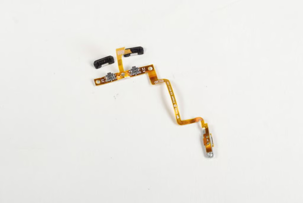
Photo by: Bill Detwiler / TechRepublic
Caption by: Bill Detwiler
Most of the main chips on the logic board are covered with a metal EMI shield. We’ll need to pry the shield off to see the chips.
Photo by: Bill Detwiler / TechRepublic
Caption by: Bill Detwiler
Luckily the logic board’s EMI shield is too difficult to remove.
Photo by: Bill Detwiler / TechRepublic
Caption by: Bill Detwiler
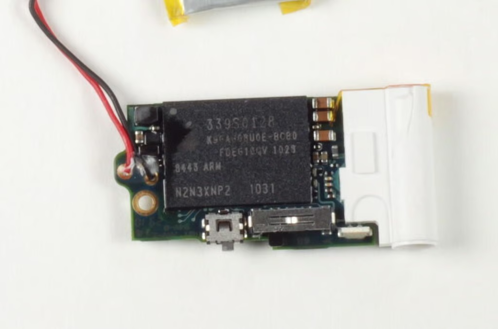
With the shield removed, we can see three large chips.
Photo by: Bill Detwiler / TechRepublic
Caption by: Bill Detwiler
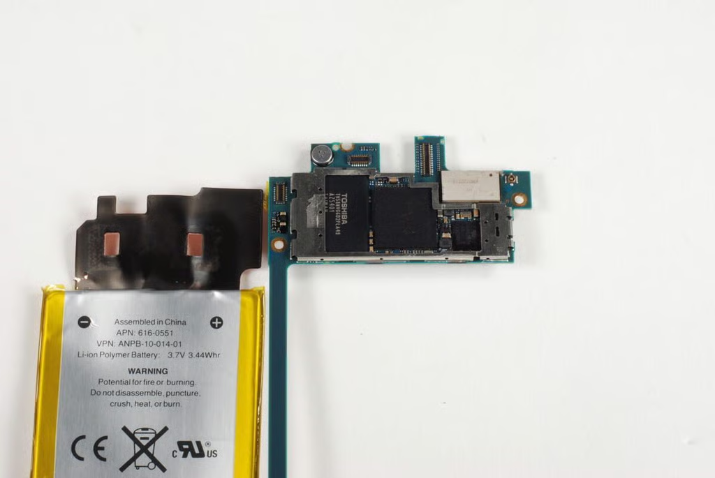
The large chip in the center is the Apple A4 processor, which is also used in the iPhone 4 and iPad. To the left is the large Toshiba NAND flash memory module (TH58NVG6D2FLA49). The metal plate in the top right corner of the logic board likely covers the wireless chips.
Photo by: Bill Detwiler / TechRepublic
Caption by: Bill Detwiler
Another small metal EMI shield covers three chips on the lower half of the logic board.
Photo by: Bill Detwiler / TechRepublic
Caption by: Bill Detwiler
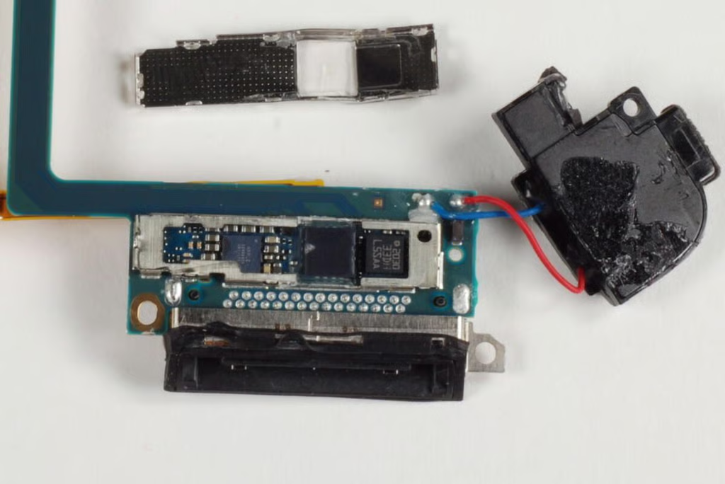
The chip on the far left is likely the audio codec, and the chip in the center is likely the gyroscope.
Photo by: Bill Detwiler / TechRepublic
Caption by: Bill Detwiler
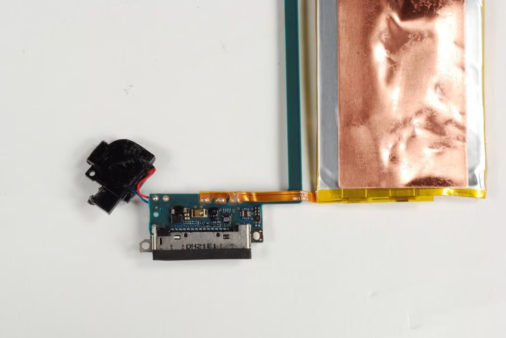
Not much to see on the back of the the logic board’s lower half, except the solder points for the speaker and battery.
Photo by: Bill Detwiler / TechRepublic
Caption by: Bill Detwiler
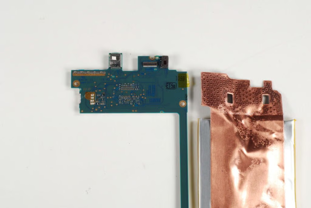
Photo by: Bill Detwiler / TechRepublic
Caption by: Bill Detwiler
Bill Detwiler is the Editor for Technical Content and Ecosystem at Celonis. He is the former Editor in Chief of TechRepublic and previous host of TechRepublic's Dynamic Developer podcast and Cracking Open, CNET and TechRepublic's popular online show. Previously, Bill was an IT manager in the social research and energy industries. He has bachelor's and master's degrees from the University of Louisville, where he has also lectured on computer crime and crime prevention.


