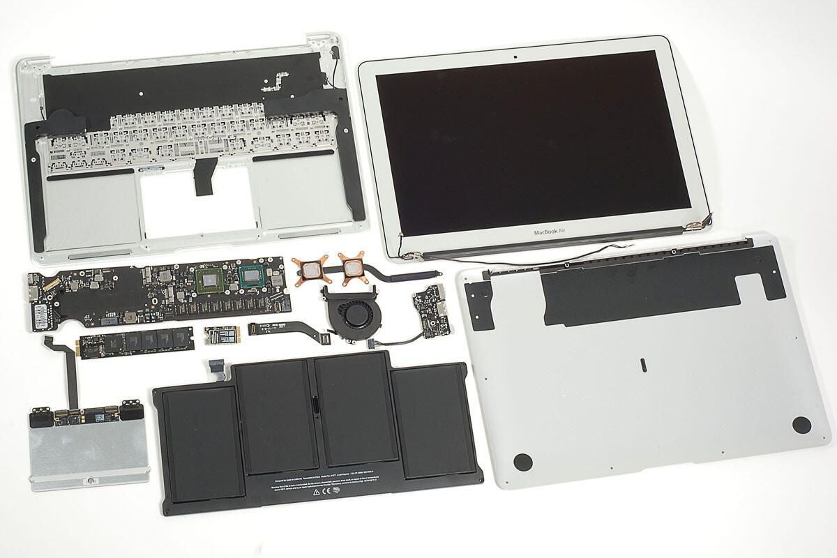
In October 2010, Apple released the 2nd generation MacBook Air. The redesigned notebook is available in 11-inch and 13-inch models. We cracked open the 1st generation MacBook Air (released in 2008) and couldn’t wait to get our hands on the 2010 model.
Follow along as we crack open the 13-inch MacBook Air.
To disassemble the new Air you’ll need a screwdriver with Torx T5 and T9 bits and either a very small flathead screwdriver or a special five-point Torx security bit.
Don’t forget to check out our teardown of the 11-inch MacBook Air.
Photo by: Bill Detwiler / TechRepublic
Caption by: Bill Detwiler
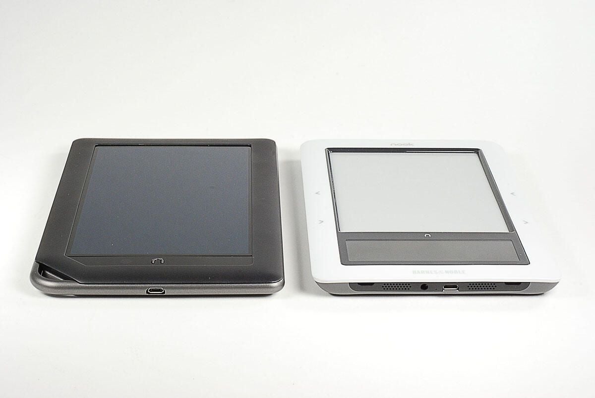
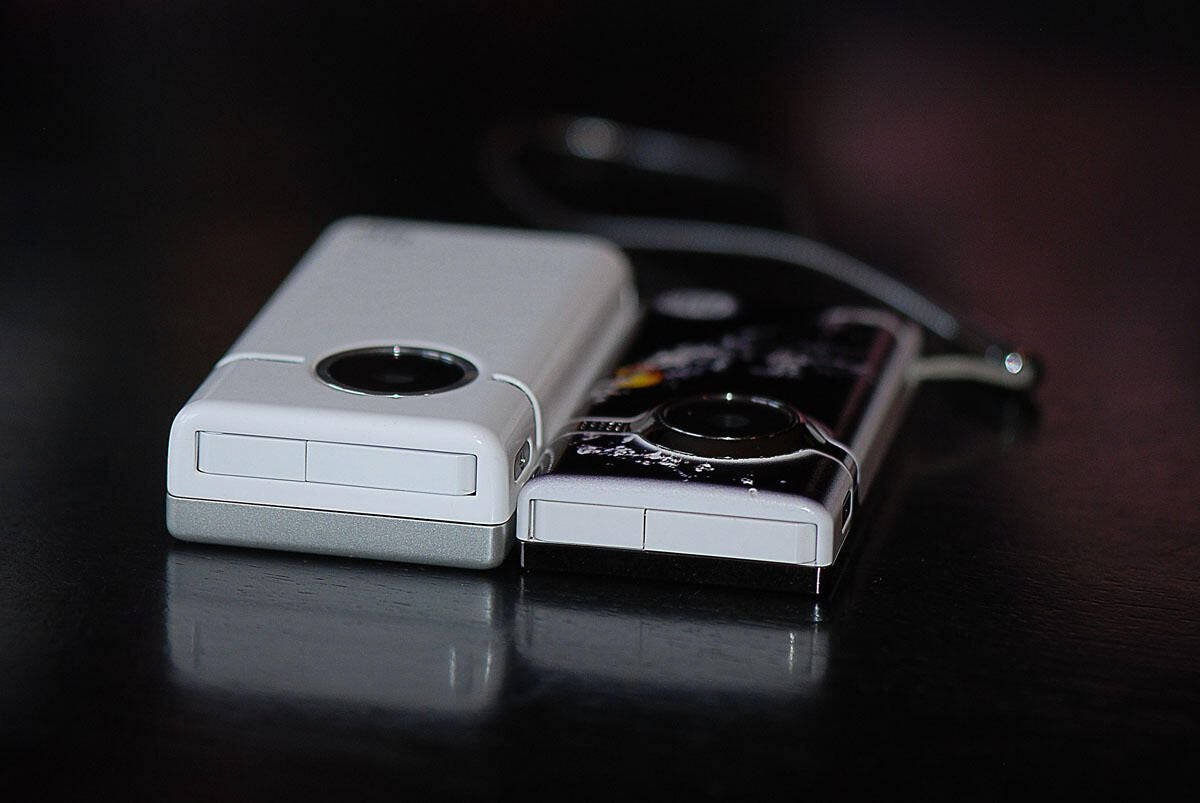
We purchased both an 11-inch and 13-inch MacBook Air. In this photo, the smaller Air is sitting on the larger.
Photo by: Bill Detwiler / TechRepublic
Caption by: Bill Detwiler
Photo by: Bill Detwiler / TechRepublic
Caption by: Bill Detwiler
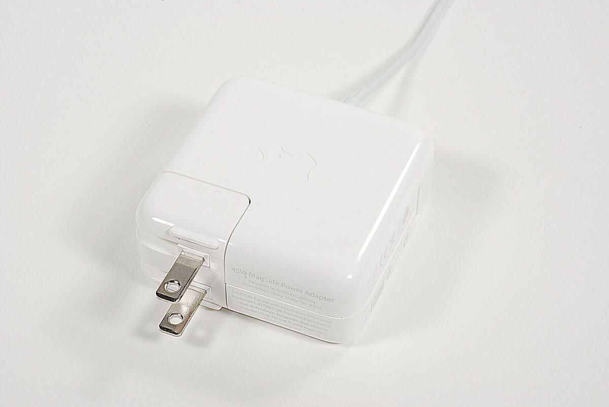
Both the 13-inch and 11-inch MacBook Airs use a 45W MagSafe Power Adapter.
Photo by: Bill Detwiler / TechRepublic
Caption by: Bill Detwiler
Photo by: Bill Detwiler / TechRepublic
Caption by: Bill Detwiler
Photo by: Bill Detwiler / TechRepublic
Caption by: Bill Detwiler
Although the MacBook Air’s case screws are easily accessible on the bottom panel, Apple used 5-point, tamper-resistant Torx screws.
Photo by: Bill Detwiler / TechRepublic
Caption by: Bill Detwiler
As with the 11-inch MacBook Air, I was able to remove all 10 case screws with a small slotted screwdriver.
Photo by: Bill Detwiler / TechRepublic
Caption by: Bill Detwiler
While I slightly damaged a few of the screw heads, I should be able to put them back in. If you’re going to work on the new MacBook Air, I recommend getting a screwdriver specifically made for this type of screw.
Photo by: Bill Detwiler / TechRepublic
Caption by: Bill Detwiler
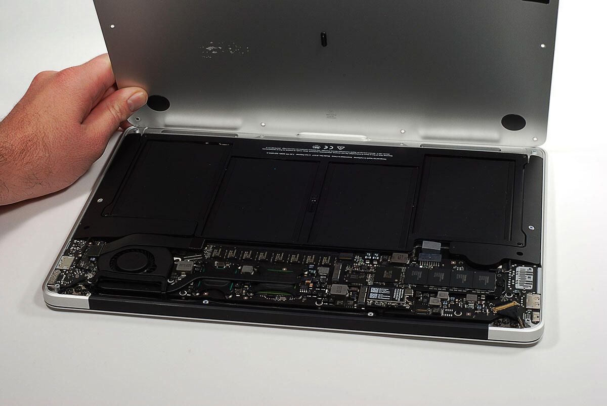
With the case screws removed, you can lift the bottom panel away from the case.
Photo by: Bill Detwiler / TechRepublic
Caption by: Bill Detwiler
Five Torx T5 screws hold the battery in place.
Photo by: Bill Detwiler / TechRepublic
Caption by: Bill Detwiler
Photo by: Bill Detwiler / TechRepublic
Caption by: Bill Detwiler
Photo by: Bill Detwiler / TechRepublic
Caption by: Bill Detwiler
The 2010, 13-inch MacBook Air has a 7.3V, 50Wh Li-ion battery. The 11-inch Air has a a 7.3V, 35Wh Li-ion battery.
Photo by: Bill Detwiler / TechRepublic
Caption by: Bill Detwiler
Next, I’ll remove the cooling fan, which is held in place by four Torx T5 screws–one of which is hidden under the cables that run along the bottom of the fan’s housing.
Photo by: Bill Detwiler / TechRepublic
Caption by: Bill Detwiler
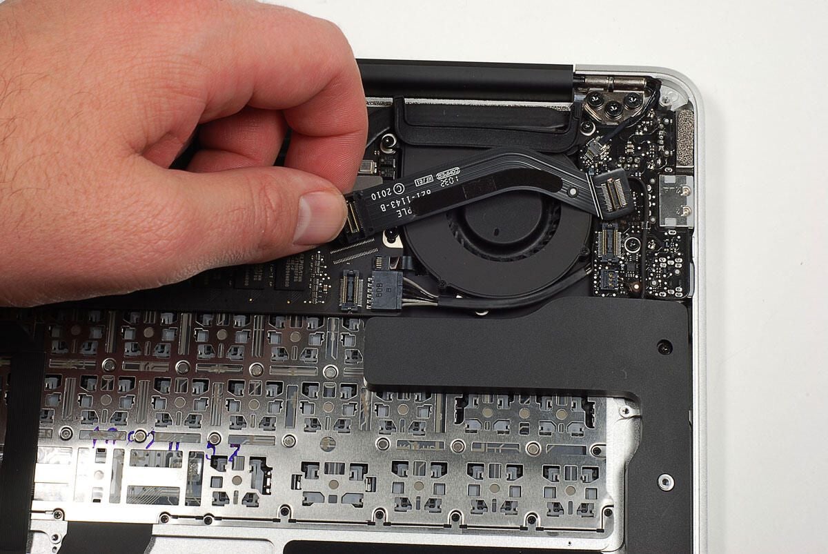
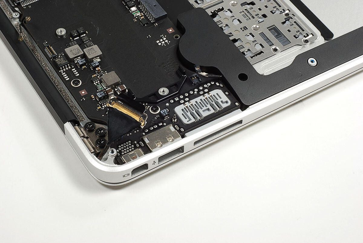
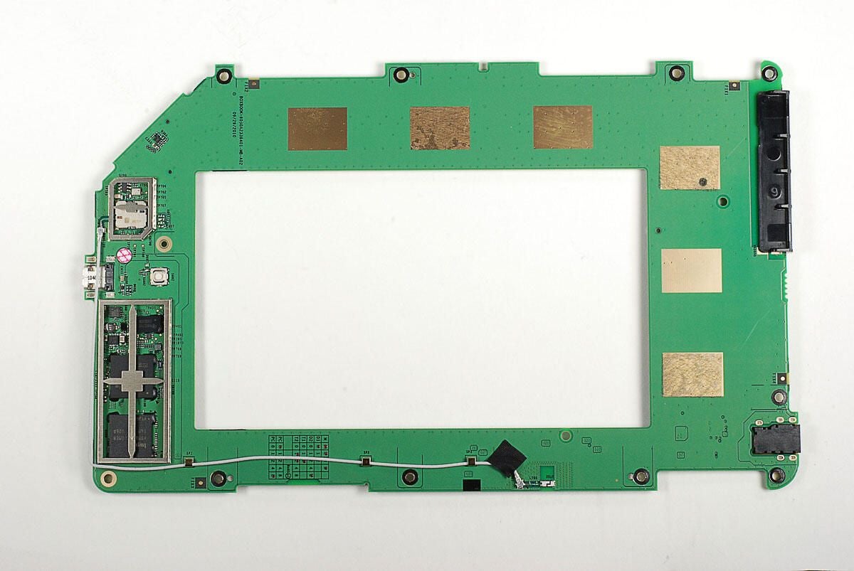
Before removing the fan, you’ll need to detach both ends of a thin ribbon cable that connects the small, left-side circuit board to the main logic board. This smaller board contains the MagSafe power port, one of the unit’s two USB ports, and the headphone jack.
Photo by: Bill Detwiler / TechRepublic
Caption by: Bill Detwiler
With all the screws removed, and the cables disconnected, you can lift the cooling fan away from the main logic board.
Photo by: Bill Detwiler / TechRepublic
Caption by: Bill Detwiler
As I noted earlier, one of the fan screws is hidden under a cable that runs along the bottom of the fan’s housing. There’s also a single Torx T5 screw that holds the left-side circuit board to the case.
Photo by: Bill Detwiler / TechRepublic
Caption by: Bill Detwiler
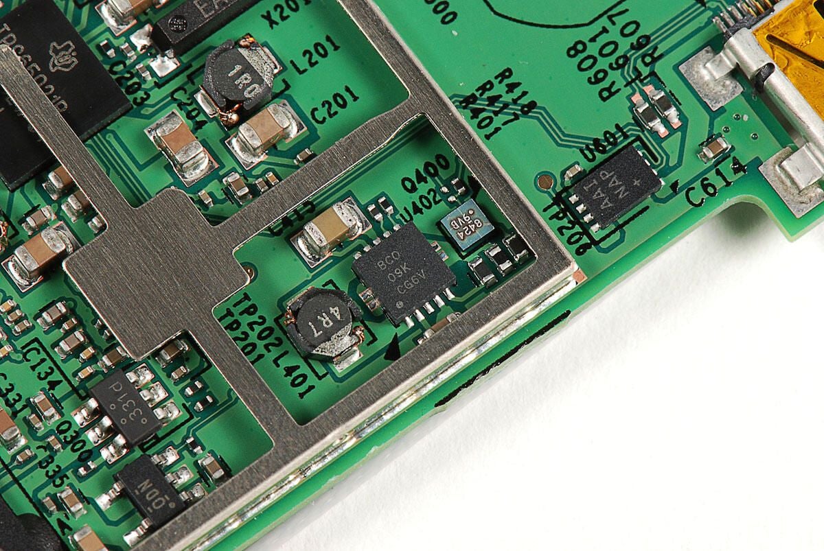
The small circuit board, located on the case’s left side, contains the MagSafe power port, USB port, and headphone jack.
Photo by: Bill Detwiler / TechRepublic
Caption by: Bill Detwiler
Photo by: Bill Detwiler / TechRepublic
Caption by: Bill Detwiler

Photo by: Bill Detwiler / TechRepublic
Caption by: Bill Detwiler
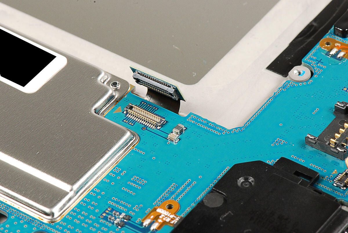
Photo by: Bill Detwiler / TechRepublic
Caption by: Bill Detwiler
Photo by: Bill Detwiler / TechRepublic
Caption by: Bill Detwiler
The 2010 MacBook Air uses flash storage, exclusively. Our test unit came with 128GB. A single Torx T5 screw holds the unit in place. Once the screws is removed, you can disconnect the unit from the main logic board.
Photo by: Bill Detwiler / TechRepublic
Caption by: Bill Detwiler
A logic board screws is hidden under the SSD unit.
Photo by: Bill Detwiler / TechRepublic
Caption by: Bill Detwiler
The MacBook Air’s flash storage unit contains four main components–the circuit board, a Toshiba Solid State Drive controller, a Micron DDR DRAM cache, and the actual Toshiba flash memory chips.
Photo by: Bill Detwiler / TechRepublic
Caption by: Bill Detwiler
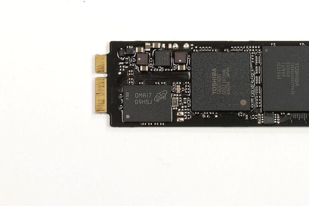
The 2010 MacBook Air’s storage unit has a MSI 0MA17 D9HSJ DRAM cache chip.
Photo by: Bill Detwiler / TechRepublic
Caption by: Bill Detwiler
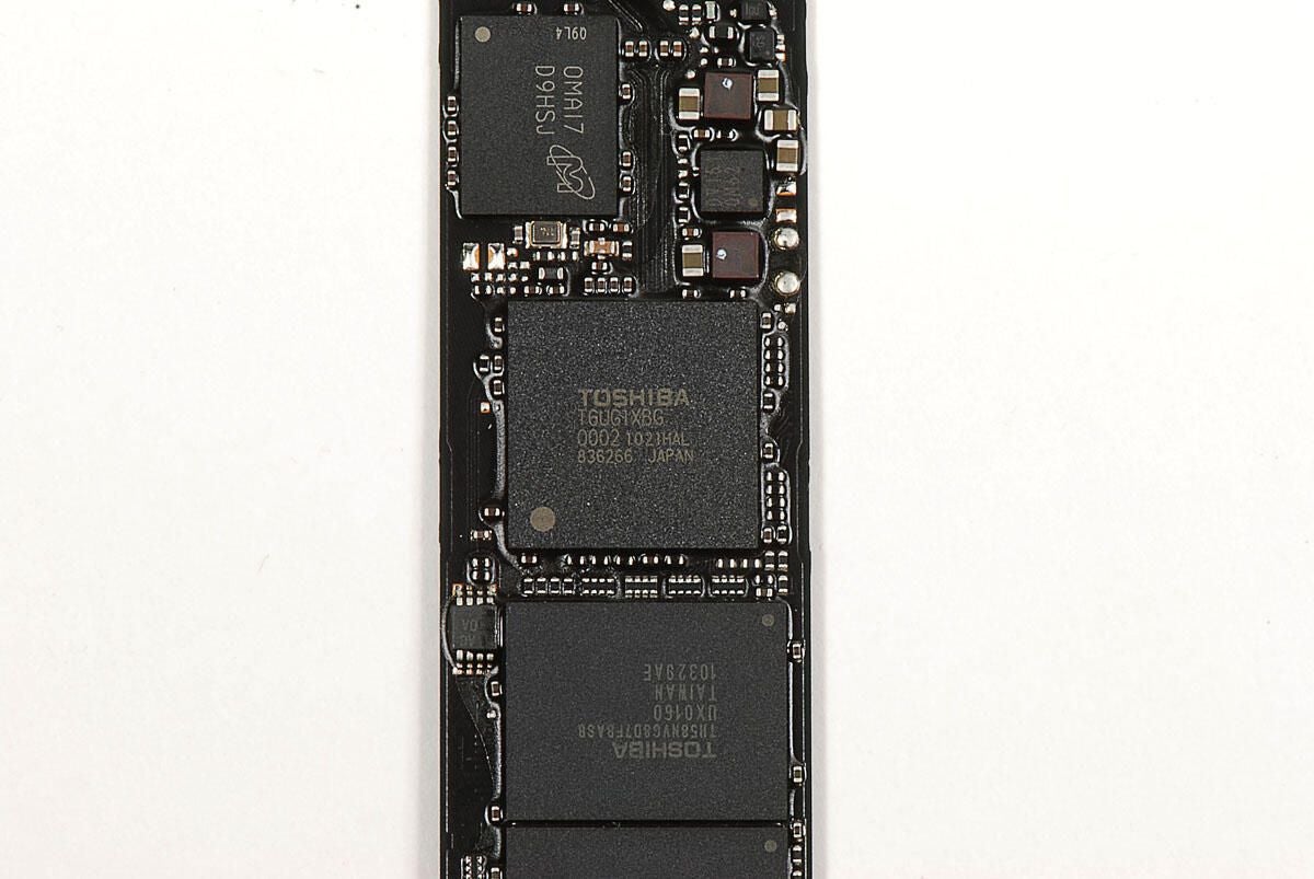
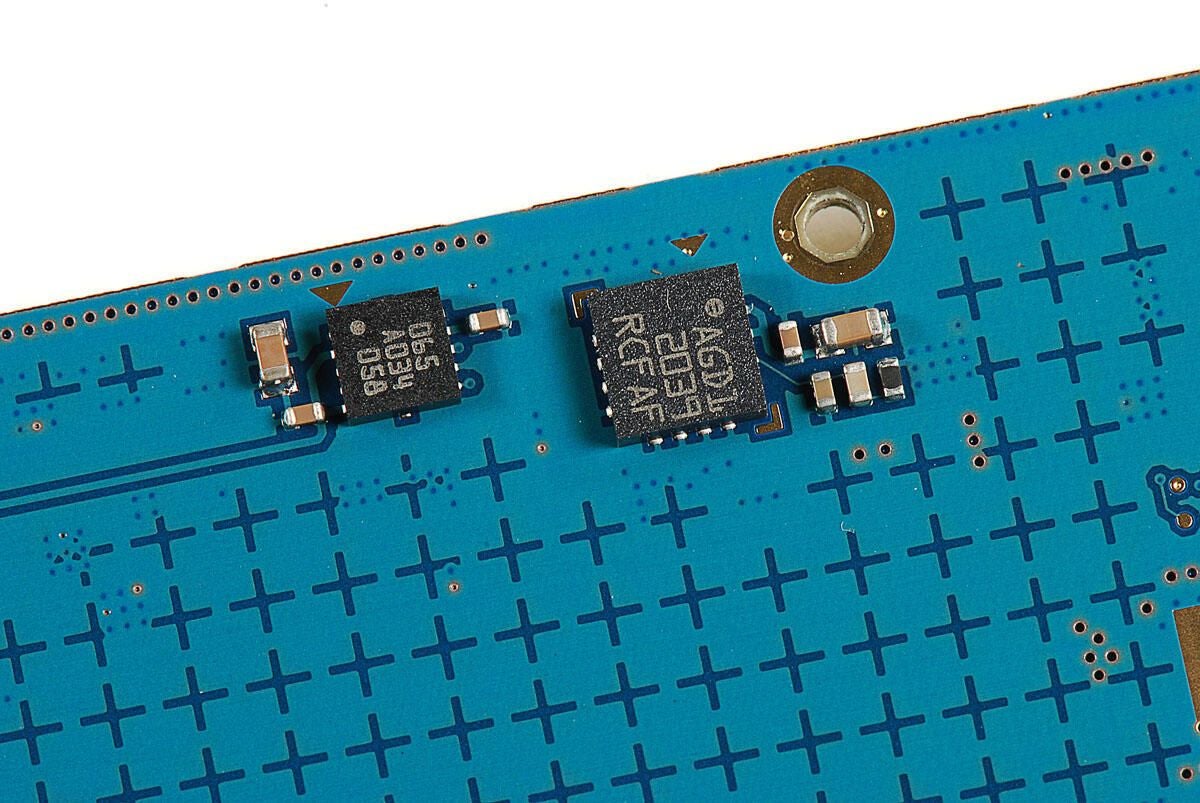
The 2010 MacBook Air uses a Toshiba T6UG1XBG Solid State Drive controller.
Photo by: Bill Detwiler / TechRepublic
Caption by: Bill Detwiler
Our 128GB MacBook Air’s flash memory storage unit has four Toshiba TH58NVG8D7FBASB 32GB flash chips.
Photo by: Bill Detwiler / TechRepublic
Caption by: Bill Detwiler
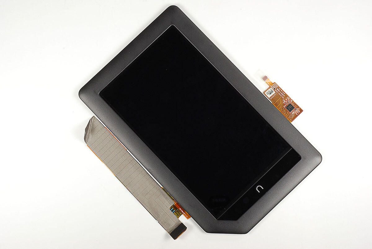
Photo by: Bill Detwiler / TechRepublic
Caption by: Bill Detwiler
A single Torx T5 screw holds the Broadcom BCM943224PCIEBT2 wireless card in place. You’ll also need to disconnect the antenna cables before removing the card.
Photo by: Bill Detwiler / TechRepublic
Caption by: Bill Detwiler
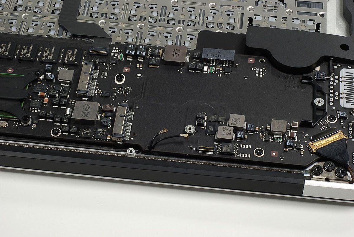
Photo by: Bill Detwiler / TechRepublic
Caption by: Bill Detwiler
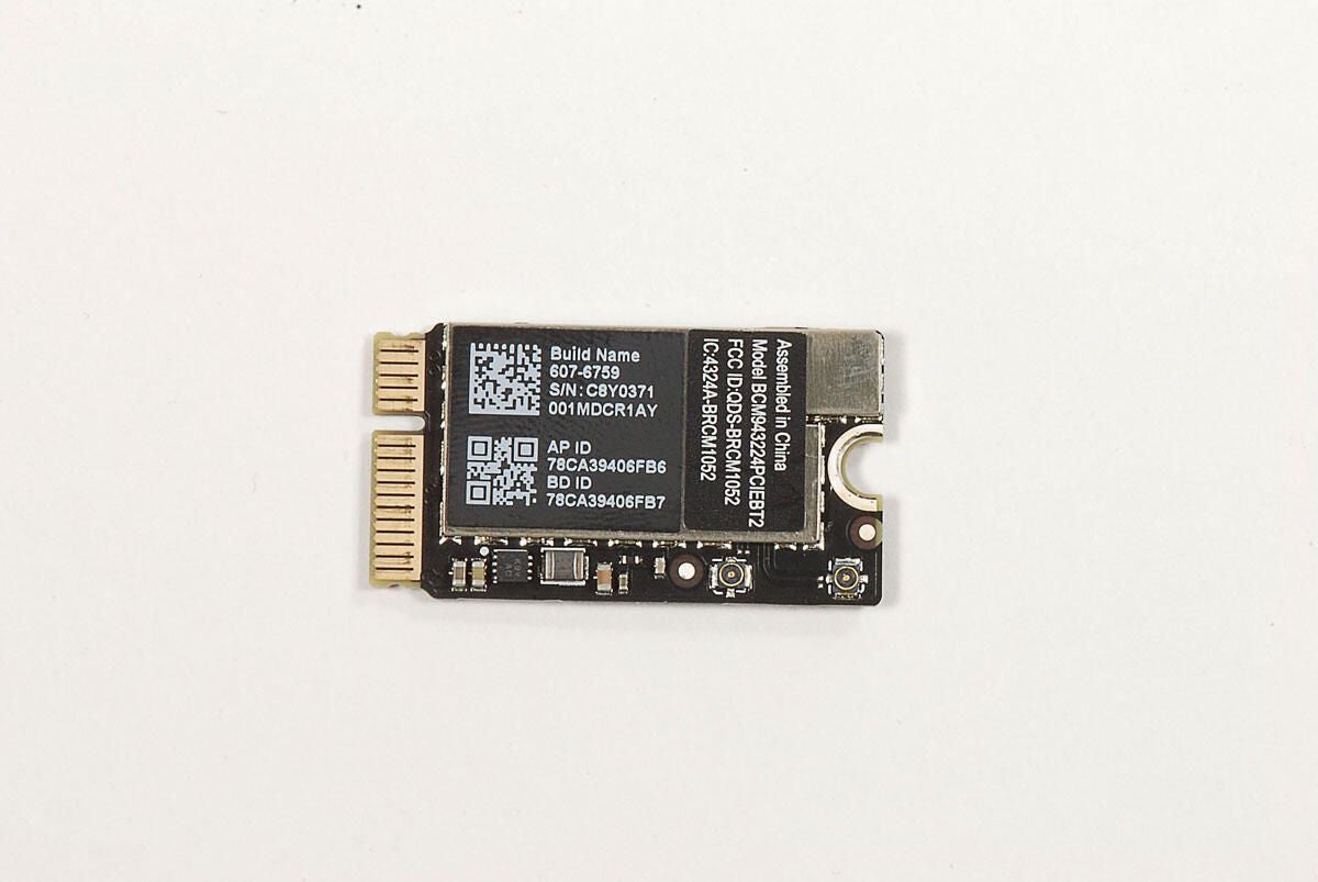
Photo by: Bill Detwiler / TechRepublic
Caption by: Bill Detwiler
Photo by: Bill Detwiler / TechRepublic
Caption by: Bill Detwiler
The display cable requires a fair amount of force to pull free of its connector, but luckily it has a small handle to pull on. With this cable separated from its connector, we can lift the logic board away from the case.
Photo by: Bill Detwiler / TechRepublic
Caption by: Bill Detwiler
Sixe Torx T5 screws hold the main logic board to the case. Five are clearly visible. You’ll also need to disconnect all the remaining cables before removing the logic board from the case.
Photo by: Bill Detwiler / TechRepublic
Caption by: Bill Detwiler
The sixth logic board screws is hidden under the wireless antenna cables. With the screws removed, you can lift the logic board away from the case.
Photo by: Bill Detwiler / TechRepublic
Caption by: Bill Detwiler
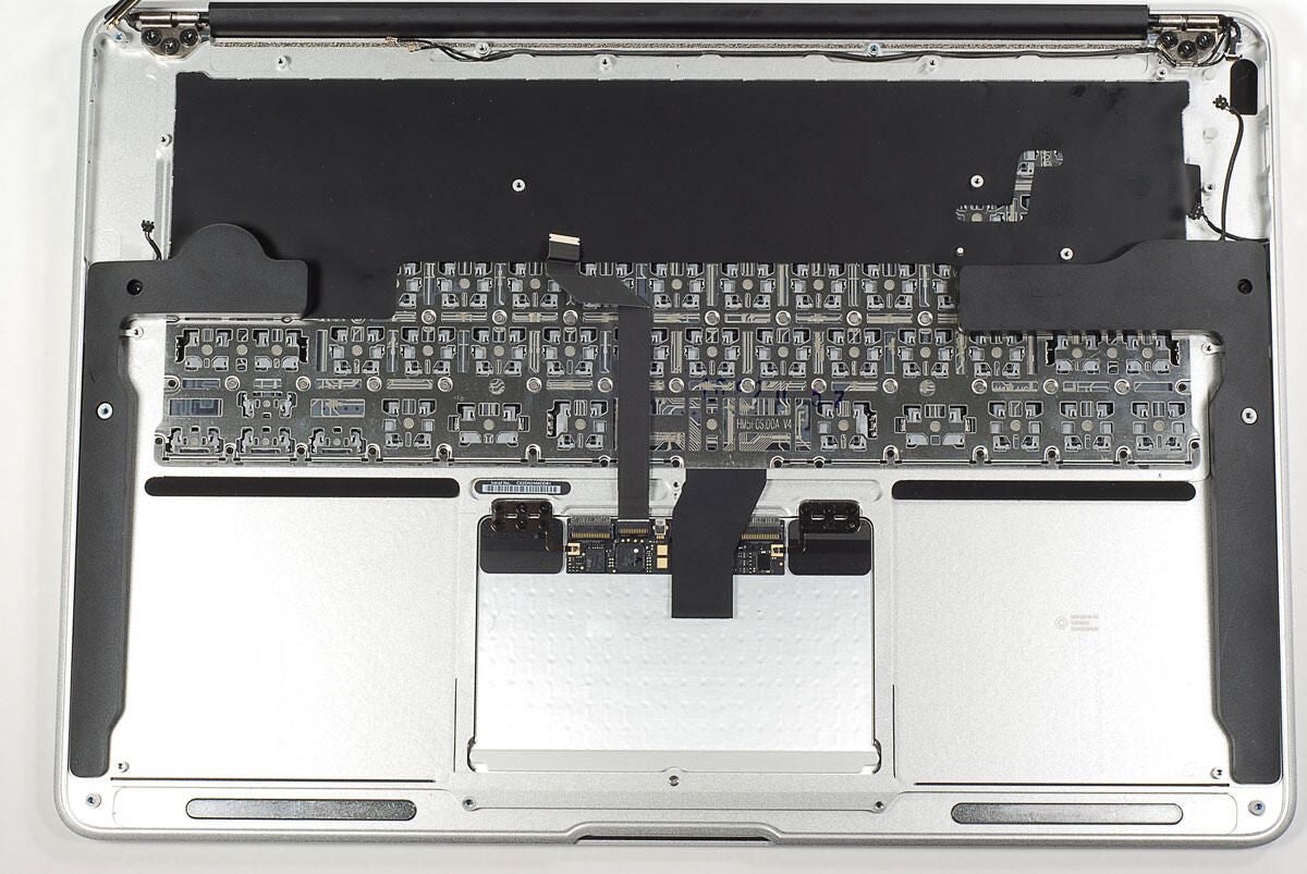
Photo by: Bill Detwiler / TechRepublic
Caption by: Bill Detwiler
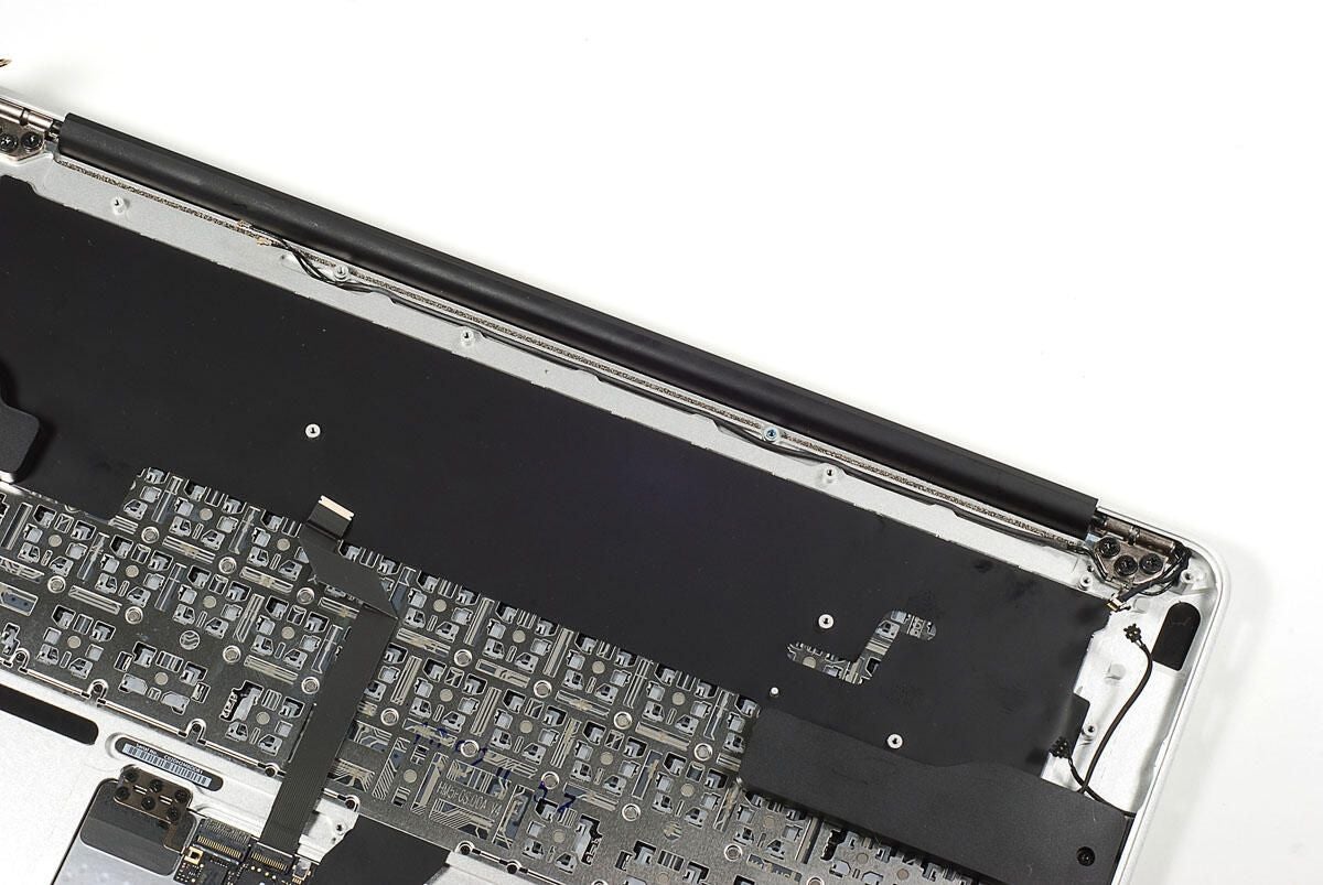
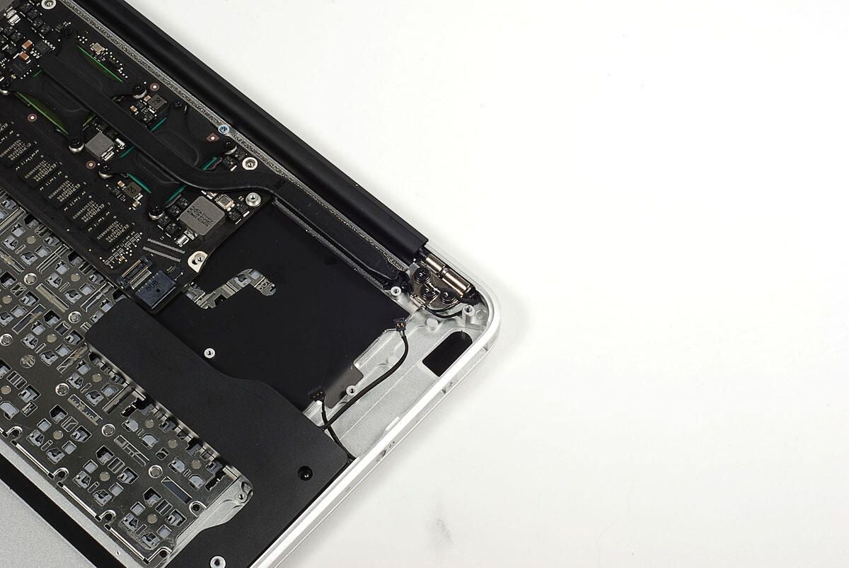
The wireless antenna cable runs along the case. You’ll need to pull this cable free from the case, before removing the display and lid.
Photo by: Bill Detwiler / TechRepublic
Caption by: Bill Detwiler
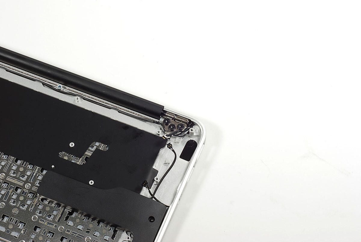
The MacBook Air’s display and lid are connected to the case via two hinges. Each hinge uses three Torx T9 screws–one more than the 11-inch Air.
Photo by: Bill Detwiler / TechRepublic
Caption by: Bill Detwiler
Photo by: Bill Detwiler / TechRepublic
Caption by: Bill Detwiler
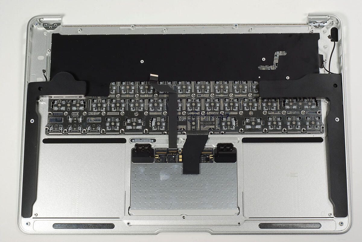
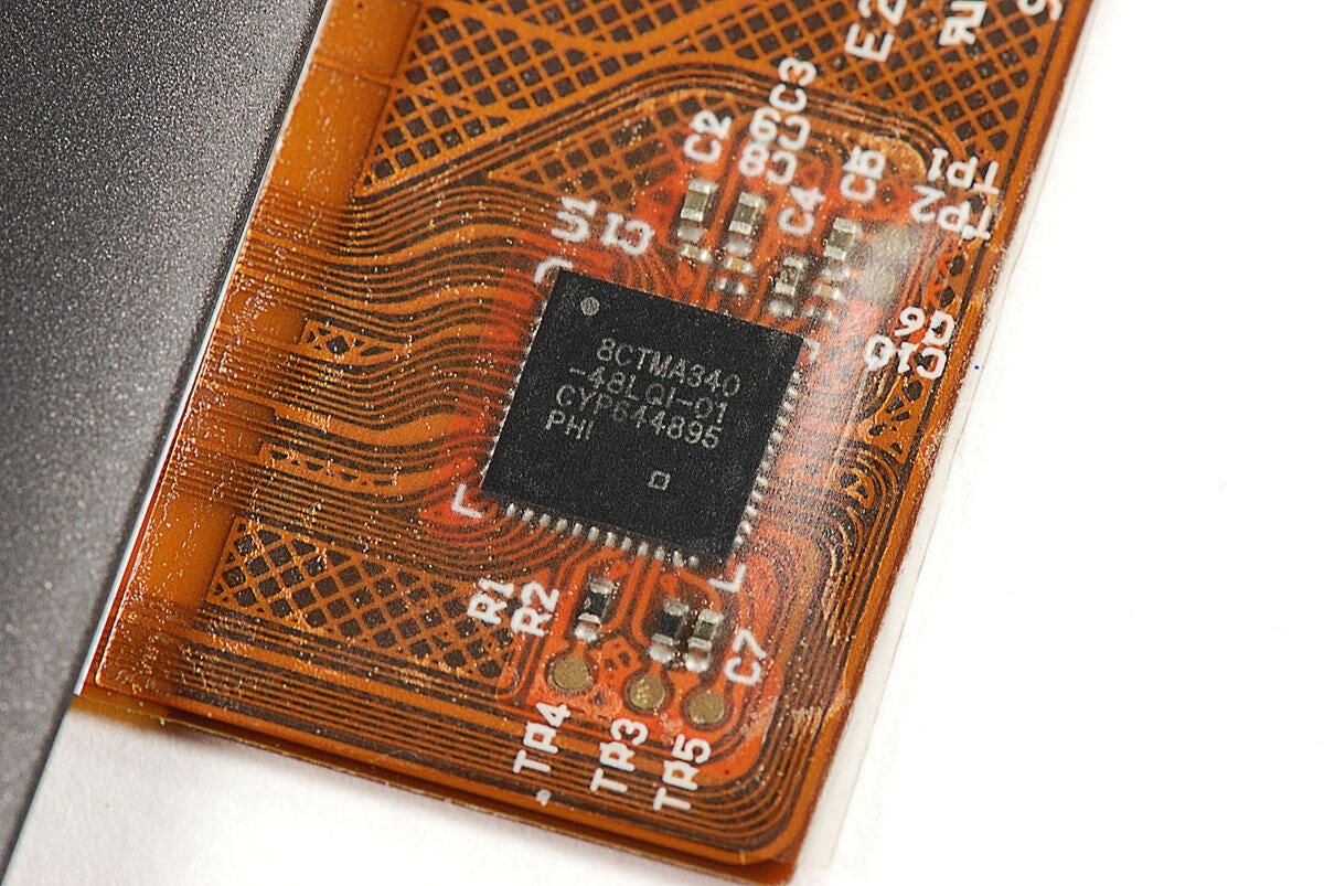
With the lid and display removed, we can turn our attention to the Multi-Touch Trackpad.
Photo by: Bill Detwiler / TechRepublic
Caption by: Bill Detwiler
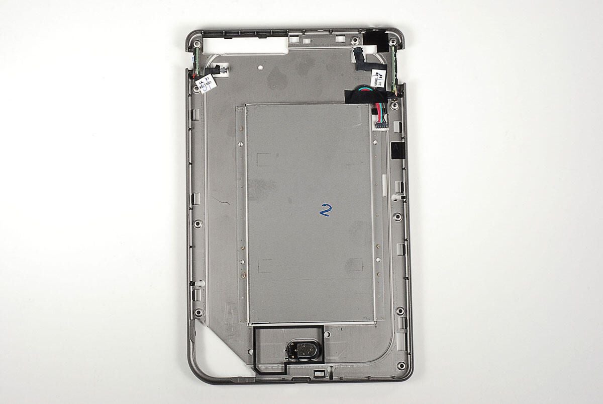
Although the twp brackets that hold the Multi-Touch TrackPad to the case use a total of 12 screws, you only to remove the six screws attached to the case to take out the Trackpad.
Photo by: Bill Detwiler / TechRepublic
Caption by: Bill Detwiler
Photo by: Bill Detwiler / TechRepublic
Caption by: Bill Detwiler
Photo by: Bill Detwiler / TechRepublic
Caption by: Bill Detwiler
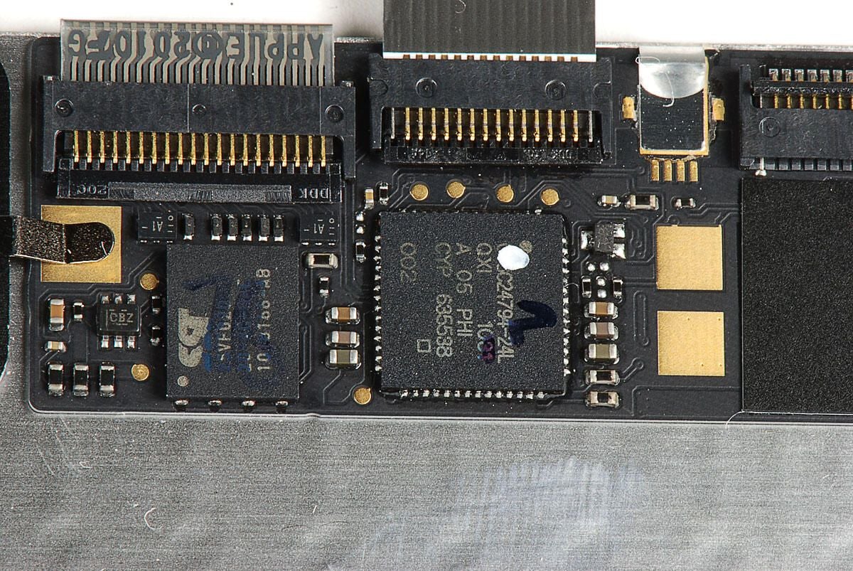
Photo by: Bill Detwiler / TechRepublic
Caption by: Bill Detwiler
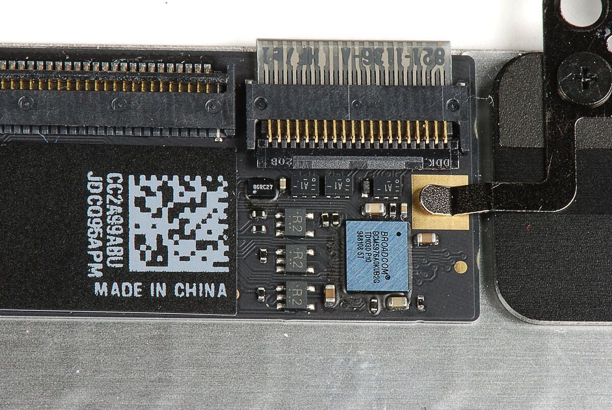
Photo by: Bill Detwiler / TechRepublic
Caption by: Bill Detwiler
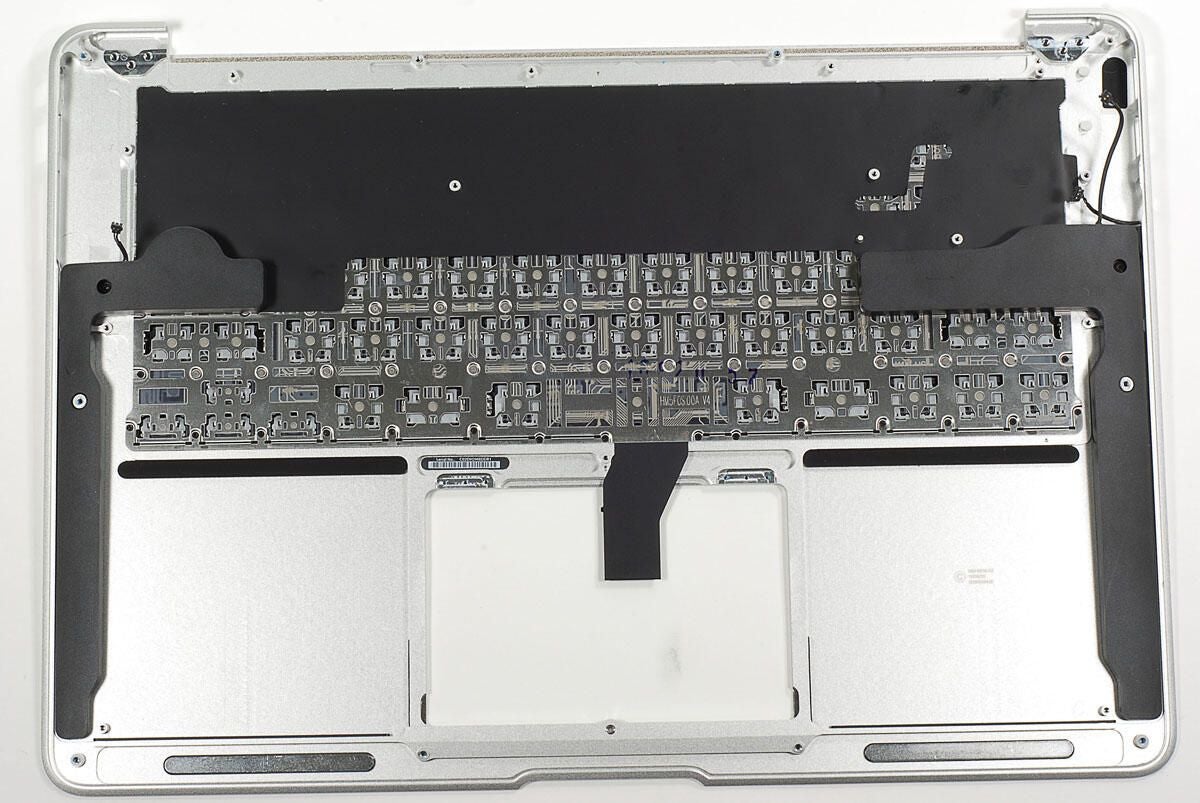
Photo by: Bill Detwiler / TechRepublic
Caption by: Bill Detwiler
The MacBook Air’s built-in microphone is located just above the speaker on the left side. As the speaker is glued to the case, I’m going to leave it in place.
Photo by: Bill Detwiler / TechRepublic
Caption by: Bill Detwiler
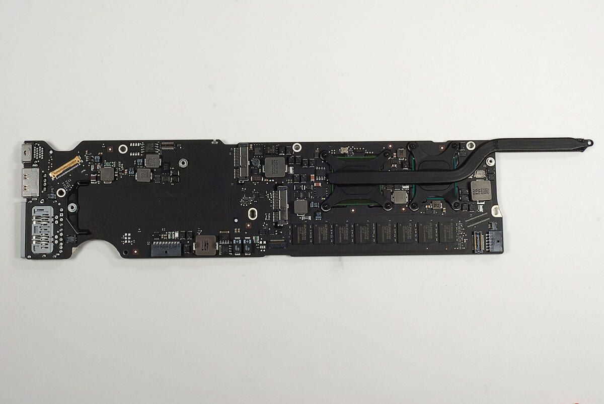
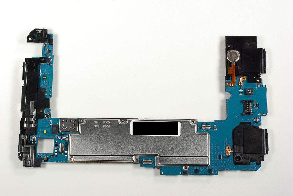
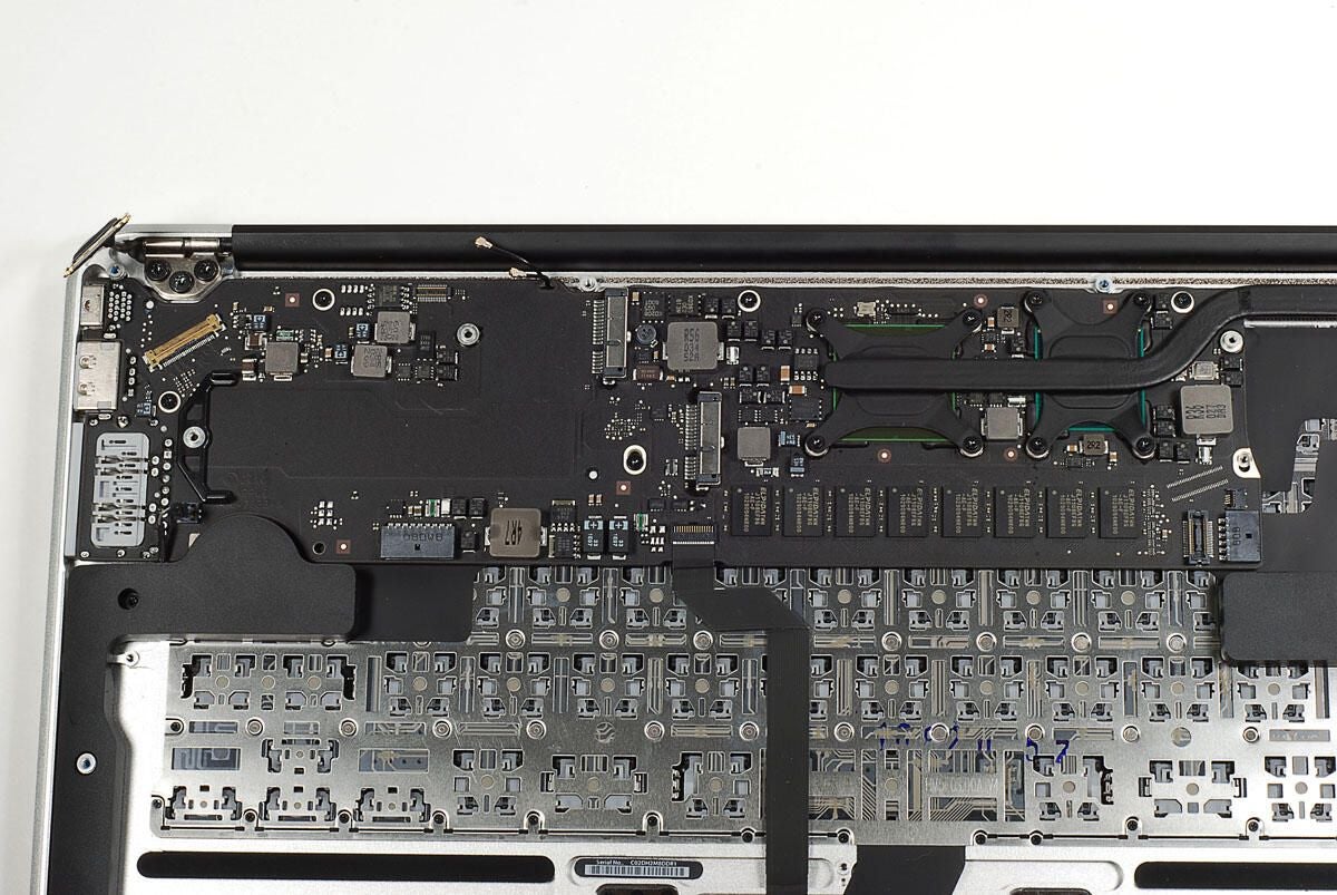
The top of the main logic board contains three main components of the MacBook Air–the Intel Core 2 Duo CPU and NVIDIA GeForce 320M GPU (covered by the heat sink) and Elpida RAM chips.
Photo by: Bill Detwiler / TechRepublic
Caption by: Bill Detwiler
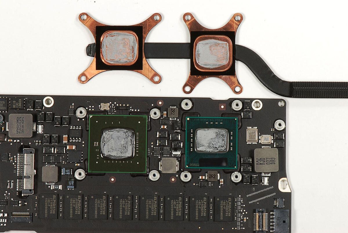
We’ll need to clean the thermal paste from the CPU and GPU for a clear look at the chips.
Photo by: Bill Detwiler / TechRepublic
Caption by: Bill Detwiler
The NVIDIA GPU in located on the left and the Intel CPU is on the right. Let’s take a closer look each chip.
Photo by: Bill Detwiler / TechRepublic
Caption by: Bill Detwiler
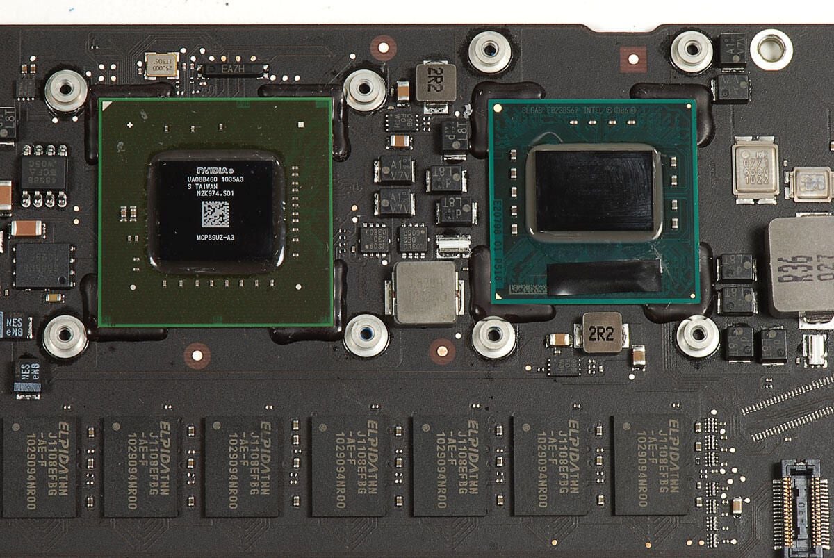
With the thermal paste cleaned off, we can clearly see the marking on the MacBook Air’s NVIDIA GeForce 320M graphics processor.
Photo by: Bill Detwiler / TechRepublic
Caption by: Bill Detwiler
There are no visible marking on the core of our MacBook Air’s Intel Core 2 Duo 1.86 GHz CPU, but there are markings printed onto the chip’s green circuit board.
Photo by: Bill Detwiler / TechRepublic
Caption by: Bill Detwiler
Our MacBook Air came with 2GB of 1066MHz DDR3 SDRAM. Like the previous MacBook Air, the RAM is soldered to the main logic board. Upgrading the Air’s RAM after purchase isn’t possible. As the upgrade from 2GB to 4GB is only $100, I recommend going with the 4GB.
Photo by: Bill Detwiler / TechRepublic
Caption by: Bill Detwiler
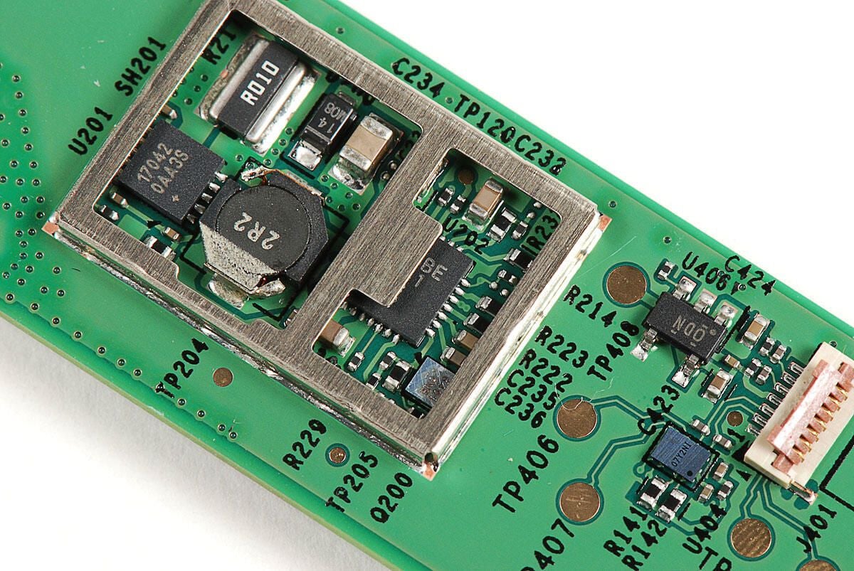
Photo by: Bill Detwiler / TechRepublic
Caption by: Bill Detwiler
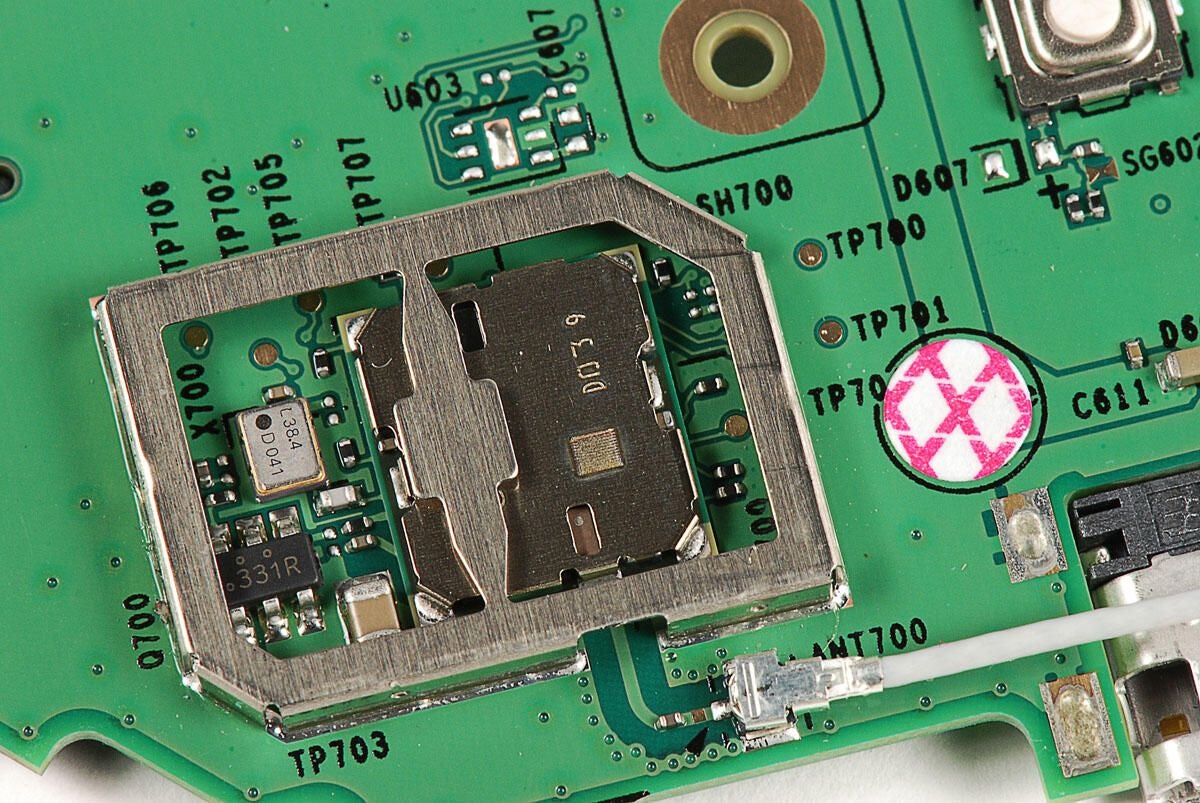
Photo by: Bill Detwiler / TechRepublic
Caption by: Bill Detwiler
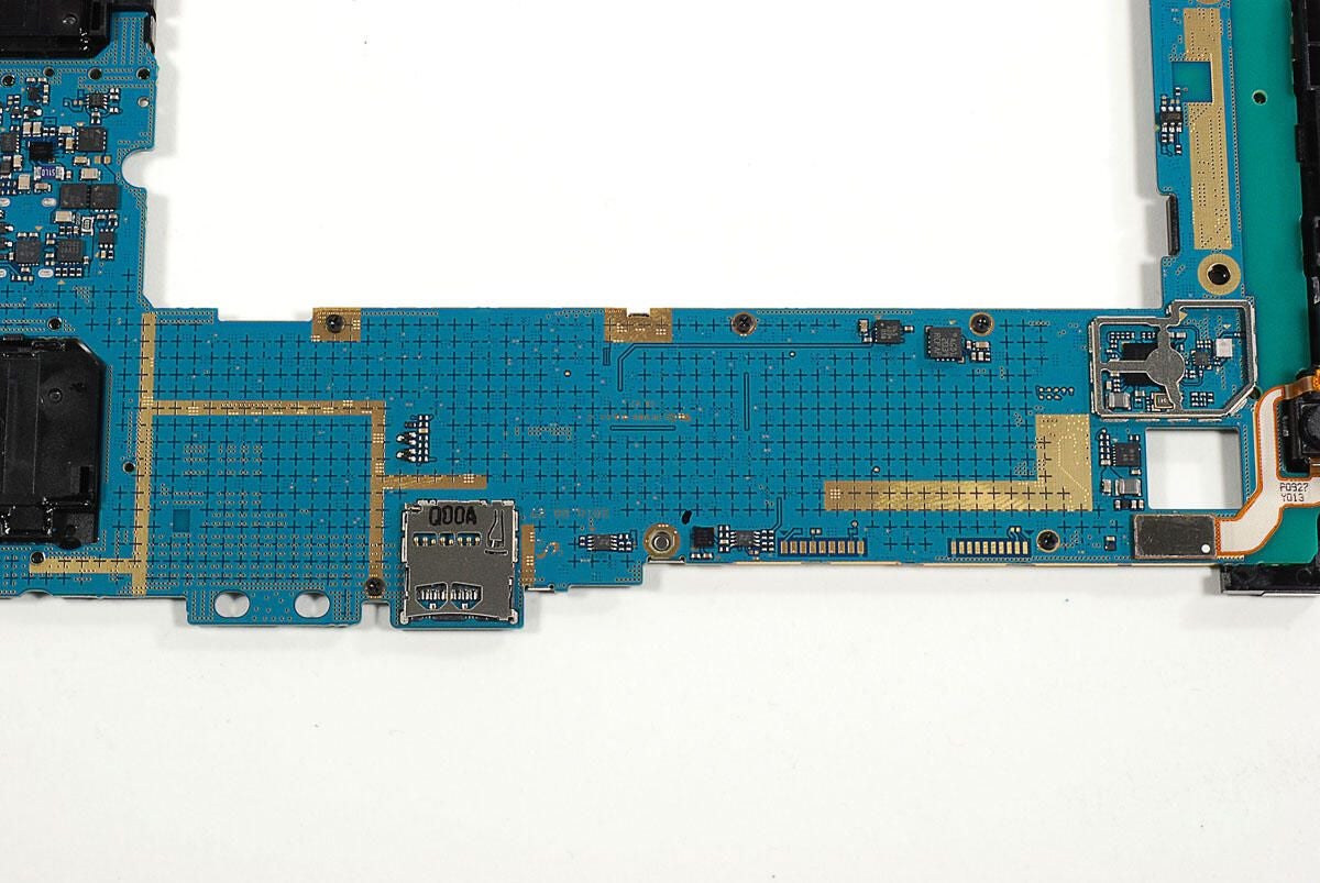
Photo by: Bill Detwiler / TechRepublic
Caption by: Bill Detwiler
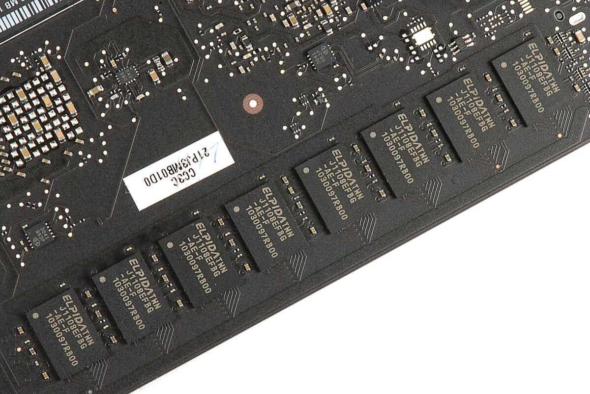
A second set of Elpida RAM chips are located on the bottom of the main logic board.
Photo by: Bill Detwiler / TechRepublic
Caption by: Bill Detwiler
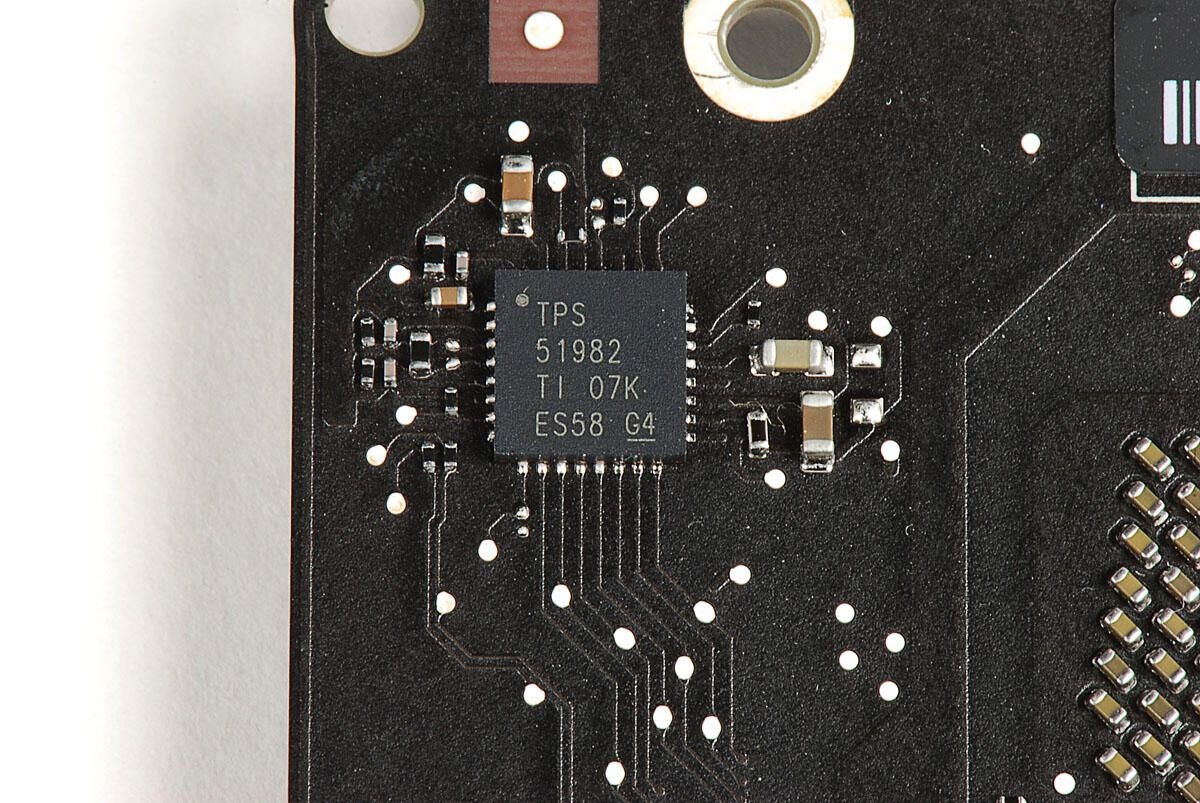
TPS 51982 TI 07K ES5T G4
Photo by: Bill Detwiler / TechRepublic
Caption by: Bill Detwiler
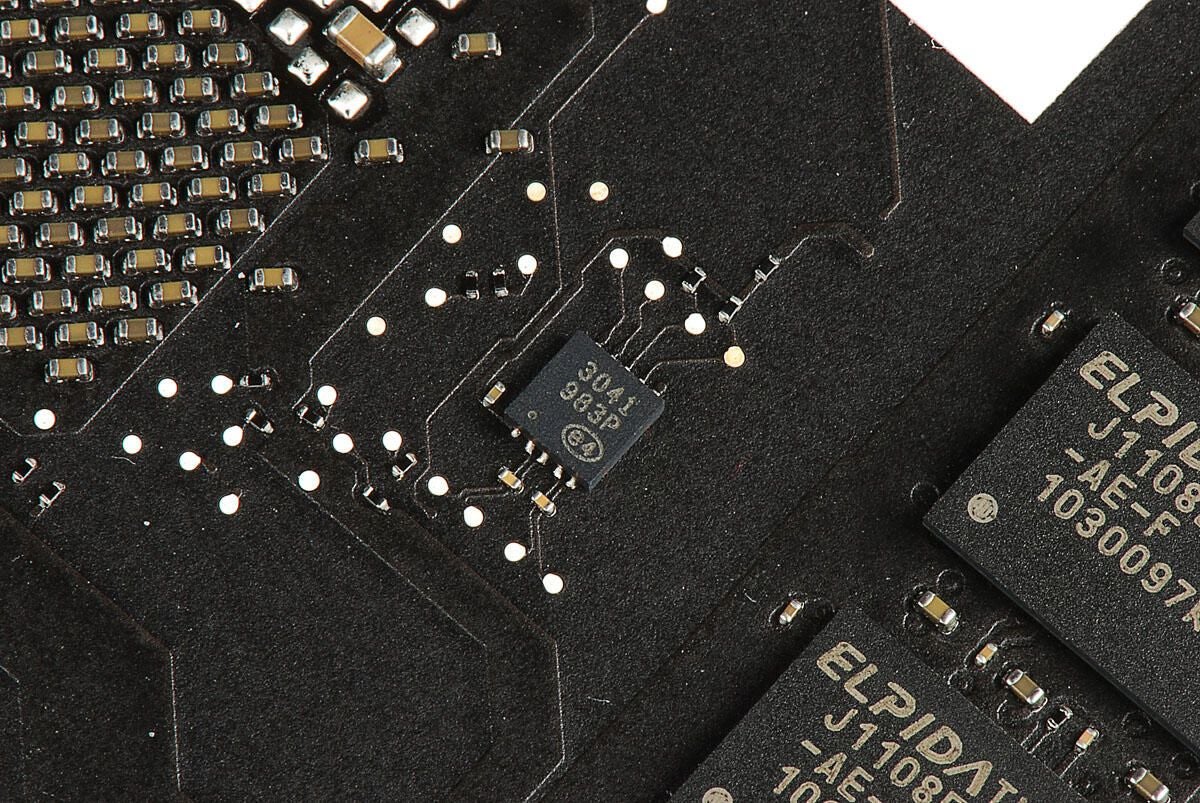
Photo by: Bill Detwiler / TechRepublic
Caption by: Bill Detwiler
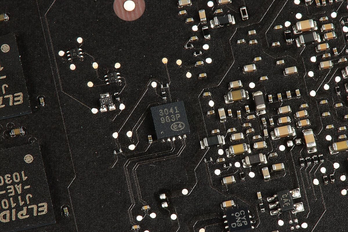
Photo by: Bill Detwiler / TechRepublic
Caption by: Bill Detwiler
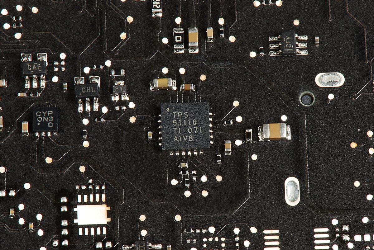
Photo by: Bill Detwiler / TechRepublic
Caption by: Bill Detwiler
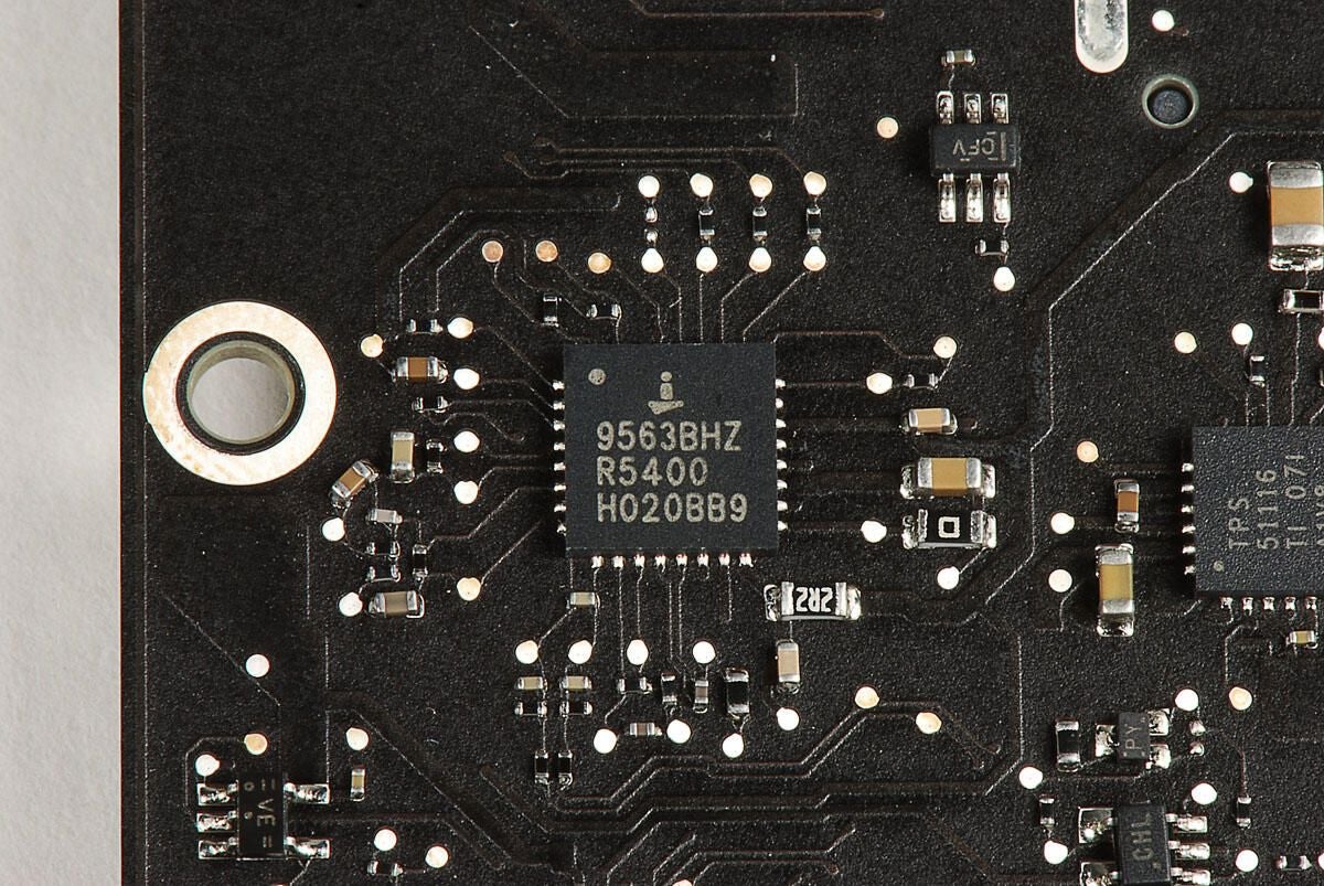
i 9563BHZ R5400 H020BB9
Photo by: Bill Detwiler / TechRepublic
Caption by: Bill Detwiler
Photo by: Bill Detwiler / TechRepublic
Caption by: Bill Detwiler
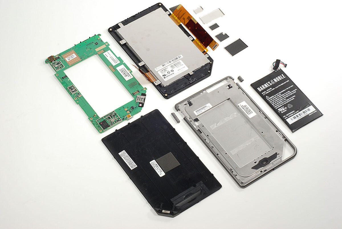
Photo by: Bill Detwiler / TechRepublic
Caption by: Bill Detwiler
Photo by: Bill Detwiler / TechRepublic
Caption by: Bill Detwiler
Photo by: Bill Detwiler / TechRepublic
Caption by: Bill Detwiler
Photo by: Bill Detwiler / TechRepublic
Caption by: Bill Detwiler
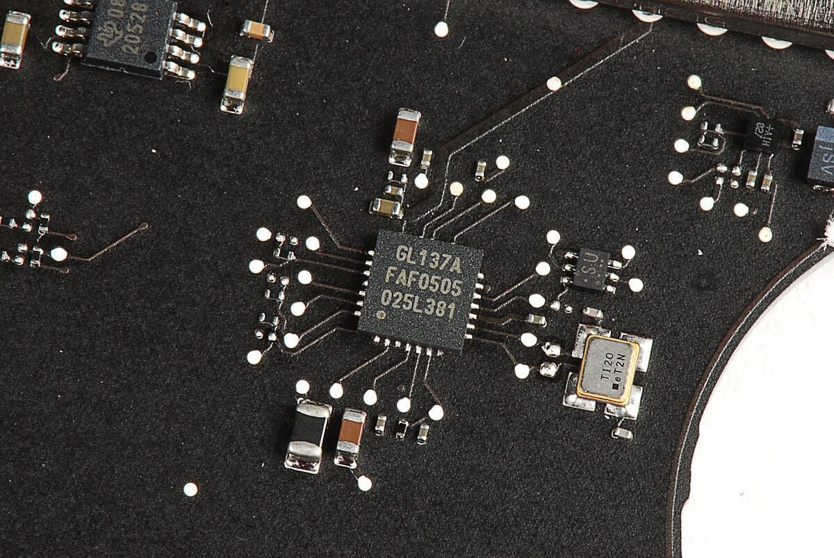
Photo by: Bill Detwiler / TechRepublic
Caption by: Bill Detwiler
Photo by: Bill Detwiler / TechRepublic
Caption by: Bill Detwiler
Photo by: Bill Detwiler / TechRepublic
Caption by: Bill Detwiler
Bill Detwiler is the Editor for Technical Content and Ecosystem at Celonis. He is the former Editor in Chief of TechRepublic and previous host of TechRepublic's Dynamic Developer podcast and Cracking Open, CNET and TechRepublic's popular online show. Previously, Bill was an IT manager in the social research and energy industries. He has bachelor's and master's degrees from the University of Louisville, where he has also lectured on computer crime and crime prevention.
