In November 2010, Boxee and D-Link began shipping the Boxee Box by D-Link Internet TV set-top box. Follow along as I crack open the Boxee Box for a look at the hardware inside.
To see how the Boxee Box compares against other Internet TV set-top boxes, read Jason Hiner’s review of the Apple TV, Roku Player, and Google TV, the Boxee Box. And don’t forget to check out our cracking open gallery of the 2010 Apple TV.
Photo by: Bill Detwiler / TechRepublic
Caption by: Bill Detwiler
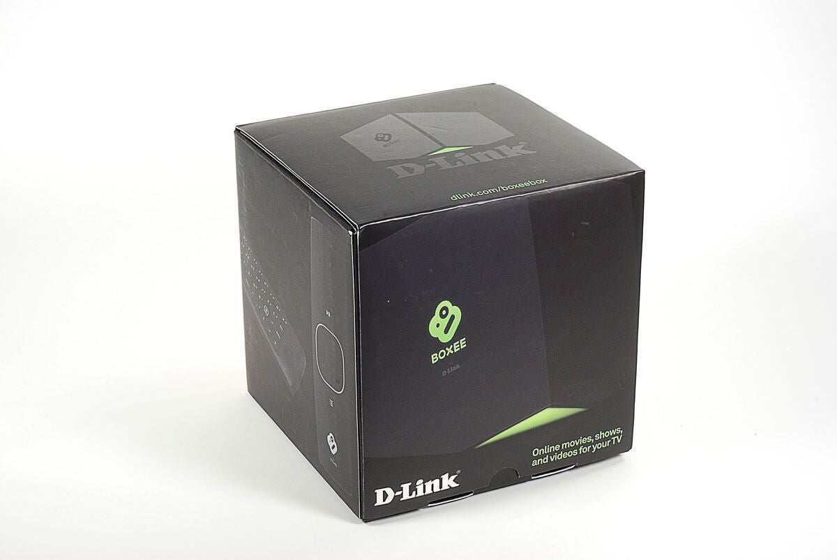
The Boxee Box by D-Link retails for $199 (US) and as of this writing, the unit offers content from Netflix, MLB, NHL, Vodo, Pandora, and a variety of online sources like YouTube. The Boxee Box also has a built-in browser that can play Flash video and supports a wide range of video and audio files–making it easy to play content stored on your own network.
Photo by: Bill Detwiler / TechRepublic
Caption by: Bill Detwiler
Photo by: Bill Detwiler / TechRepublic
Caption by: Bill Detwiler
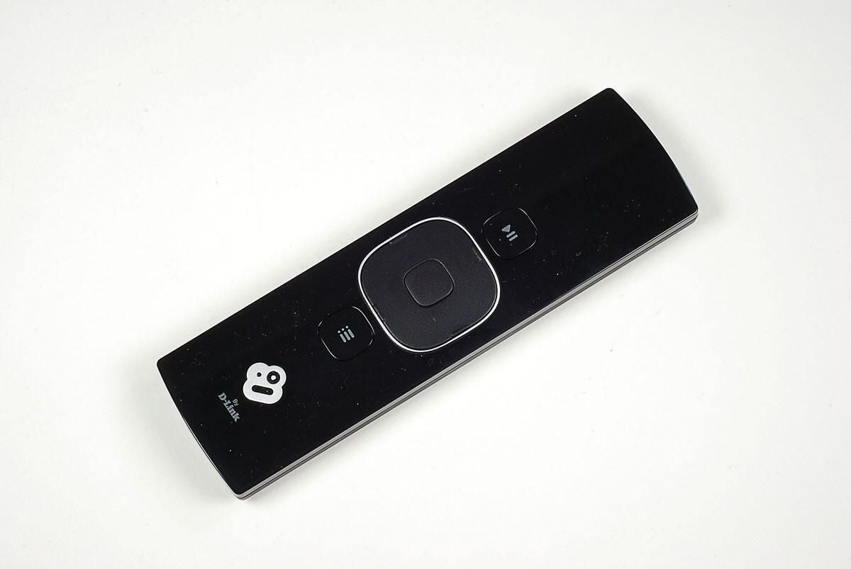
On top of the Boxee Box remote are a play/pause button, directional pad, enter button, and menu button.
Photo by: Bill Detwiler / TechRepublic
Caption by: Bill Detwiler
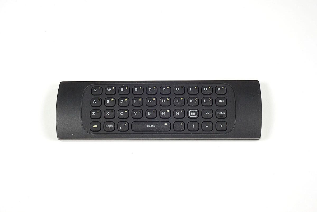
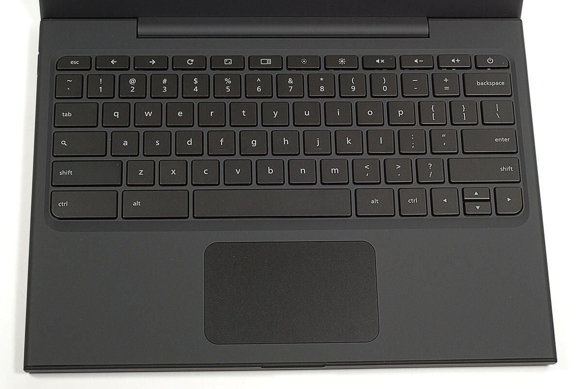
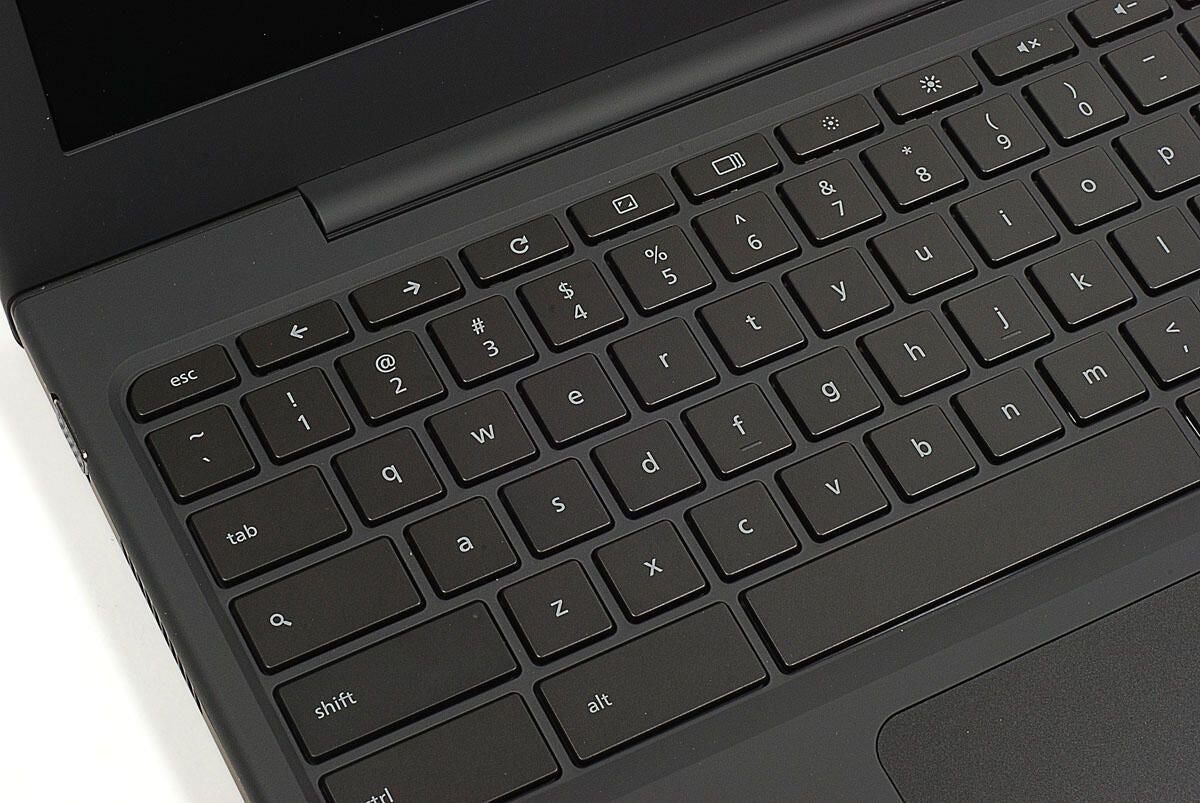
Flip the Boxee Box remote over, and you’ll find a QWERTY keypad. This is a very nice touch.
Photo by: Bill Detwiler / TechRepublic
Caption by: Bill Detwiler
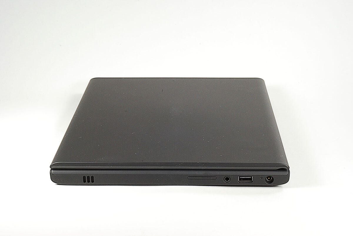
Along the right side of the Boxee Box is an SD/MMC card slot.
Photo by: Bill Detwiler / TechRepublic
Caption by: Bill Detwiler
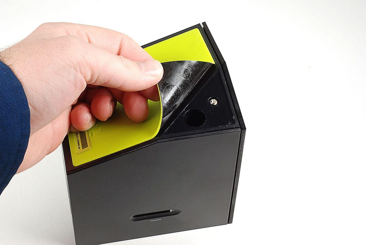
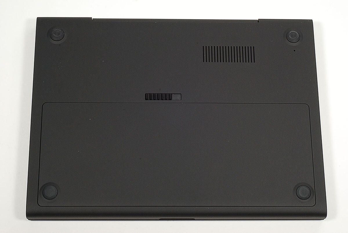
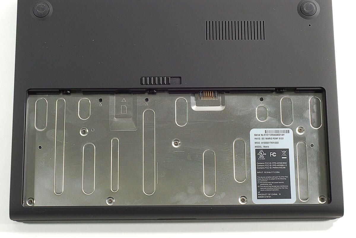
To access the case screws, we must remove the lime-green, rubber pad from the base of the Boxee Box.
Photo by: Bill Detwiler / TechRepublic
Caption by: Bill Detwiler
Under the rubber pad is a second black, plastic sheet that’s also stuck to the bottom of the Boxee Box. You’ll also need to remove it.
Photo by: Bill Detwiler / TechRepublic
Caption by: Bill Detwiler
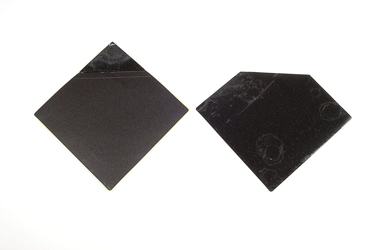
Photo by: Bill Detwiler / TechRepublic
Caption by: Bill Detwiler
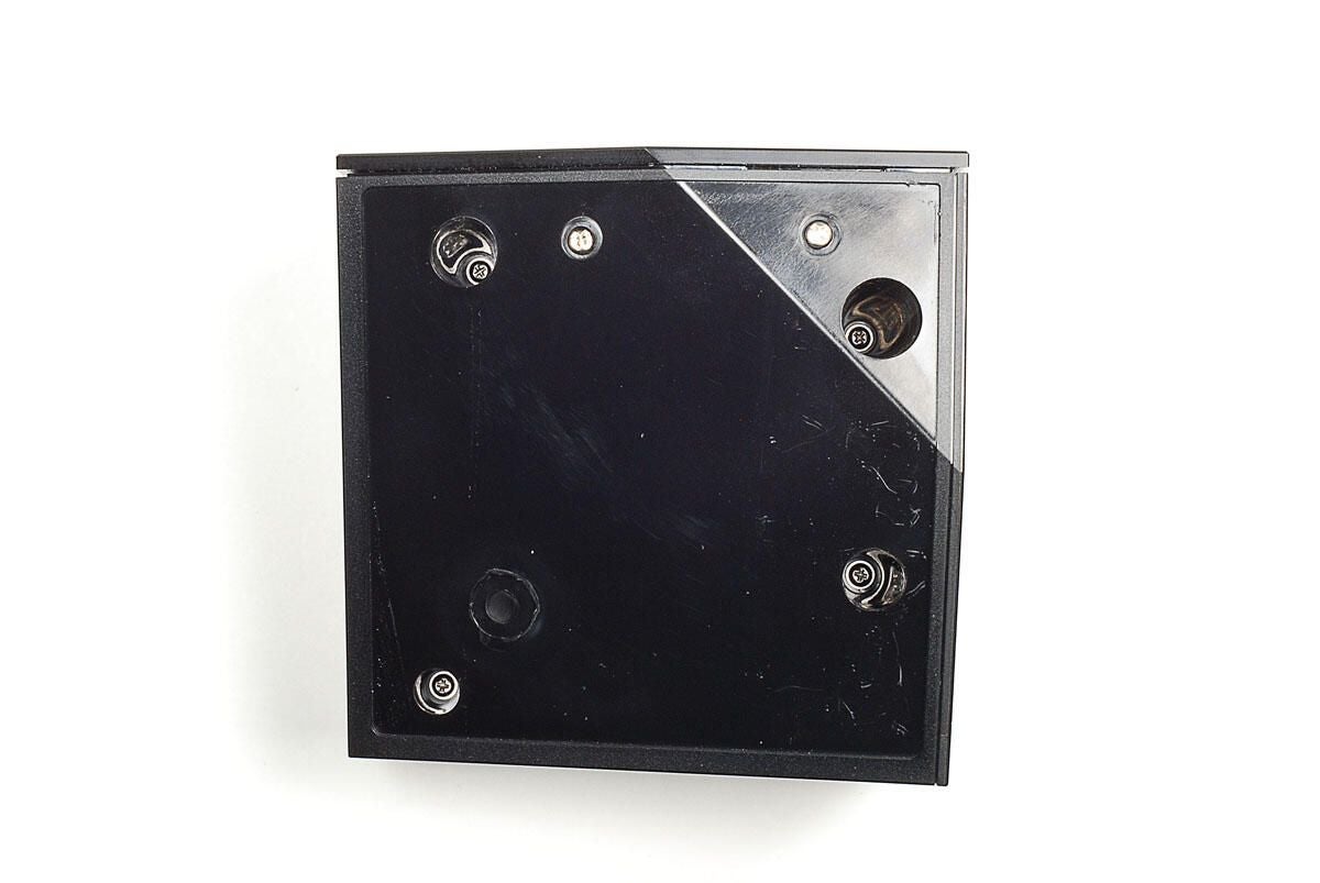
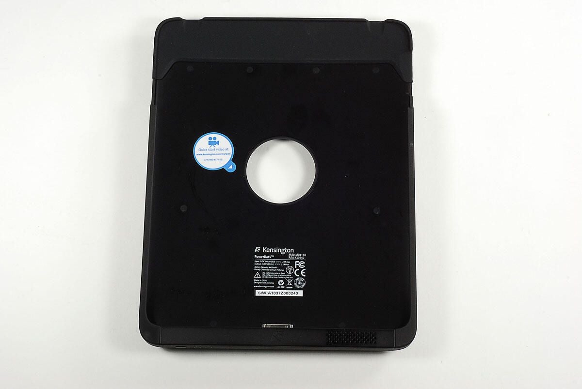
With the lime-green pad and plastic sheet removed, we can see the six Phillips screws that secure the Boxee Box’s external shell. Two of the screws are located near the outer edge of the base. While, the other four are recessed inside the plastic base.
Photo by: Bill Detwiler / TechRepublic
Caption by: Bill Detwiler
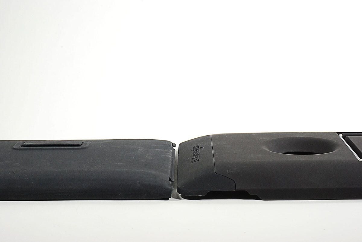
With all six screws removed, you can lift the base section of the Boxee Box’s case away from the other half.
Photo by: Bill Detwiler / TechRepublic
Caption by: Bill Detwiler
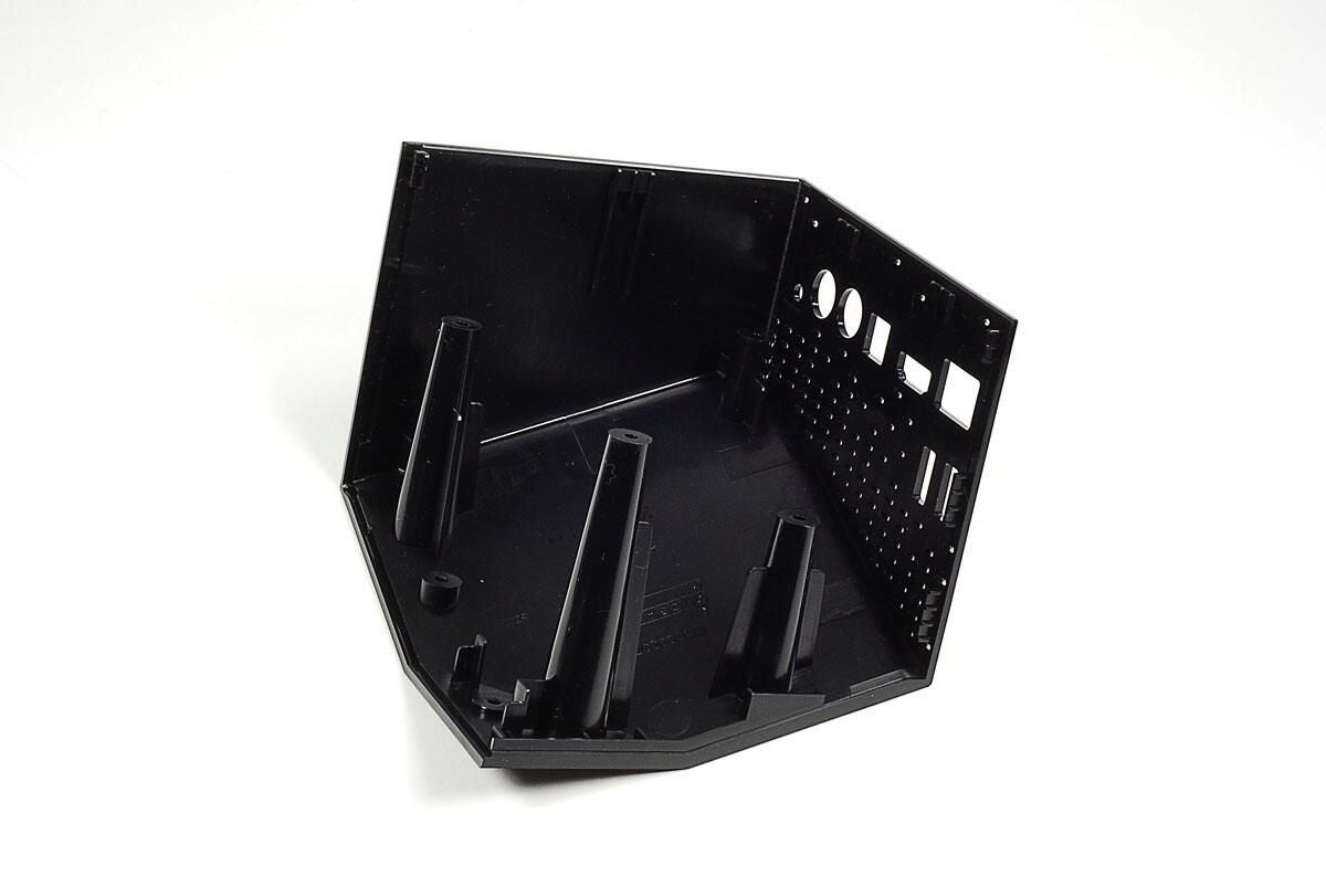
Photo by: Bill Detwiler / TechRepublic
Caption by: Bill Detwiler
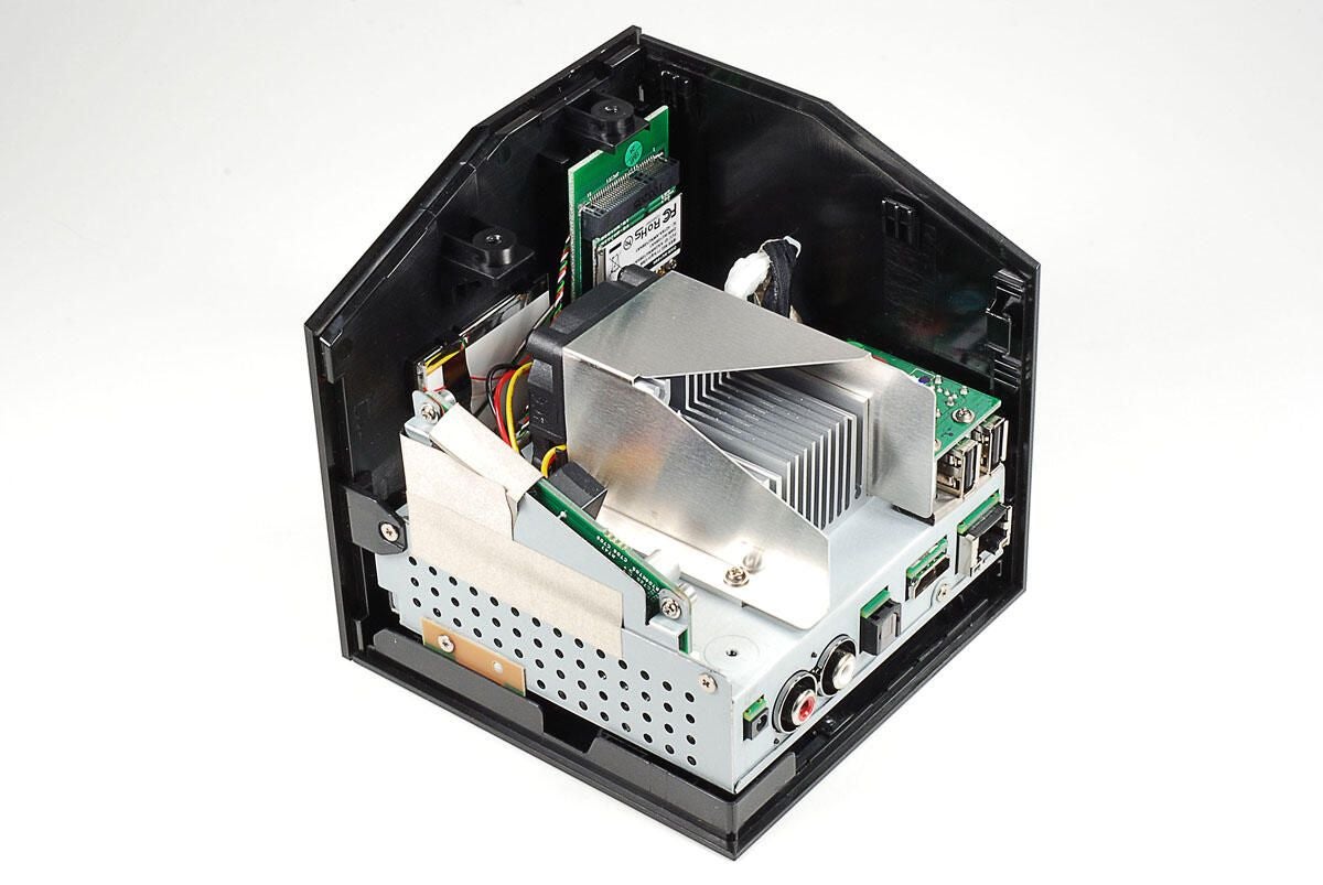
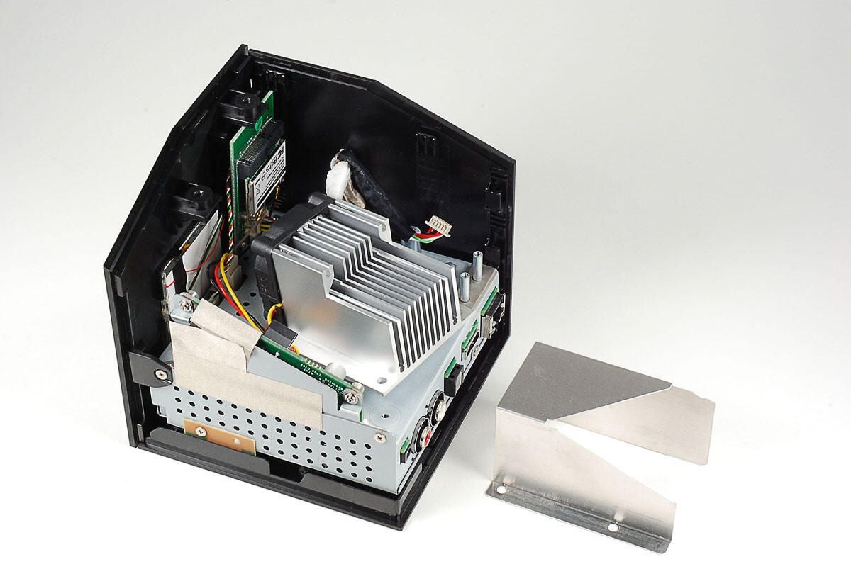
With the base section of the Boxee Box’s outer shell removed, we get our first look inside D-Link’s set-top box. Immediately visible is the large heatsink and cooling fan. An oddly-shaped power board rises up from the main PCB (hidden within the internal metal case). The wireless card is located behind the cooling assembly. And, a small PCB with the USB ports is located to the right of the heatsink and fan.
Photo by: Bill Detwiler / TechRepublic
Caption by: Bill Detwiler
Photo by: Bill Detwiler / TechRepublic
Caption by: Bill Detwiler
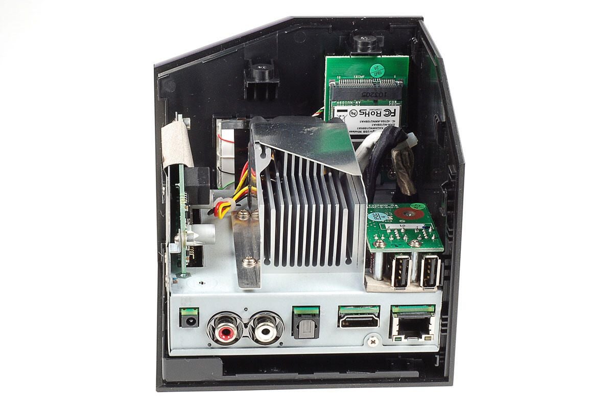
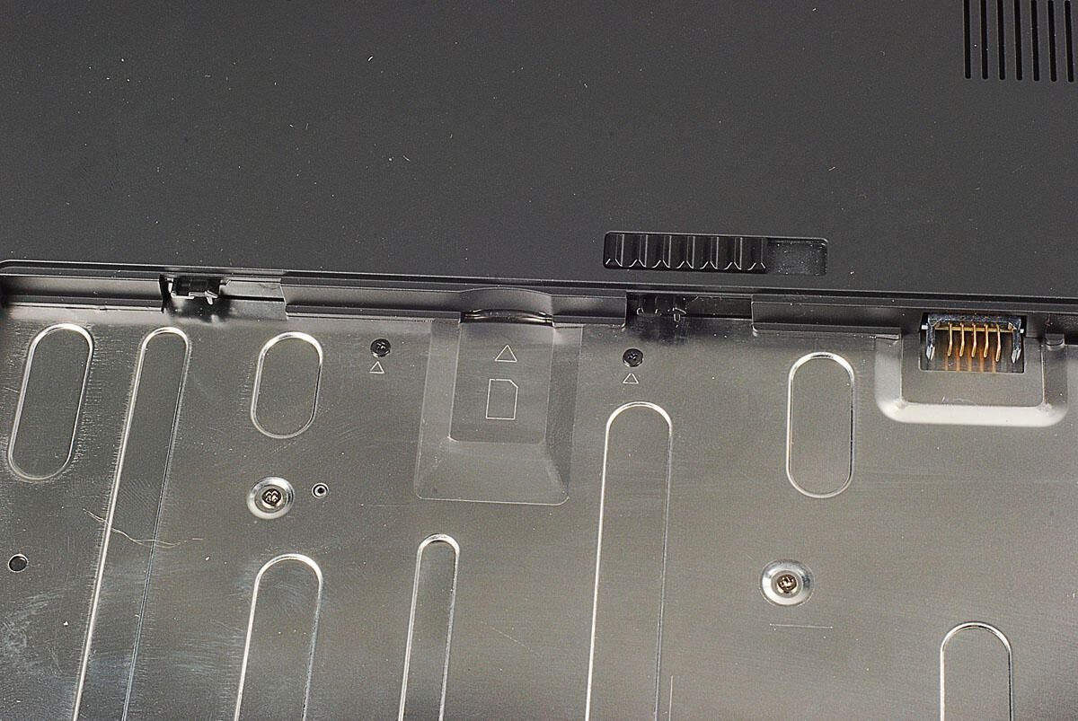
Although the Boxee Box’s odd shape makes it difficult to tell which end is up, the internal components are actually secured to the top of the unit.
Photo by: Bill Detwiler / TechRepublic
Caption by: Bill Detwiler
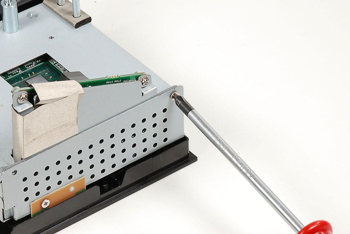
Next, you’ll need to remove the small PCB that houses the unit’s two USB ports. It is held to the Boxee Box’s internal metal frame with two Phillips screws. Before removing the USB PCB, you’ll also need to disconnect the cable that attaches it to the main PCB.
Photo by: Bill Detwiler / TechRepublic
Caption by: Bill Detwiler
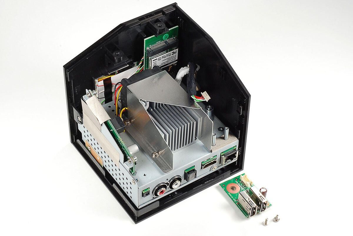
Photo by: Bill Detwiler / TechRepublic
Caption by: Bill Detwiler
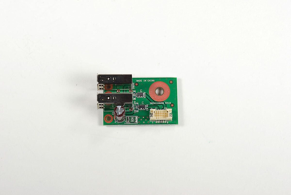
Photo by: Bill Detwiler / TechRepublic
Caption by: Bill Detwiler
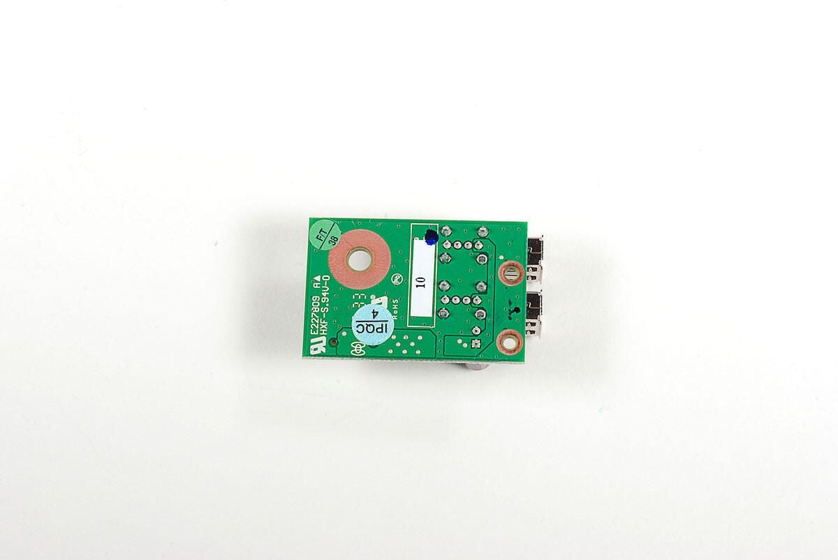
Photo by: Bill Detwiler / TechRepublic
Caption by: Bill Detwiler
With the small USB PCB removed, we can more easily access the four Phillips screws that hold the heatsink/fan assembly and its metal shroud.
Photo by: Bill Detwiler / TechRepublic
Caption by: Bill Detwiler
A thin metal shroud cover part of the heatsink and fan assembly. You’ll need to disconnect the fan’s cable before lifting it away from the Boxee Box.
Photo by: Bill Detwiler / TechRepublic
Caption by: Bill Detwiler
The Boxee Box’s heatsink uses a phase change thermal pad instead of thermal paste to conduct heat away from the CPU.
Photo by: Bill Detwiler / TechRepublic
Caption by: Bill Detwiler
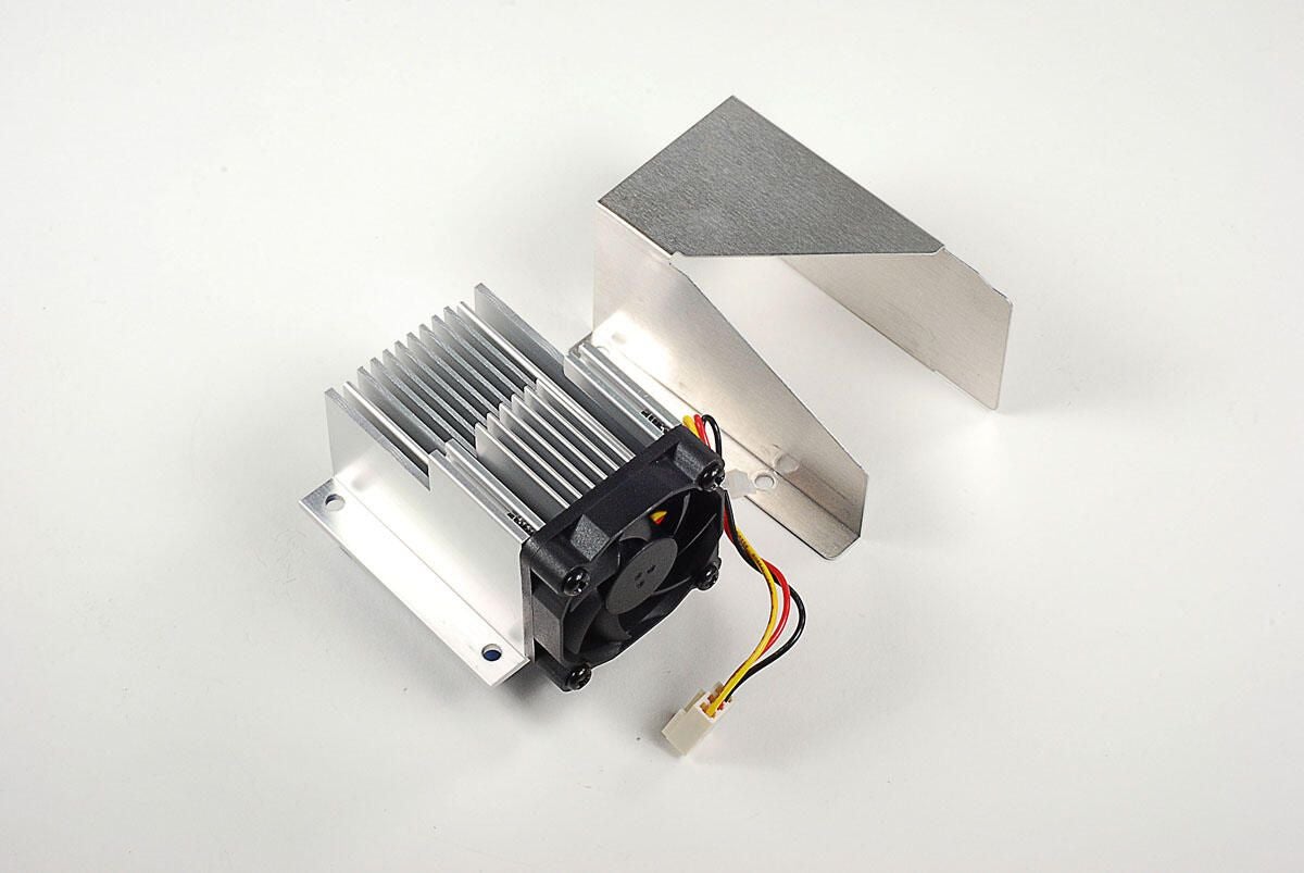
Photo by: Bill Detwiler / TechRepublic
Caption by: Bill Detwiler
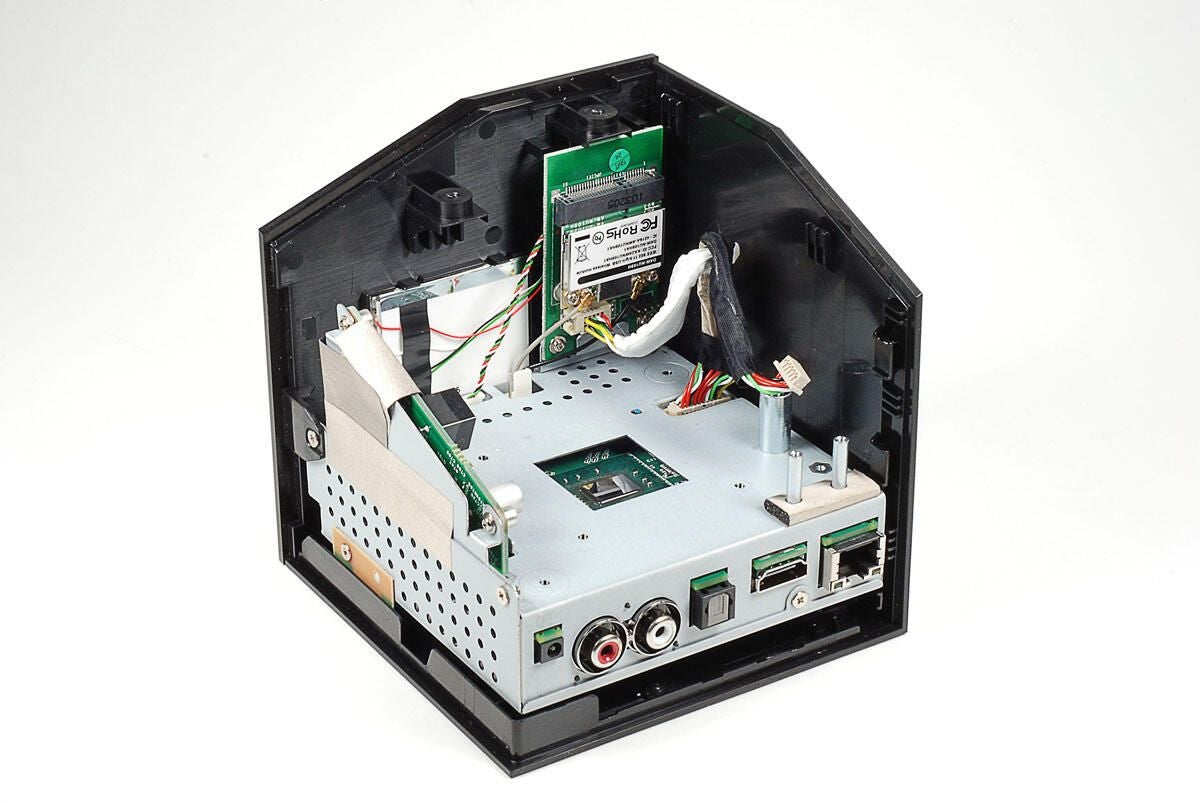
Photo by: Bill Detwiler / TechRepublic
Caption by: Bill Detwiler
The Boxee Box’s wireless PCB is next on our removal list. Two Phillips screws hold it in place. You’ll also need to disconnect the two antenna wires and the large cable before lifting it away from the rest of the unit.
Photo by: Bill Detwiler / TechRepublic
Caption by: Bill Detwiler

Photo by: Bill Detwiler / TechRepublic
Caption by: Bill Detwiler
The wireless card is actually made oup of two PCBs–the larger board that connects directly to the main PCB via a cable and a smaller wireless PCB that provides the 802.11 b/g/n support. The smaller PCB is held to the larger with two Phillips screws.
Photo by: Bill Detwiler / TechRepublic
Caption by: Bill Detwiler
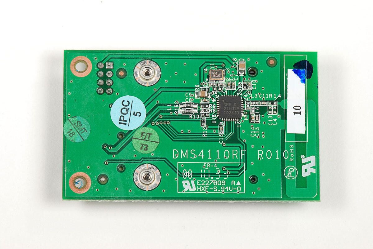
On the underside of the is a Nordic Semiconductor nRF24LU1 single chip 2.4GHz Tranceiver with USB Microcontroller and Flash Memory.
Photo by: Bill Detwiler / TechRepublic
Caption by: Bill Detwiler
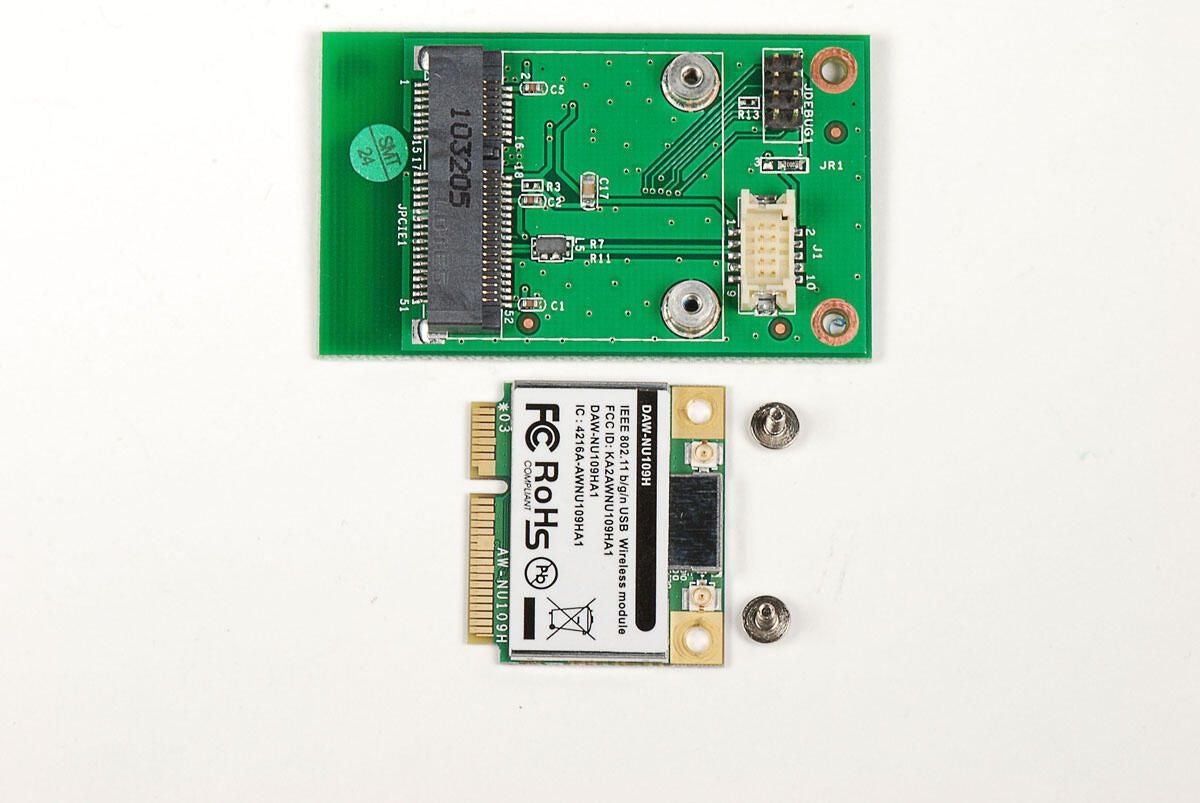
Photo by: Bill Detwiler / TechRepublic
Caption by: Bill Detwiler
With the EMI shield removed, we can see a a few of the chips on the 802.11 b/g/n card. Unfortunately, our view of the main chip is blocked by a metal cross beam on the EMI shield’s base. As I want to reassemble this unit in working order, I’m not going to cut the beam away from the card.
Photo by: Bill Detwiler / TechRepublic
Caption by: Bill Detwiler
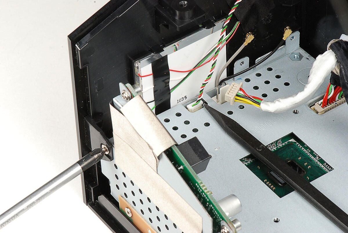
We can now remove the front panel of the Boxee Box’s external case. It is held in place by a single Phillips screw. Before removing the panel, you’ll also need to disconnect the thin wire that runs from the main PCB to the large, rectangular LED panel mounted to the inside of the panel. This LED panel illuminates the Boxee logo on the front panel when the unit it powered on.
Photo by: Bill Detwiler / TechRepublic
Caption by: Bill Detwiler
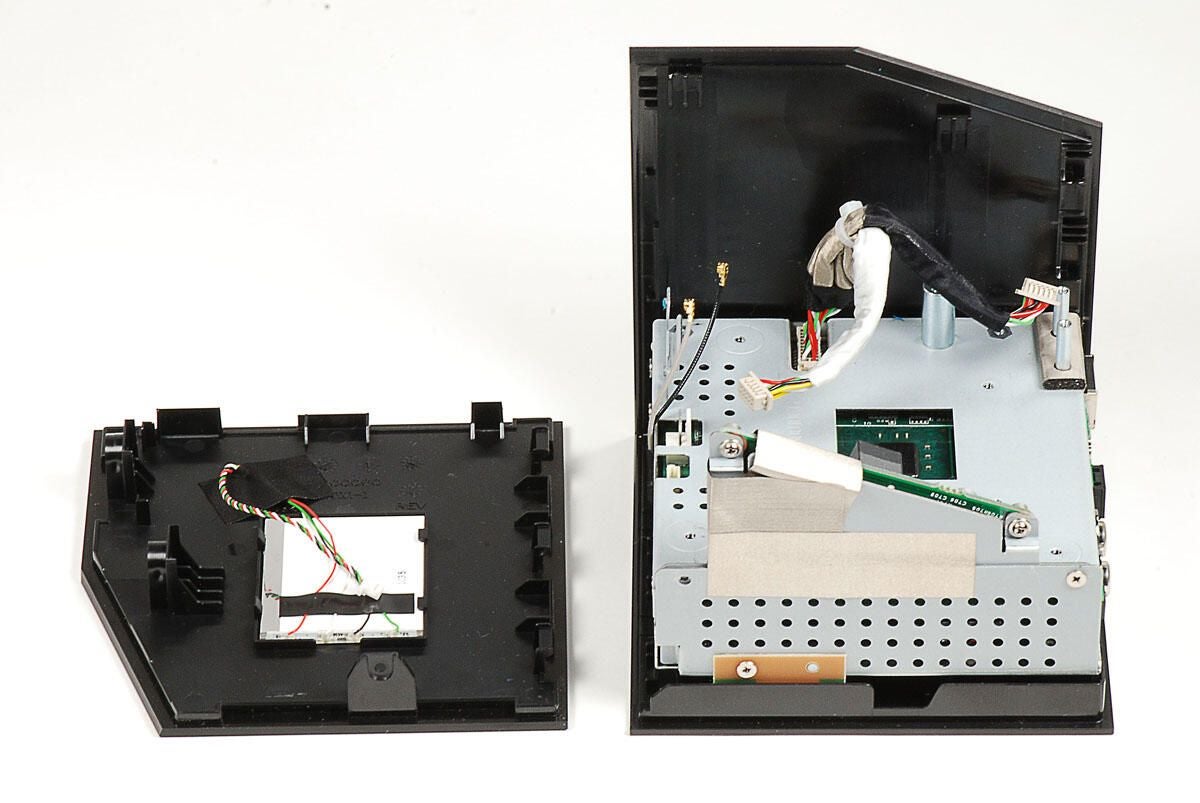
Photo by: Bill Detwiler / TechRepublic
Caption by: Bill Detwiler
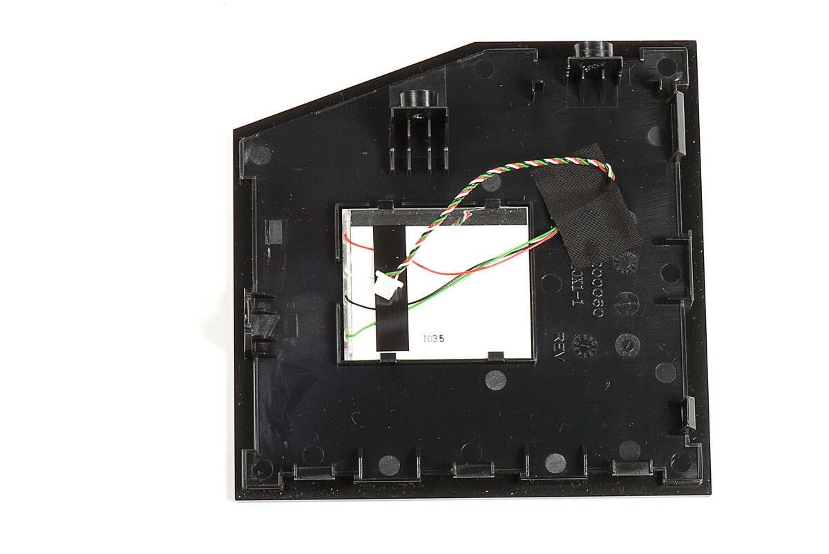
Photo by: Bill Detwiler / TechRepublic
Caption by: Bill Detwiler
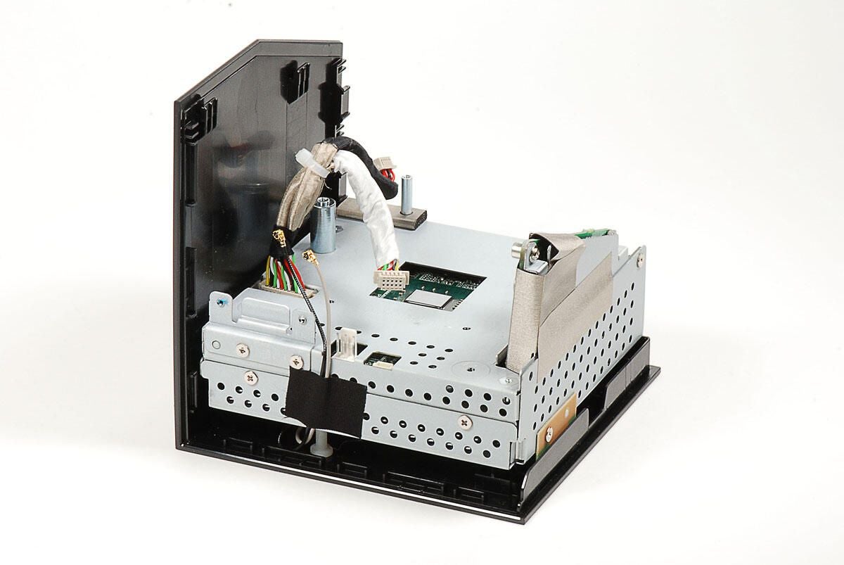
Photo by: Bill Detwiler / TechRepublic
Caption by: Bill Detwiler
This Y-shaped cable connects both the small USB PCB and wireless PCB to the Boxee Box’s main PCB (hidden inside the internal metal frame).
Photo by: Bill Detwiler / TechRepublic
Caption by: Bill Detwiler
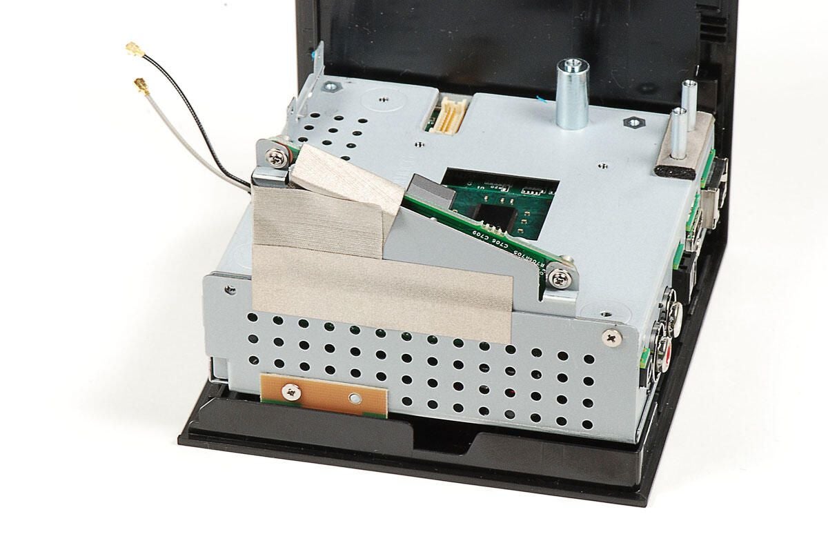
Two pieces of metal tape are attached to both the power board and the metal frame. I’m going to remove the long, horizontal piece at this point. I’ll remove the other piece later, when I remove the power board.
Photo by: Bill Detwiler / TechRepublic
Caption by: Bill Detwiler
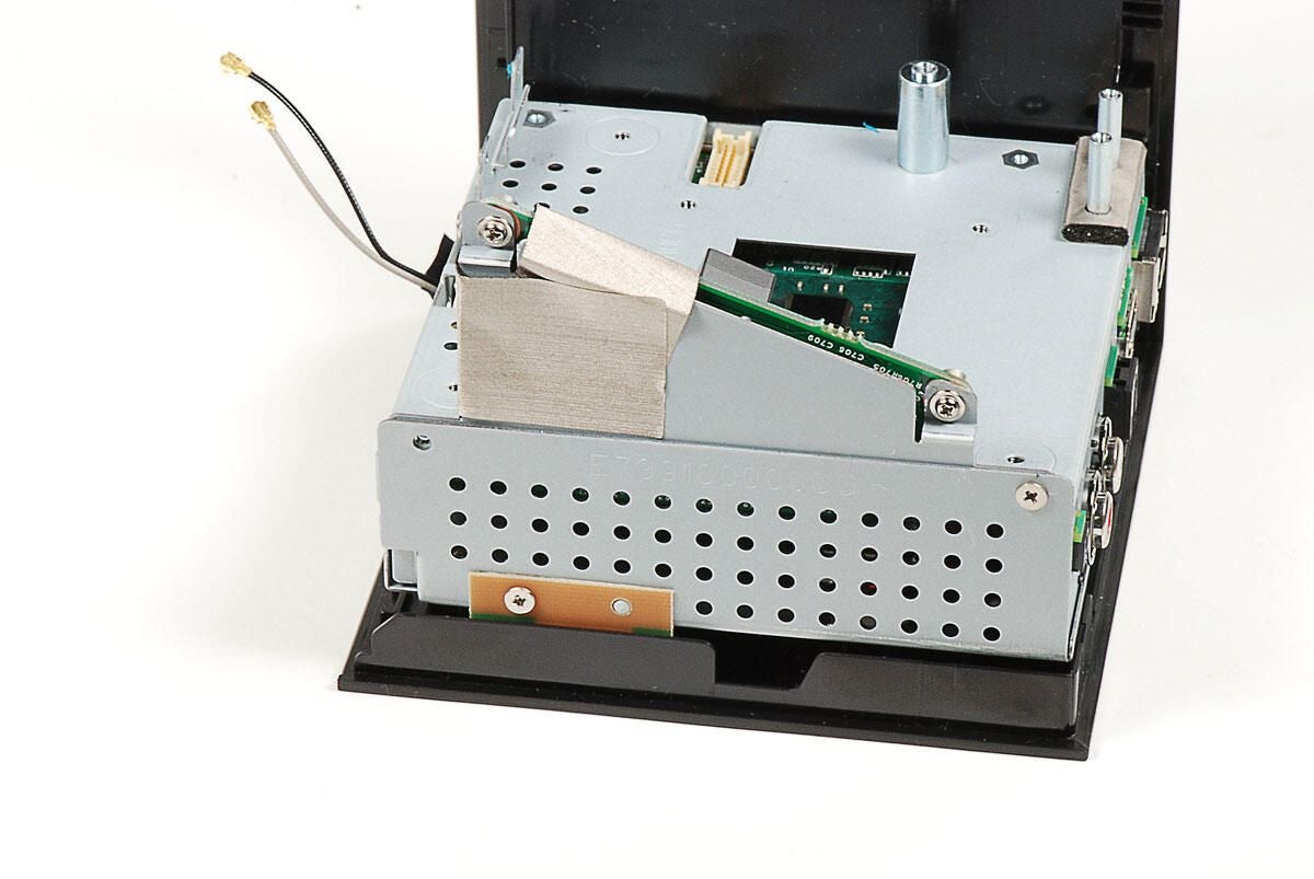
Photo by: Bill Detwiler / TechRepublic
Caption by: Bill Detwiler
Four Phillips screws hold the metal frame’s top and bottom halves together. One screw is located below the power board.
Photo by: Bill Detwiler / TechRepublic
Caption by: Bill Detwiler
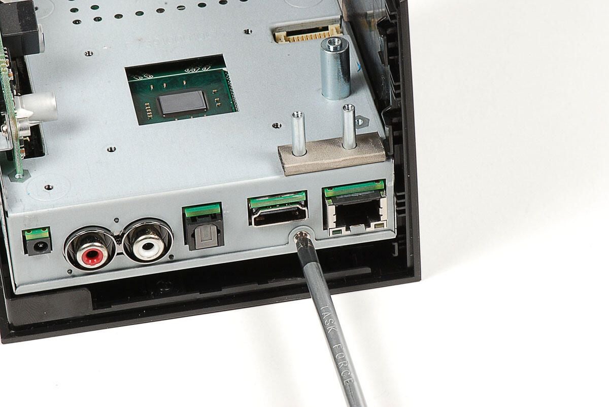
A second screw is located below the ports.
Photo by: Bill Detwiler / TechRepublic
Caption by: Bill Detwiler
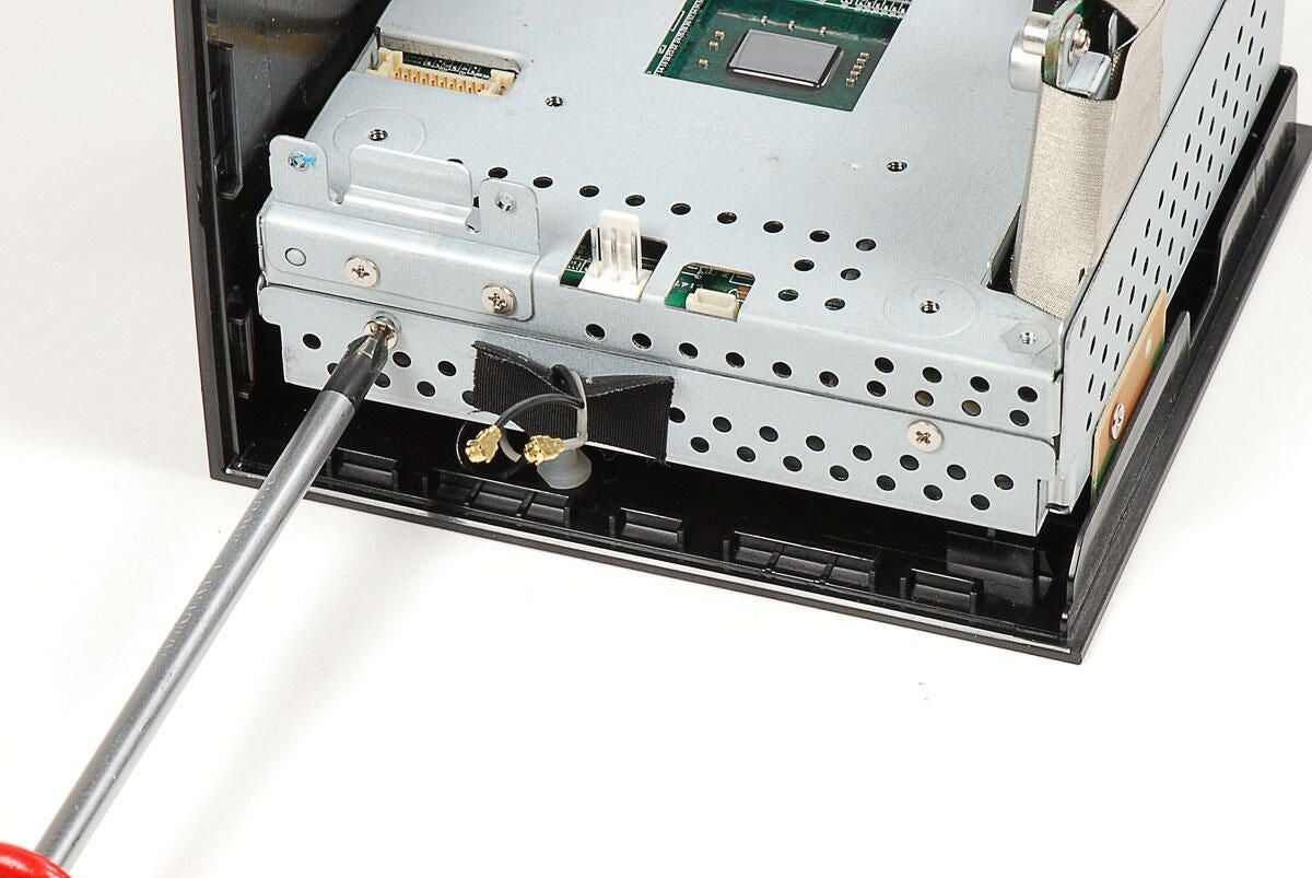
And, two screws are located on what would be the front of the Boxee Box.
Photo by: Bill Detwiler / TechRepublic
Caption by: Bill Detwiler
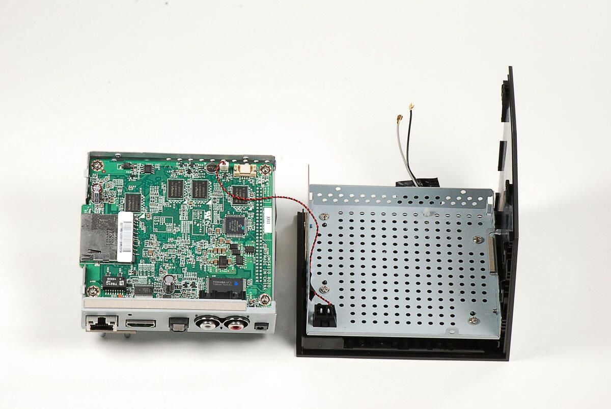
With the four Phillips screws removed, you can separate the two halves of the Boxee Box’s internal metal frame. The main PCB and power board are still attached to the top half of the frame. We’ll remove those in a bit.
Photo by: Bill Detwiler / TechRepublic
Caption by: Bill Detwiler
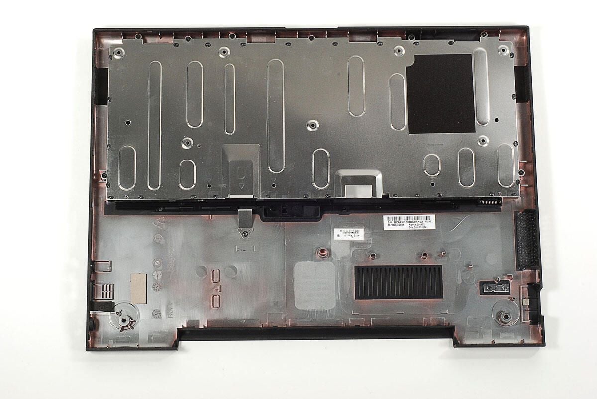
The bottom half of the Boxee Box’s internal metal frame is secured to the outer shell with several Phillips screws. As there’s nothing left to remove from the frame, I’m going to leave it attached to the outer shell.
Photo by: Bill Detwiler / TechRepublic
Caption by: Bill Detwiler
Next, we’ll remove the Boxee Box’s oddly-shaped power board.
Photo by: Bill Detwiler / TechRepublic
Caption by: Bill Detwiler
Before removing the power board, you’ll need to remove the thin, metal tape the runs over the board and metal frame. The tape helps reduce EMI inside the Boxee Box.
Photo by: Bill Detwiler / TechRepublic
Caption by: Bill Detwiler
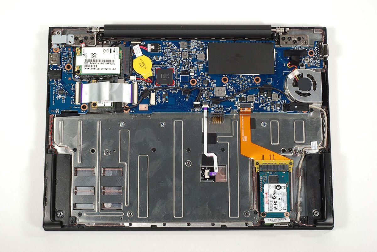
Photo by: Bill Detwiler / TechRepublic
Caption by: Bill Detwiler
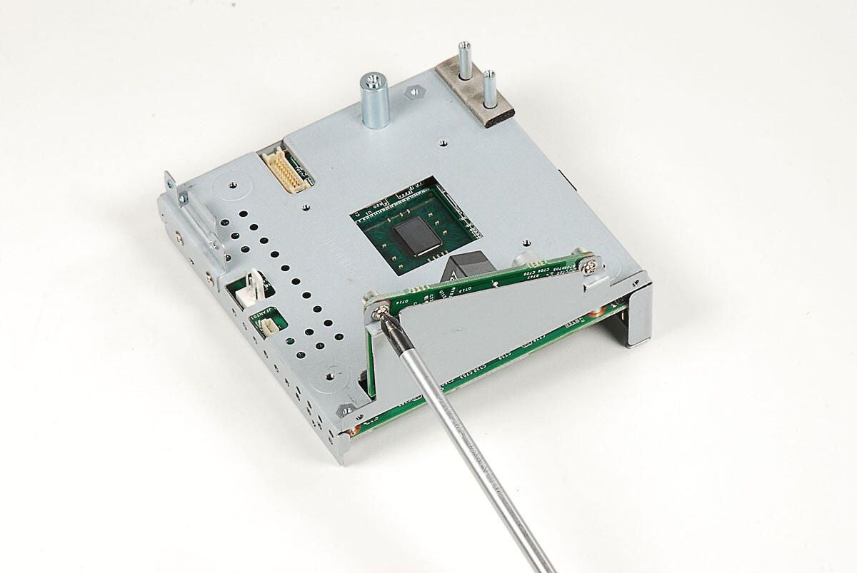
The Boxee Box’s power board is held to the metal frame with two Phillips screws.
Photo by: Bill Detwiler / TechRepublic
Caption by: Bill Detwiler
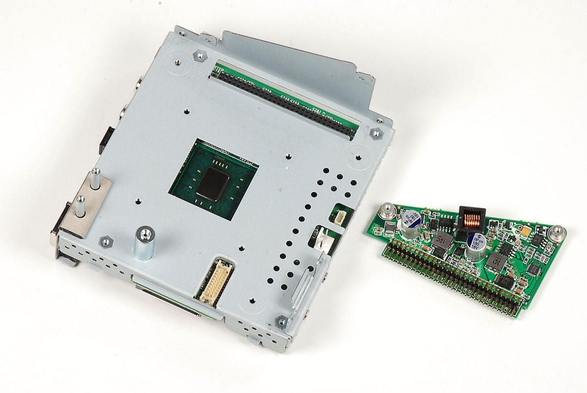
With the screws removed, you can disconnect the power board from the main PCB. I was able to pry up from the bottom of the power board through a slot in the metal frame.
Photo by: Bill Detwiler / TechRepublic
Caption by: Bill Detwiler
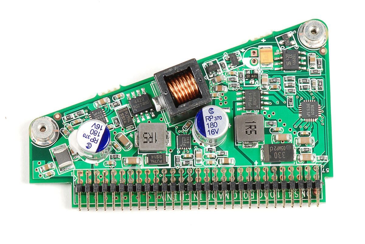
Photo by: Bill Detwiler / TechRepublic
Caption by: Bill Detwiler
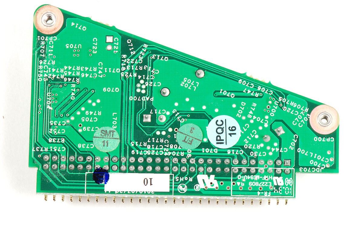
Photo by: Bill Detwiler / TechRepublic
Caption by: Bill Detwiler
Four Phillips screws hold the Boxee Box’s main PCB to the top half of the metal frame.
Photo by: Bill Detwiler / TechRepublic
Caption by: Bill Detwiler
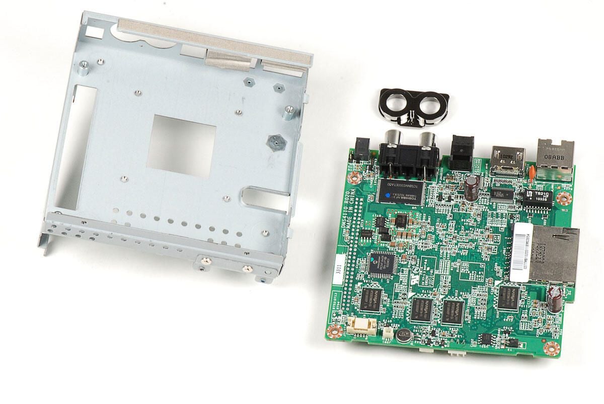
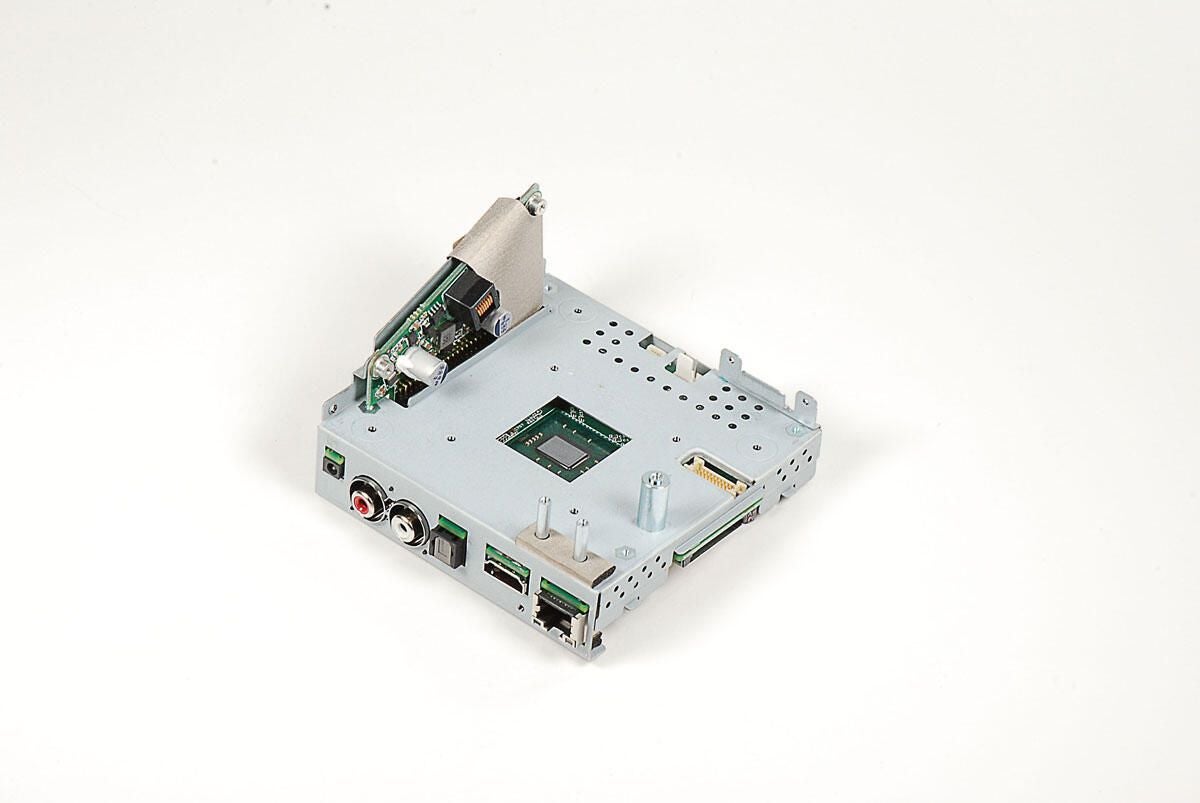
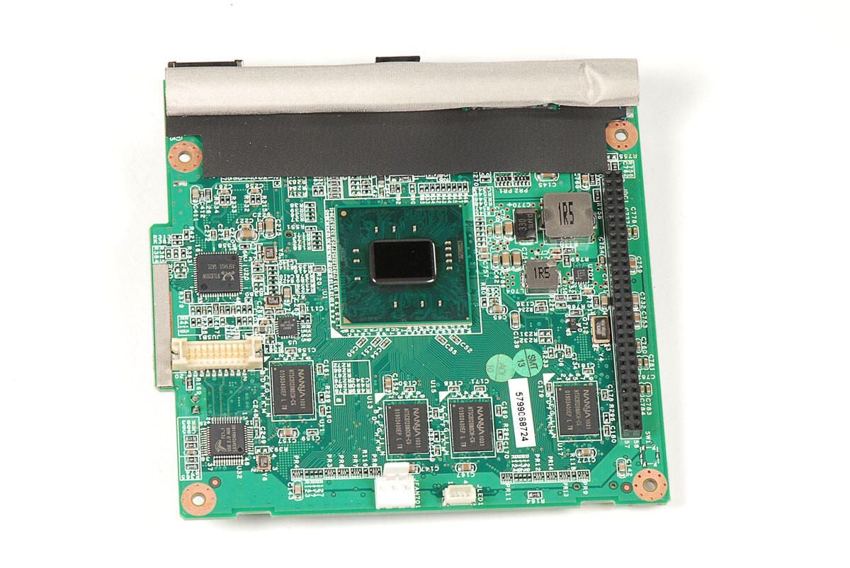
With the screws removed, you can lift the Boxee Box’s main PCB away from the top half of the internal metal frame. You’ll need to first lift the end opposite the ports and then pull the port end out.
A thick cushion is taped to the top of the main PCB above the ports. The cushion makes the board a bit difficult to remove, but with a little effort the board should separate from the frame. Take note when removing the PCB, a plastic sleeve sits between the two RCA audio outs and the metal frame. It will likely come loose when you remove the main PCB.
Photo by: Bill Detwiler / TechRepublic
Caption by: Bill Detwiler
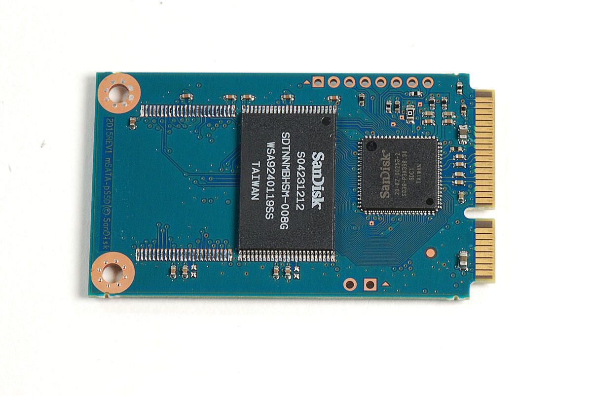
Photo by: Bill Detwiler / TechRepublic
Caption by: Bill Detwiler
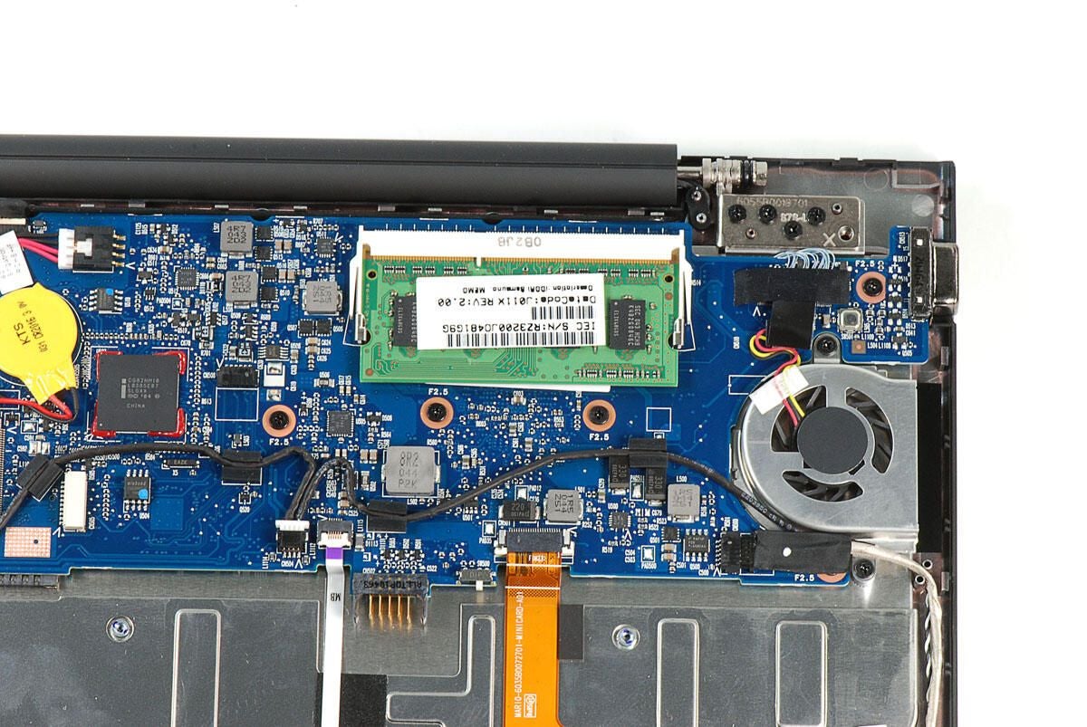
Photo by: Bill Detwiler / TechRepublic
Caption by: Bill Detwiler
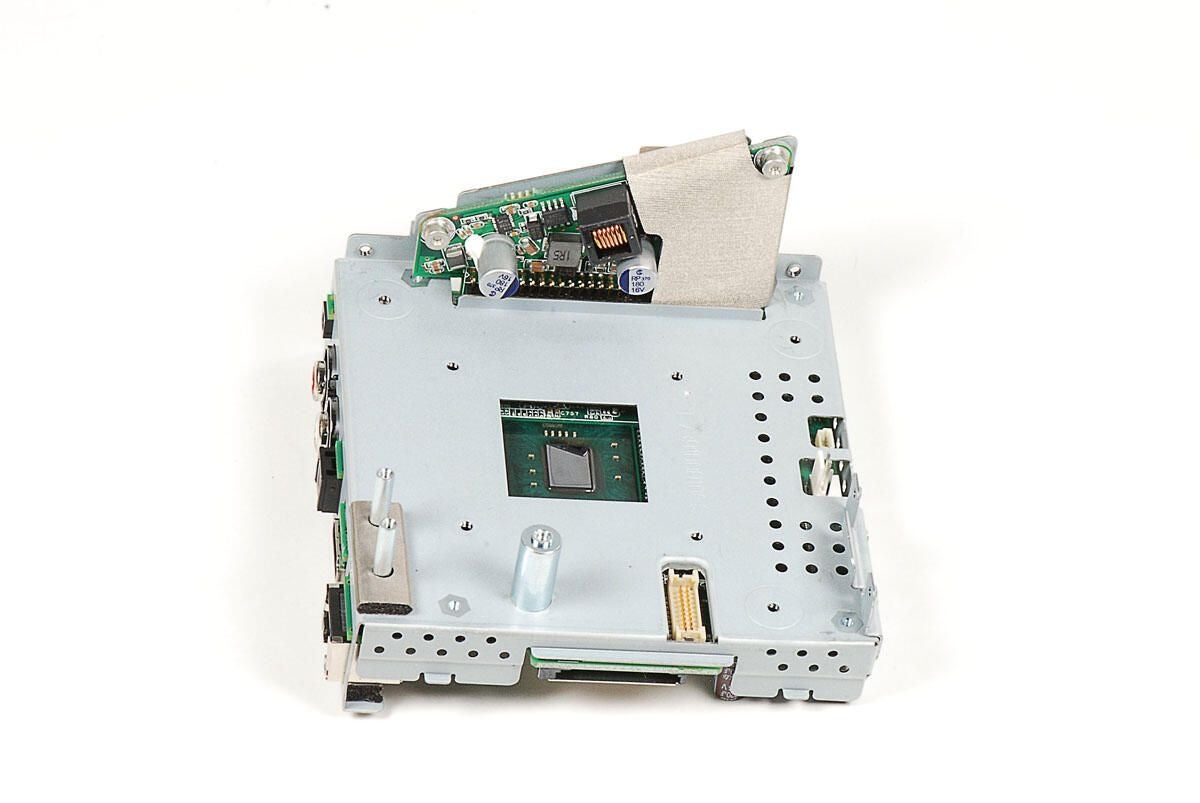
You can see the cushion taped to the top edge of the main PCB. We’ll remove this before looking at the Boxee Box’s chips.
Photo by: Bill Detwiler / TechRepublic
Caption by: Bill Detwiler
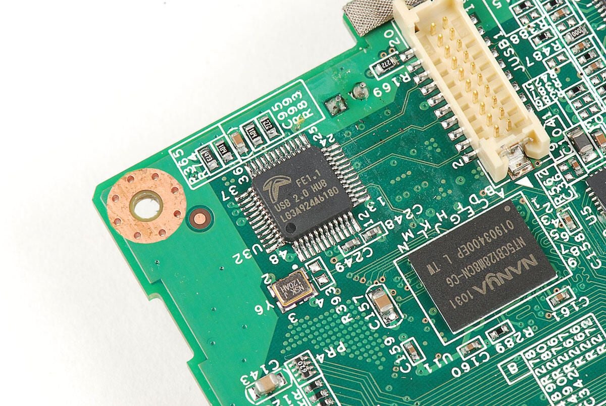
Terminus Technology FE1.1 LG3A924A6180 USB 2.0 High Speed 4-Port Hub Controller
Photo by: Bill Detwiler / TechRepublic
Caption by: Bill Detwiler
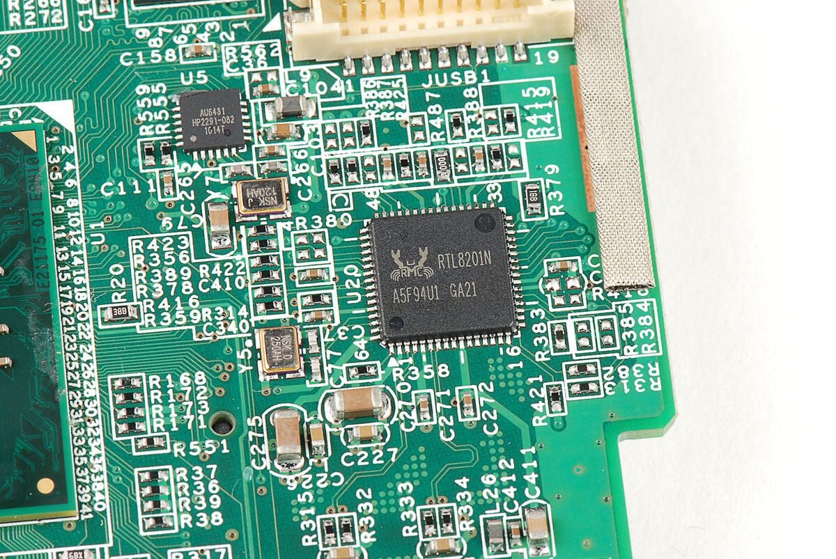
Realtek RTL8201N Single-Chip/Port 10/100M Fast Ethernet PHYceiver with Auto MDIX
Photo by: Bill Detwiler / TechRepublic
Caption by: Bill Detwiler
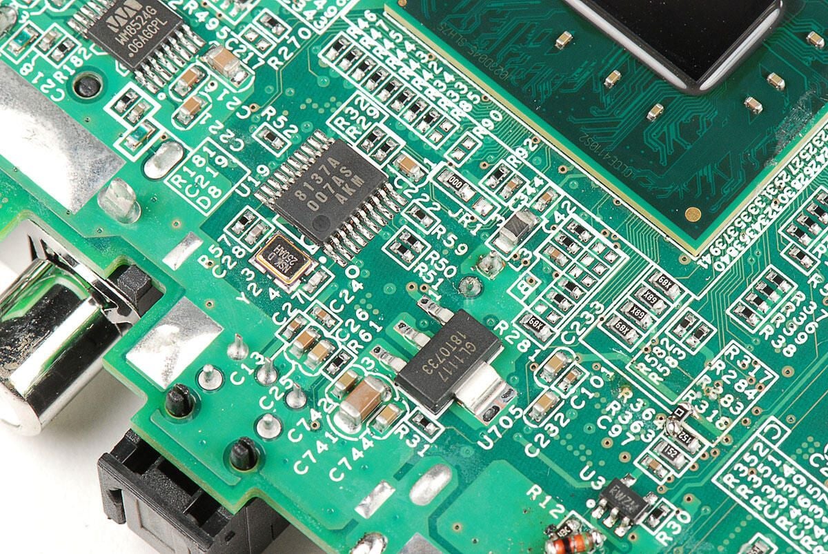
AKM AK8137A low power multi clock generator (top)?
?Gleam Micro GL1117 Linear Regulator
Photo by: Bill Detwiler / TechRepublic
Caption by: Bill Detwiler
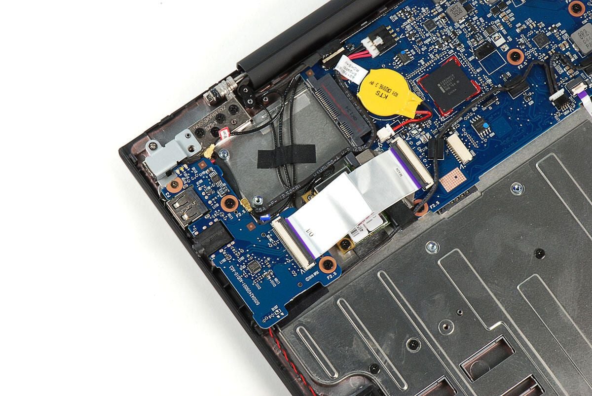
Photo by: Bill Detwiler / TechRepublic
Caption by: Bill Detwiler
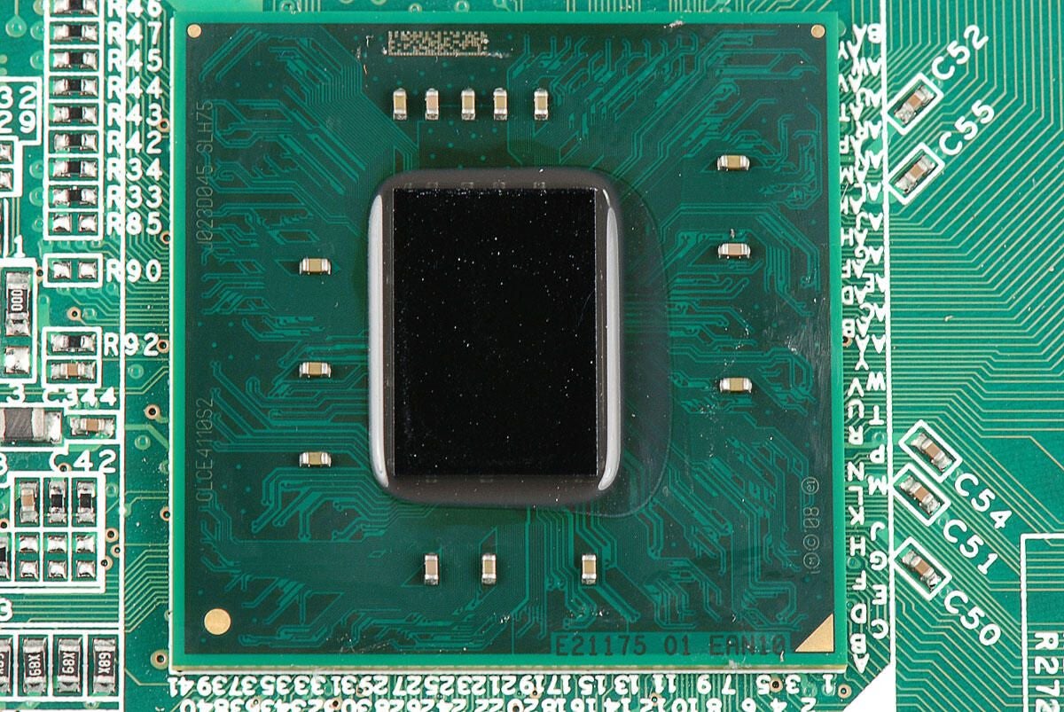
Intel Atom processor CE4110 System-on-Chip (SoC)
Photo by: Bill Detwiler / TechRepublic
Caption by: Bill Detwiler
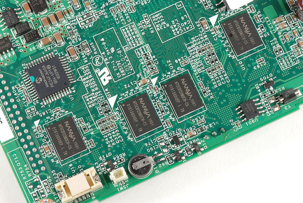
Four 1GB Nanya NT5CB128M8CN-CG DDR3 SDRAM chips sit directly under their counterparts on the top of the main PCB.
Photo by: Bill Detwiler / TechRepublic
Caption by: Bill Detwiler
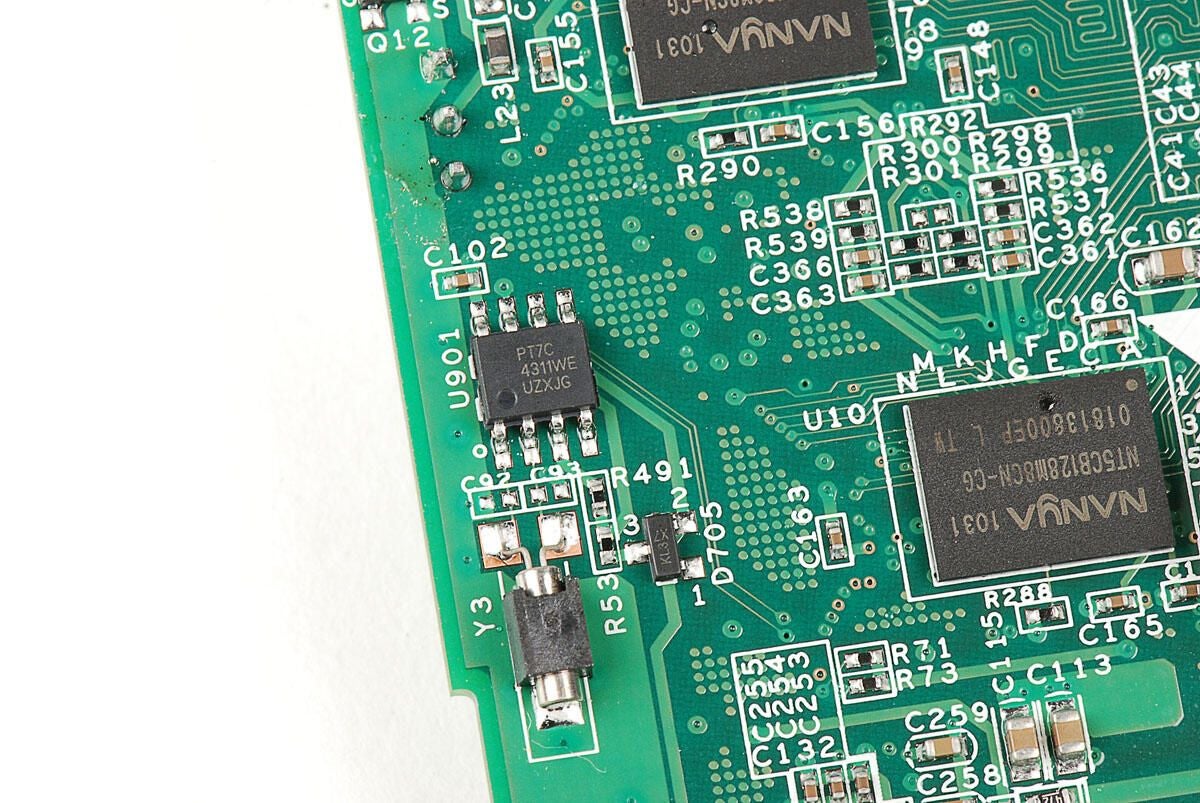
Pericom Technology PT7C4311WE Real-time Clock Module
Photo by: Bill Detwiler / TechRepublic
Caption by: Bill Detwiler
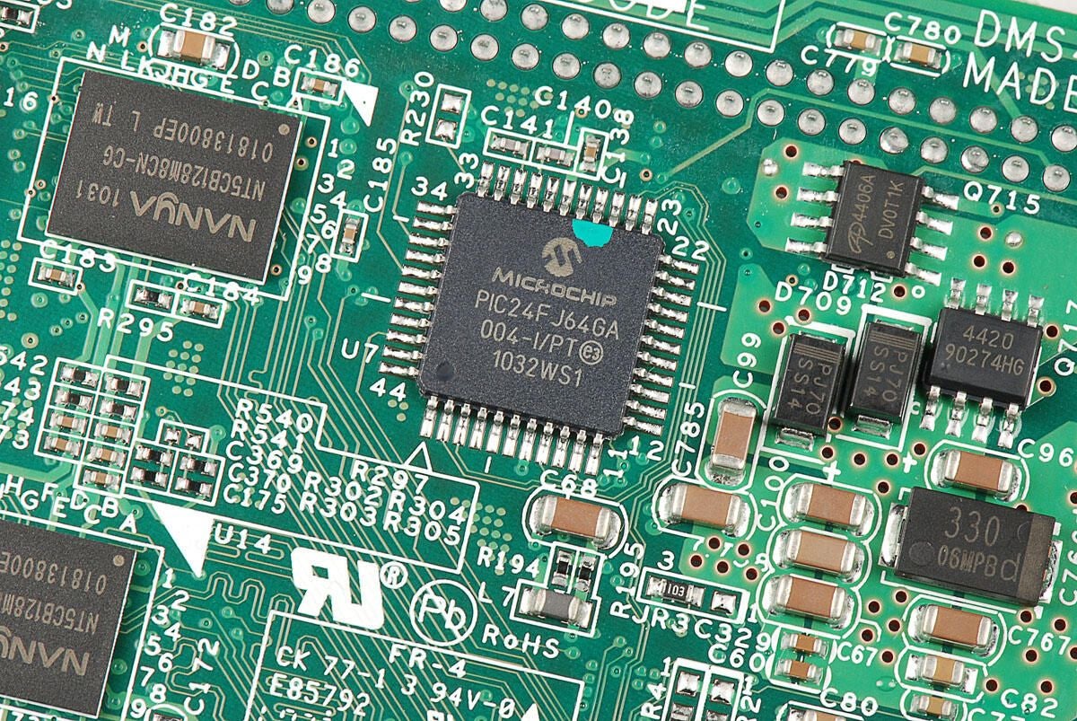
Microchip Technology PIC24FJ64GA004 16-bit microcontroller
Photo by: Bill Detwiler / TechRepublic
Caption by: Bill Detwiler
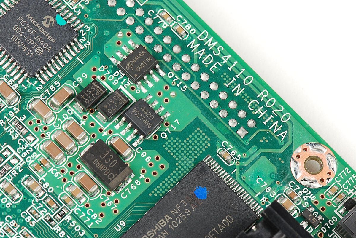
Photo by: Bill Detwiler / TechRepublic
Caption by: Bill Detwiler
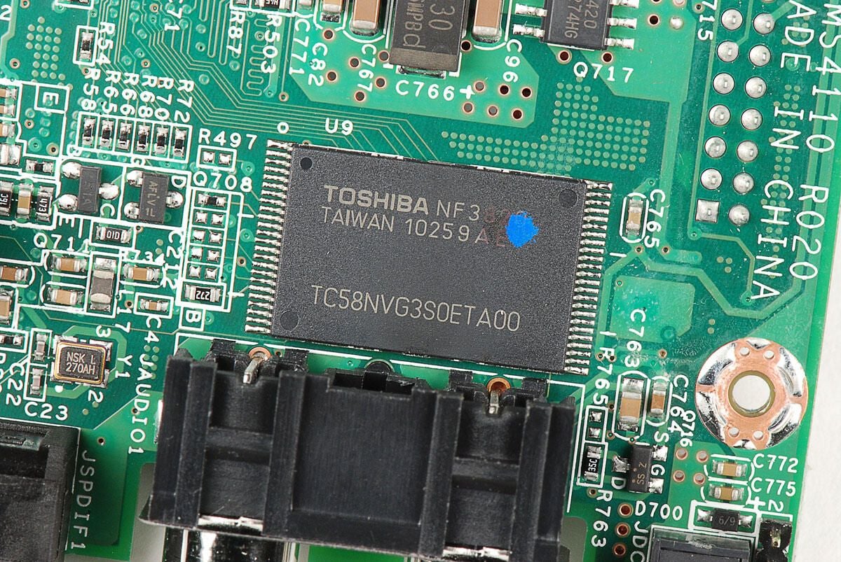
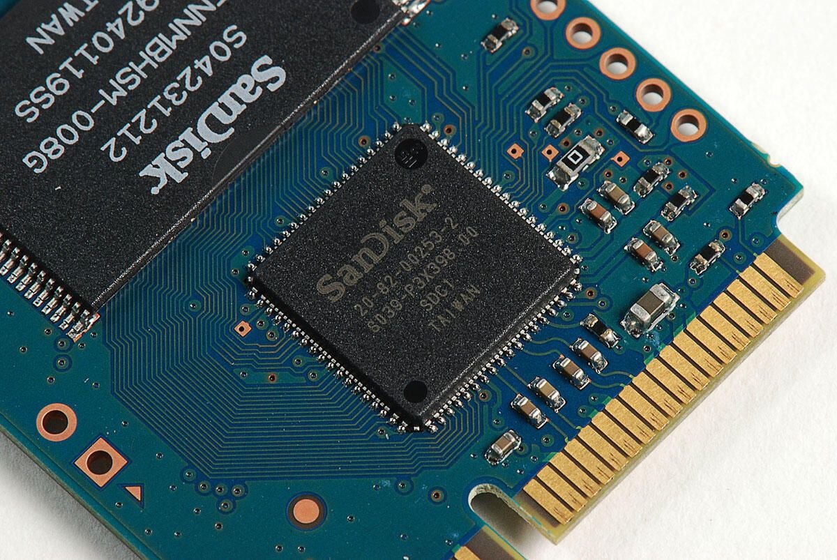
Toshiba TC58NVG3S0ETA00 NAND Flash memory chip
Photo by: Bill Detwiler / TechRepublic
Caption by: Bill Detwiler
NXP Semiconductor 4776 HDMI interface (left) and Taiwan Semiconductor TS21C (right)
Photo by: Bill Detwiler / TechRepublic
Caption by: Bill Detwiler
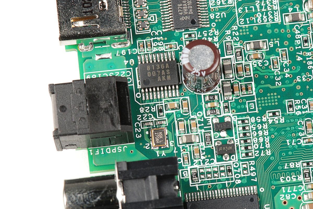
AKM AK8136A Low Power Multi-clock Generator with VCXO
Photo by: Bill Detwiler / TechRepublic
Caption by: Bill Detwiler
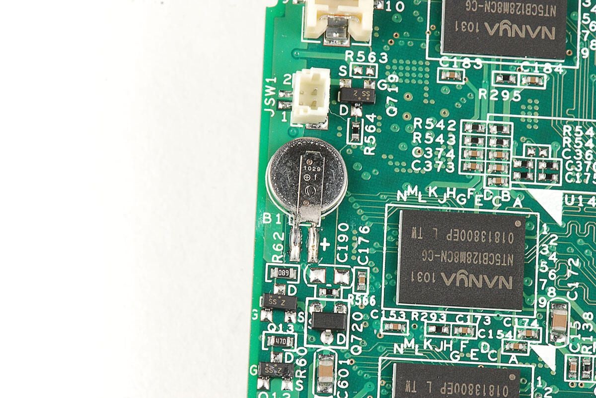
Photo by: Bill Detwiler / TechRepublic
Caption by: Bill Detwiler
Bill Detwiler is the Editor for Technical Content and Ecosystem at Celonis. He is the former Editor in Chief of TechRepublic and previous host of TechRepublic's Dynamic Developer podcast and Cracking Open, CNET and TechRepublic's popular online show. Previously, Bill was an IT manager in the social research and energy industries. He has bachelor's and master's degrees from the University of Louisville, where he has also lectured on computer crime and crime prevention.
