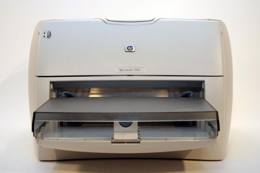
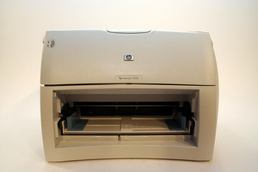
The HP LaserJet 1300 is a workhorse desktop laser jet printer. Featuring 1200 x 1200 dots-per-inch resolution, the printer shipped with 16MB of RAM (expandable to 80MB) and is capable of printing 20 pages (black) per minute.
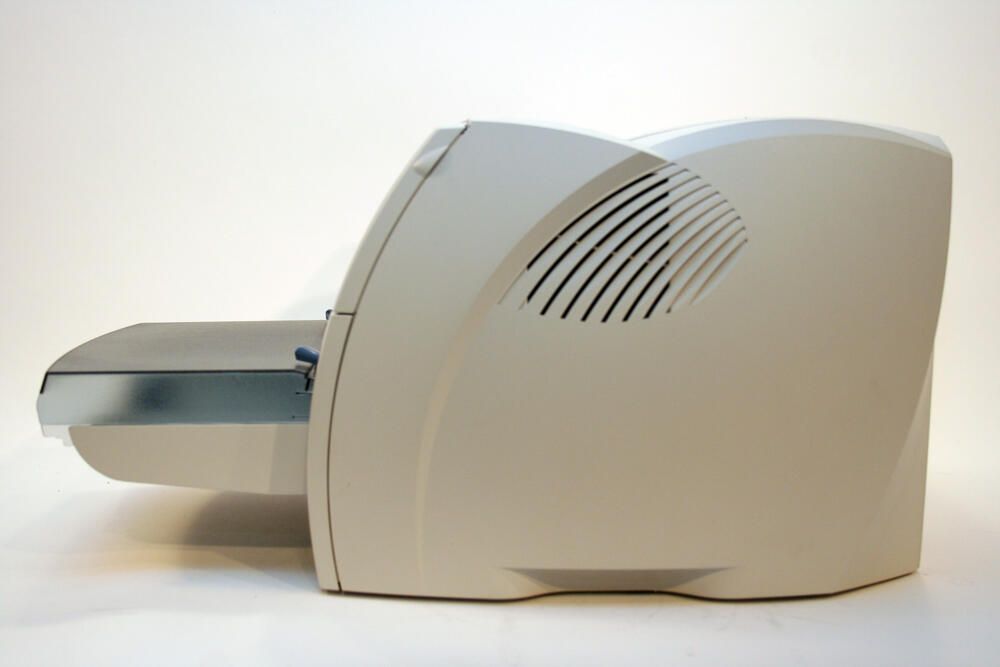
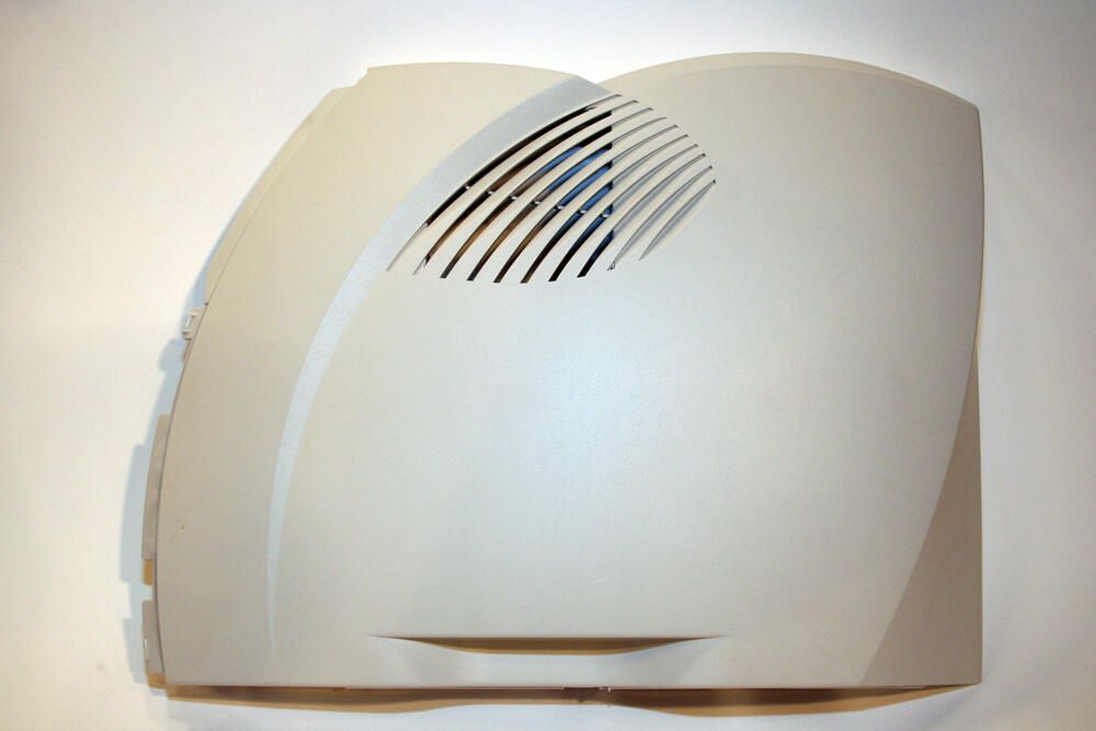
The HP LaserJet 1300 boasts clean, contoured design lines. Here, too, you can see an air vent on the unit’s right side.
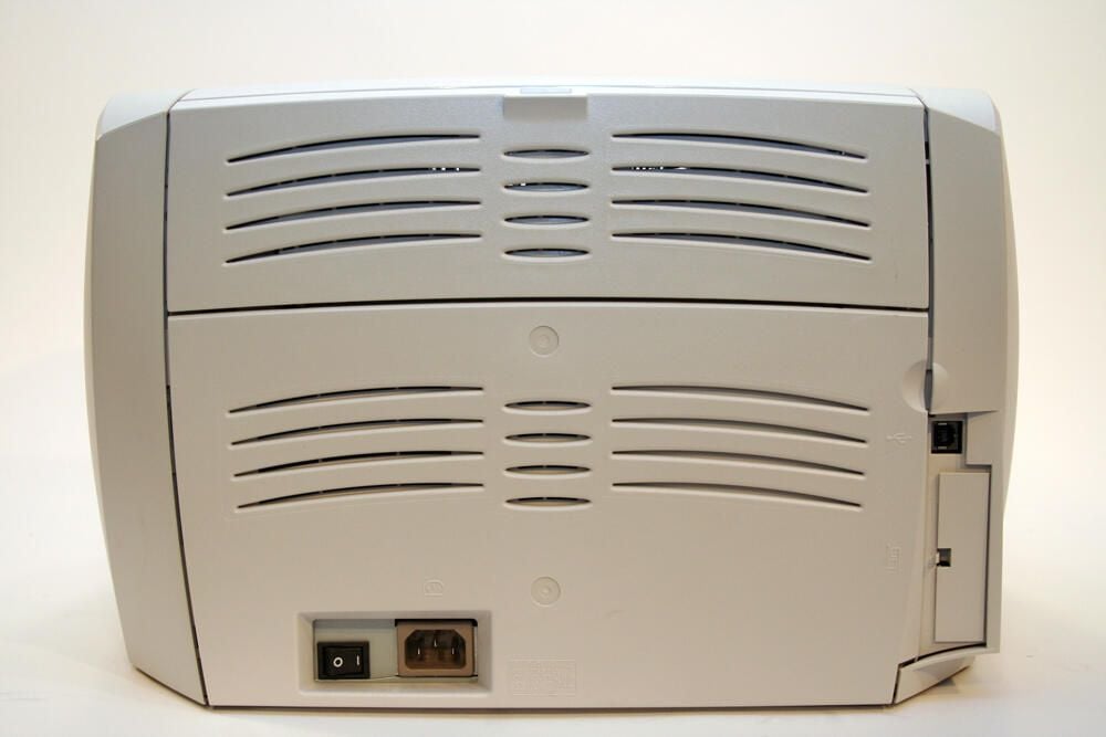
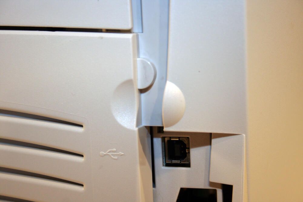
The back of the HP laser jet printer possesses few ports. At the bottom left you can see a power switch and the standard AC plug.
The HP badge, and LaserJet 1300 label, sit atop the unit’s toner cartridge door.
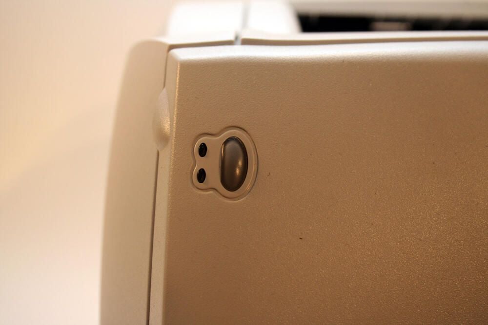
The printer’s status indicators and control panel (a single “Go” button) are very simple. The top LED is the Ready light; the bottom LED is the Attention indicator.
The oval-ish button to the right of the LEDs, meanwhile, is the Go button used for manual print jobs and to print demonstration and configuration pages.
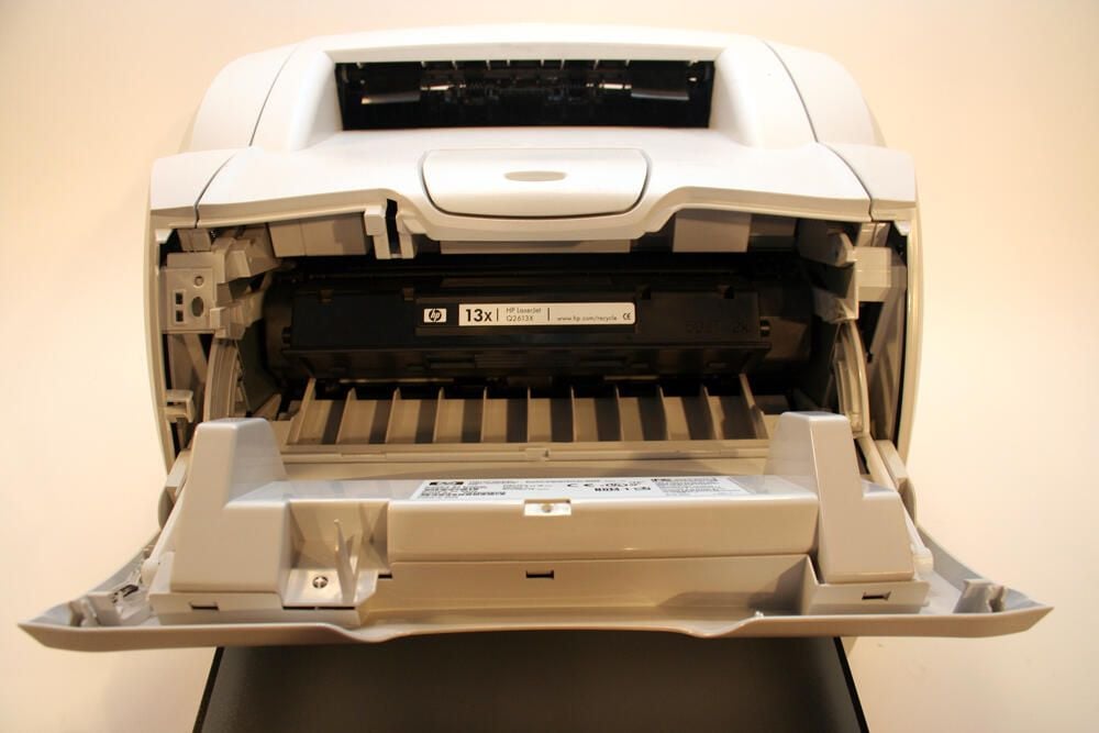
With the printer’s front cover opened, the unit’s 13x toner cartridge is visible.
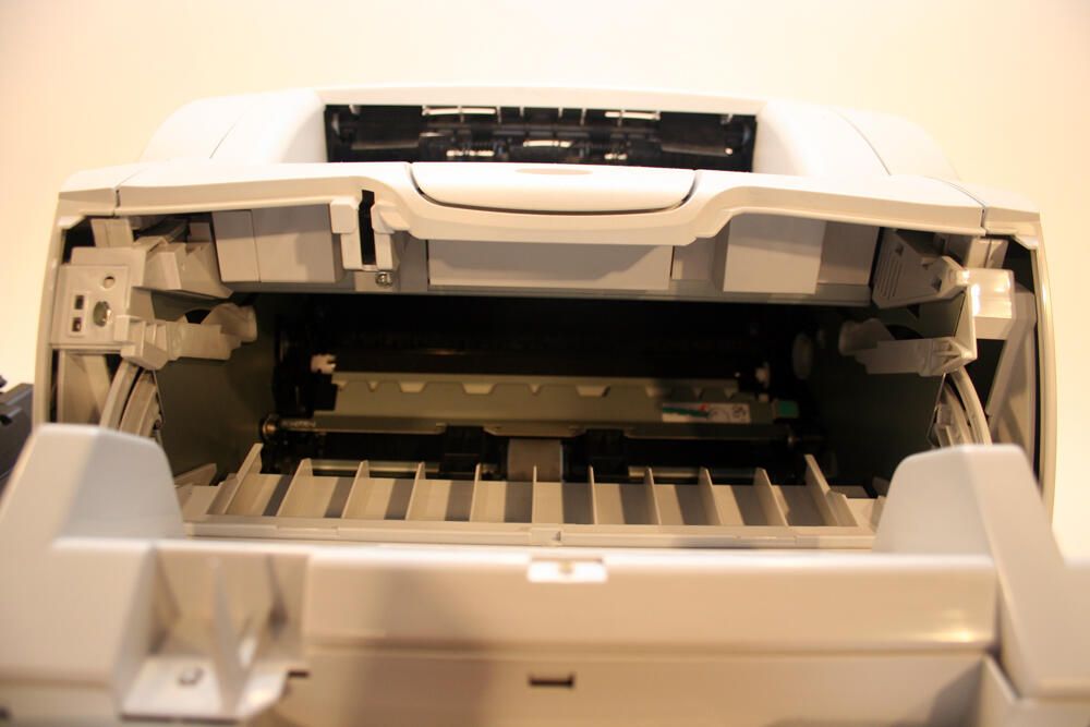
Here’s the HP LaserJet 1300 with its front cover opened and the toner cartridge removed.
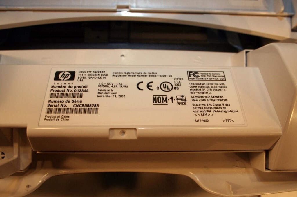
Specific model information appears on this HP label, which is affixed to the inside of the toner cartridge door. The unit’s product and serial numbers are found here.
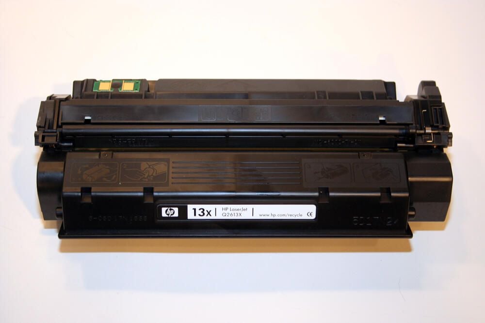
At just over two-and-a-half pounds, the 13X high-capacity toner cartridge can produce 4,000 pages (when print density is set to 3 and the printer’s EconoMode is set to Off).
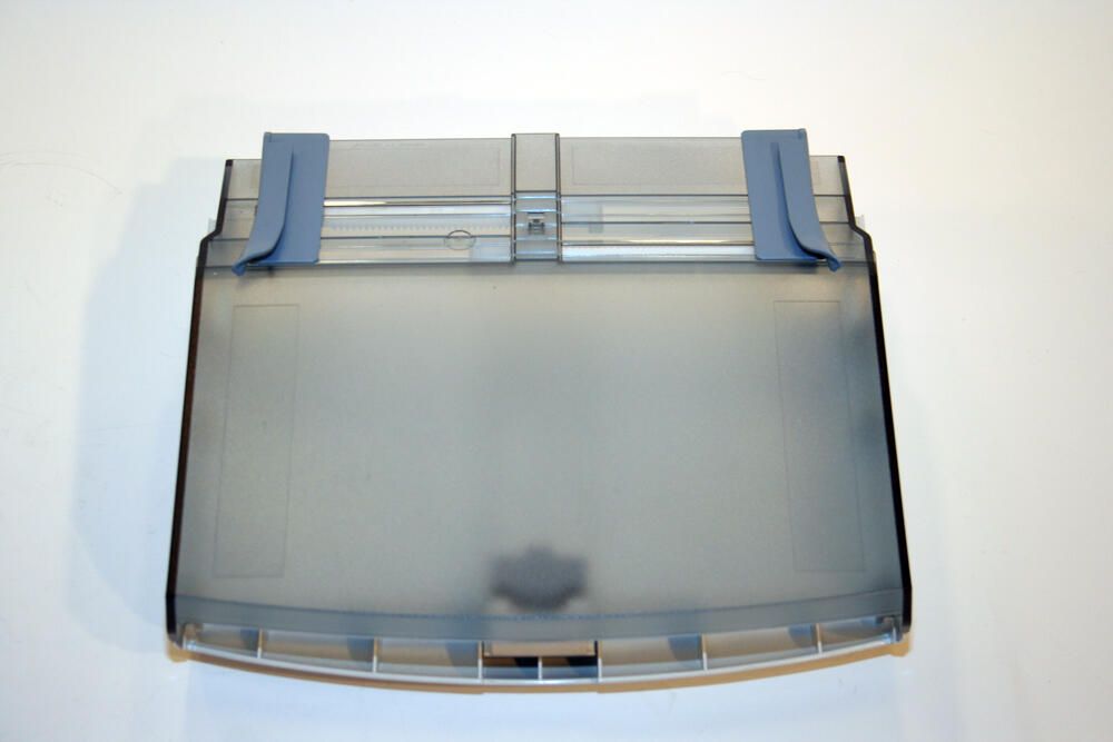
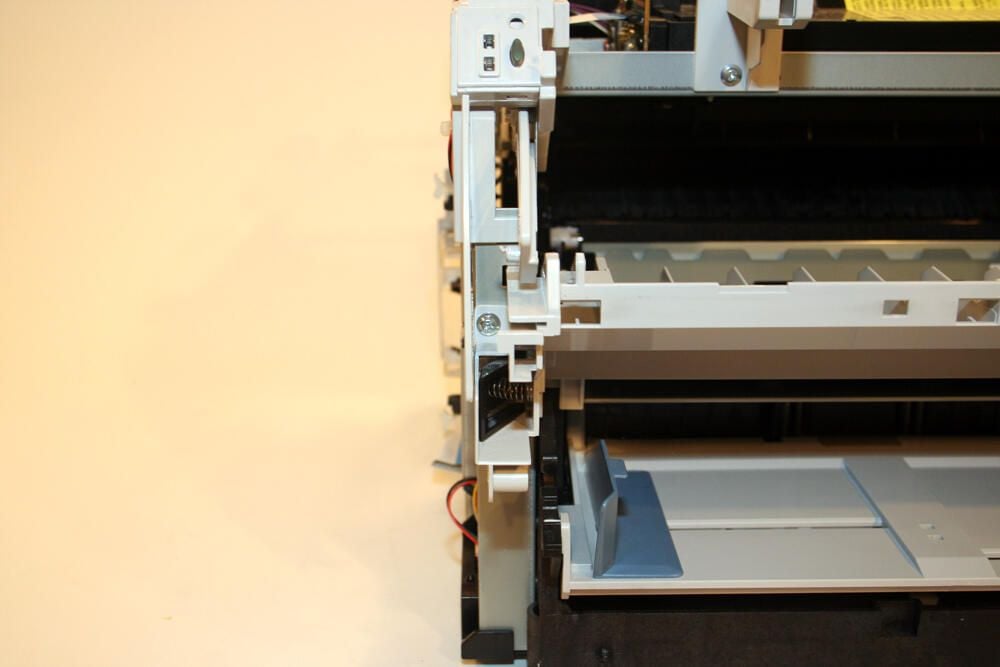
Here is the paper input tray (with the corresponding top cover in place), once removed from the laser jet printer.
To remove the left-side cover assembly, HP designed a groove (shown here) into the case. By pulling with one’s thumb on this notch, the left-side assembly cover can be removed.
Users needed to remove this cover in the event they wished to add additional memory to the printer.
Here’s a look at the HP LaserJet 1300’s left side with that side’s cover assembly removed. The additional RAM slot can be seen in the image’s bottom-left quadrant.
The single DIMM memory slot holds either an 8-, 16-, 32- or 64-MB RAM chip.
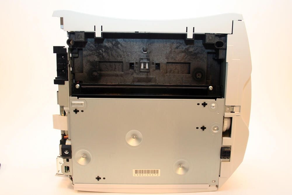
Here’s a look at the bottom of the HP LaserJet 1300 printer (with the left-side cover assembly removed).
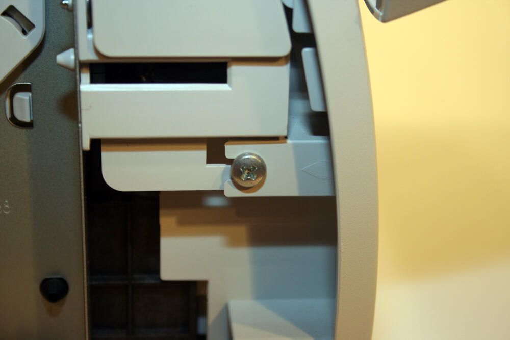
To remove the HP’s lower front cover, Philips head screws (such as this one revealed by the removal of the left-side cover assembly) must be removed.
Here’s how the 1300 printer appears with the lower front cover and paper input tray removed.
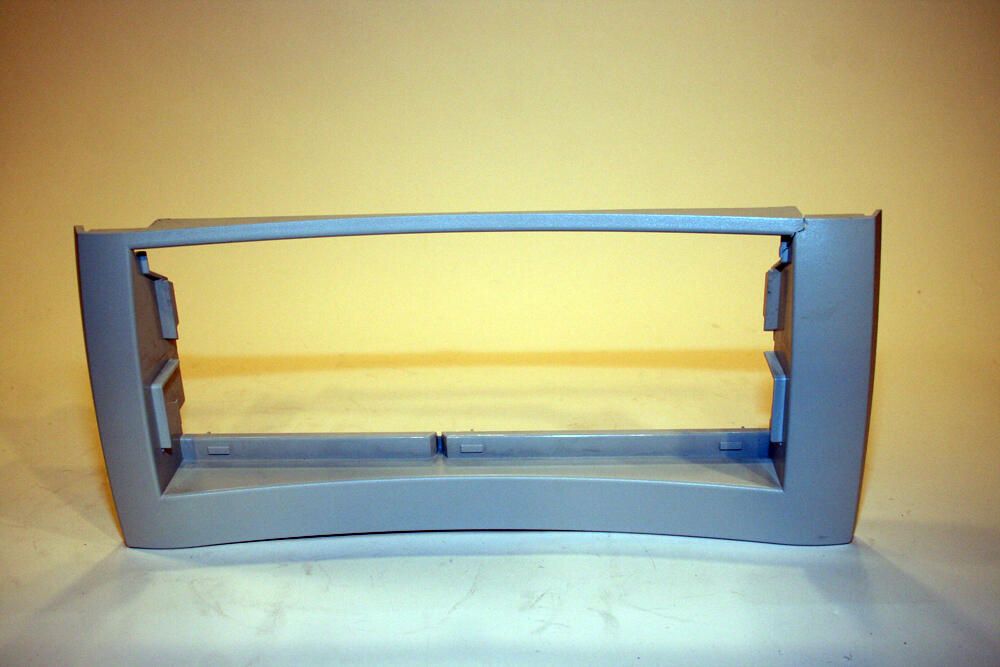
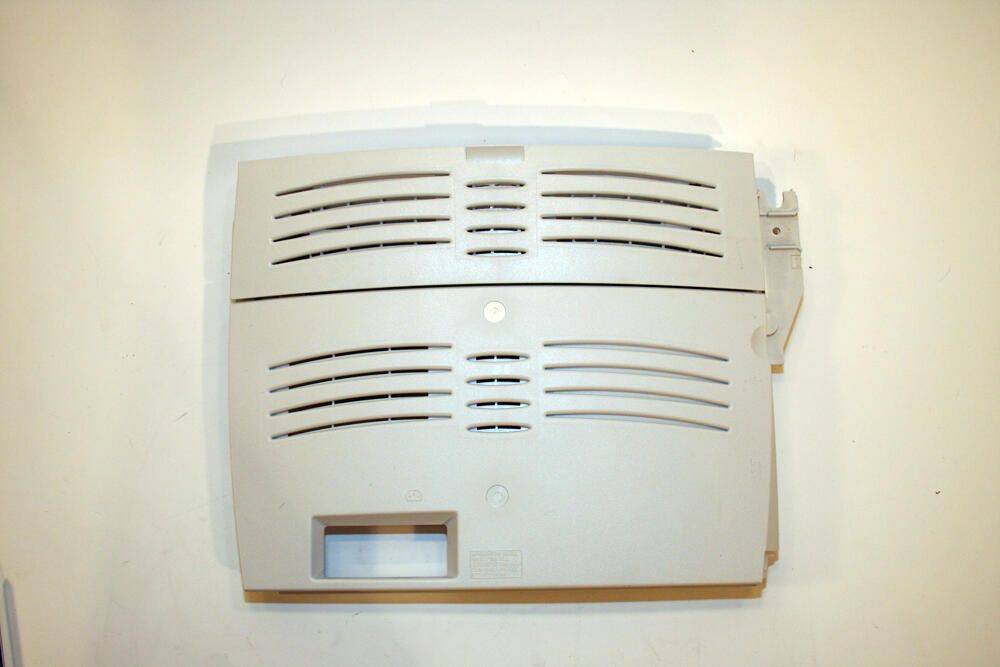
Here’s the lower front cover, once removed from the HP printer.
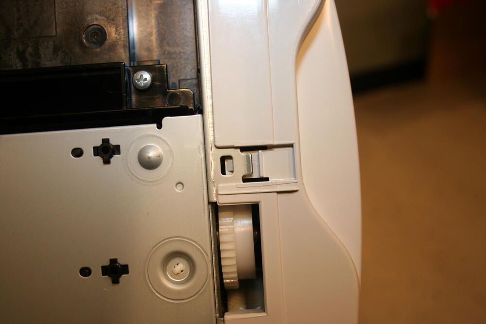
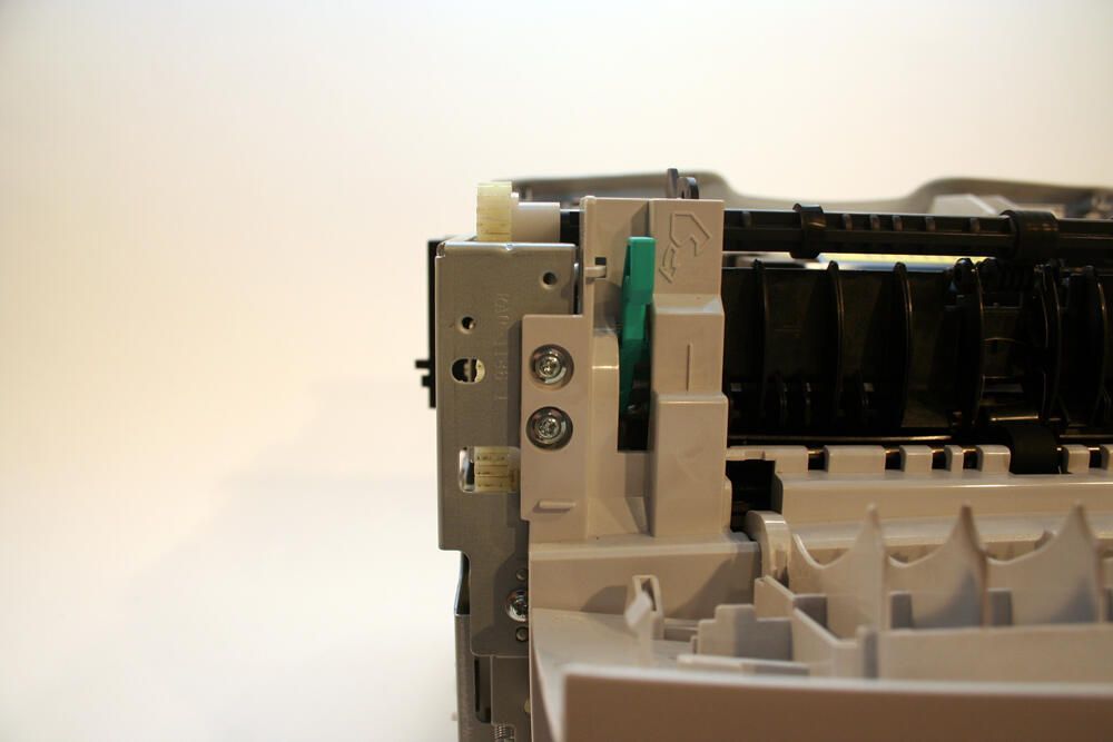
To remove the right cover assembly, the tab shown in this image must be depressed. I used a simple small screwdriver to depress this tab and help separate the two components.
With the tab depressed, you can separate the right-side cover assembly by moving it away from the main printer body.
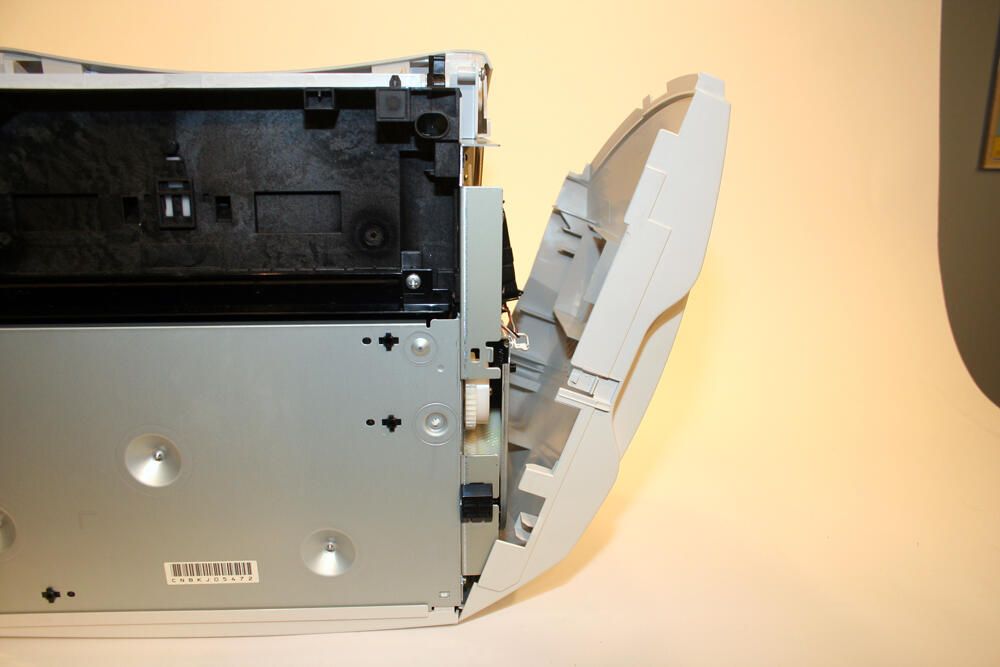
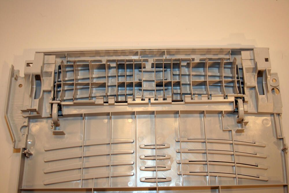
Here’s the right cover assembly, as it appears after removing it from the main printer body.
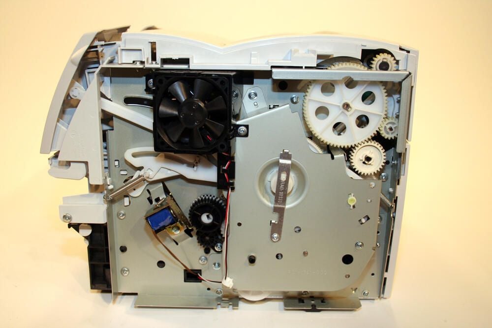
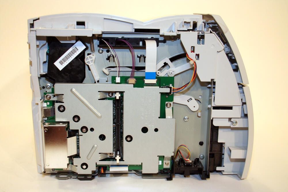
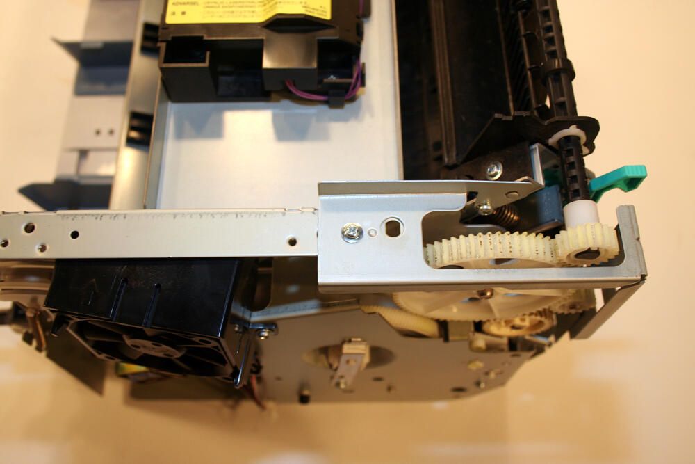
Here’s a look inside the HP 1300 with the right cover assembly removed.
To the top left you can clearly see the black cooling fan.
To the top right is the large 69-tooth gear that’s part of the right-side plate assembly. Ultimately, these gears work to guide paper through the paper pick-up and fusing mechanisms.
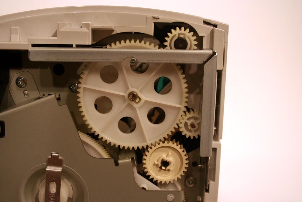
In this image you can see the many gears that drive the unit’s fuser (fixer) assembly.
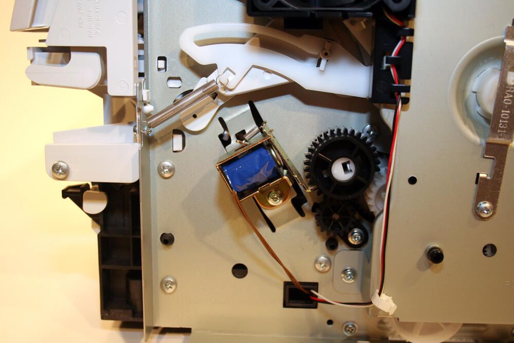
Other items found on the right plate assembly include the tension spring (seen here toward top-left-center), assorted gears that help drive the paper pick-up assembly and the blue solenoid that engages the paper pick-up roller gear and corresponding clutch assembly.
With the Philips head screws removed, the printer’s top cover can be pulled free of the unit.
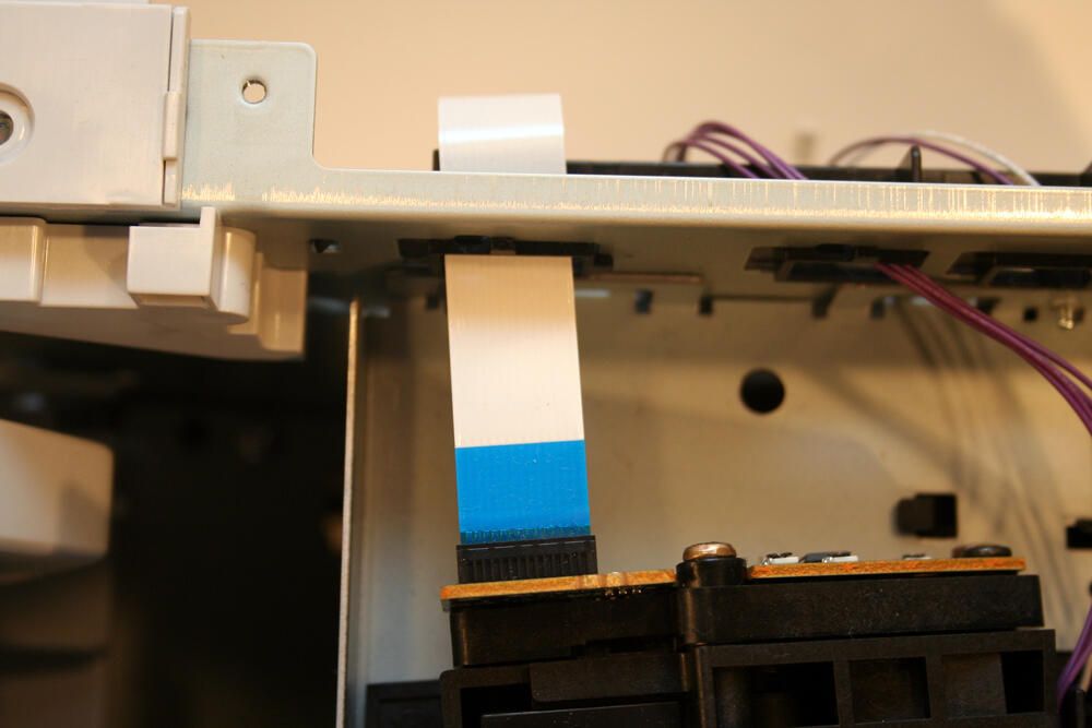
Here’s a close up view of the data ribbon cable that enables communication between the printer’s electronic brains and the laser/scanner assembly.
Dozens of Philips head screws must be removed to disassemble the LaserJet 1300. Here two more can be seen behind the open rear cover.
With additional Philips head screws removed, the unit’s Rear Cover separates from the main printer body.
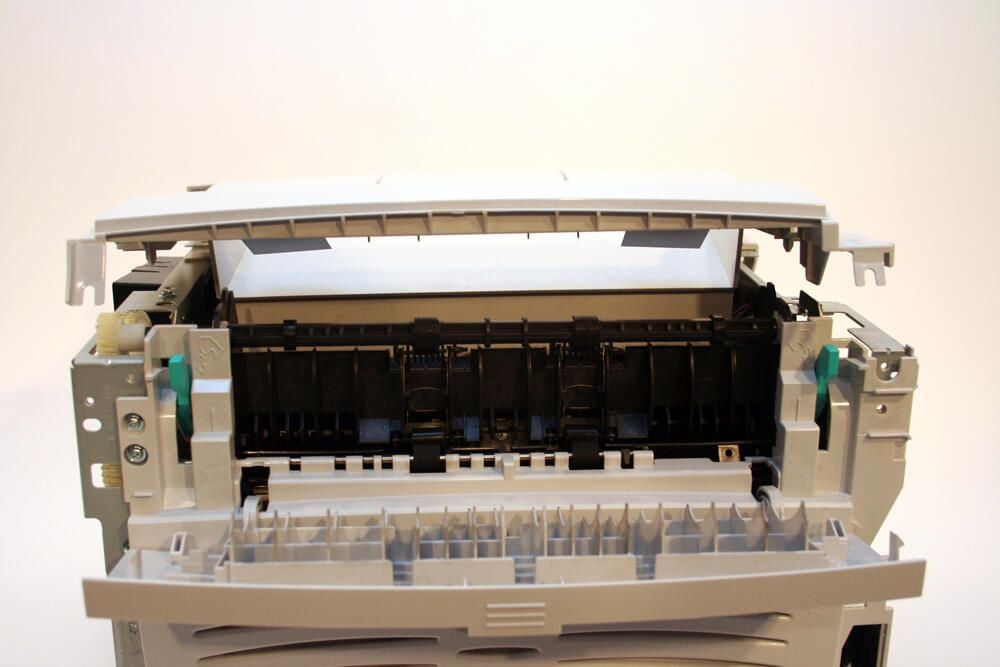
Note the back cover assembly’s top third is composed of a hinged door (here pictured closed) that serves as the unit’s straight-through output door.
With the back cover laid on its back (here you’re viewing the internal side typically secured to the main printer body), the hinged straight-through output door is more readily identifiable.
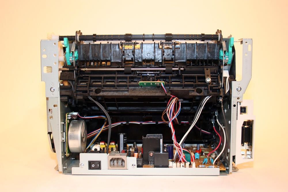
With the printer’s rear cover removed, the unit’s motor assembly (bottom left), DC Controller board (bottom) and the paper pick-up assembly’s black backside are visible.
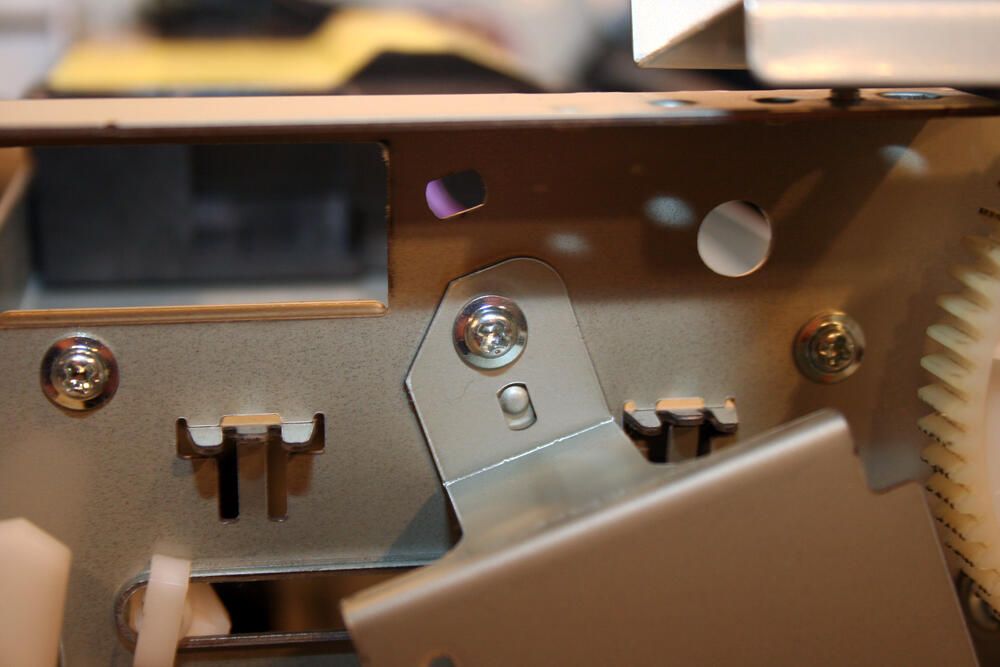
Removing components of the paper guide assembly requires the removal of several more Philips head screws, as shown here.
Note that, at the top center of the image, you can make out the status LEDs and Go button.
Removing the right- and left-side plate assemblies also requires additional Philips head screws be removed.
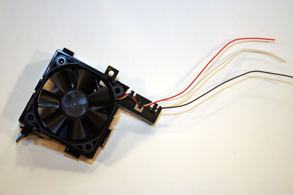
Here’s the printer’s cooling fan, once it’s been removed from the right-side plate assembly.
Disassembling the right-side plate requires the removal of numerous additional Philips head screws. In all, several dozen of these fasteners had to be removed to disassemble the unit and its guides, boards, covers and other components.
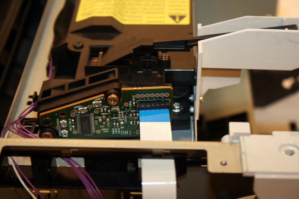
This printed circuit board feeds the HP’s laser/scanner assembly’s operation.
Pictured here is the data ribbon cable (and power connector) that connect the HP’s laser/scanner assembly to the unit’s formatter assembly board. Officially, the formatter assembly board receives HP part number Q1890-60001.
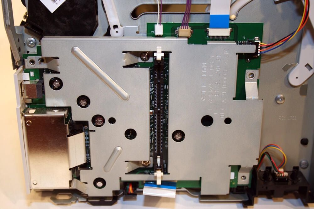
The formatter assembly (with its available extra RAM slot) is hidden behind this metal cover.
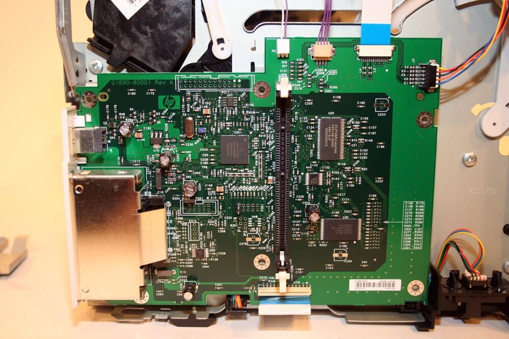
With several Philips head screws removed, the metal cover falls away revealing the HP-manufactured formatter assembly board.
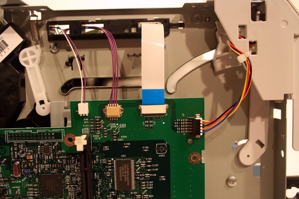
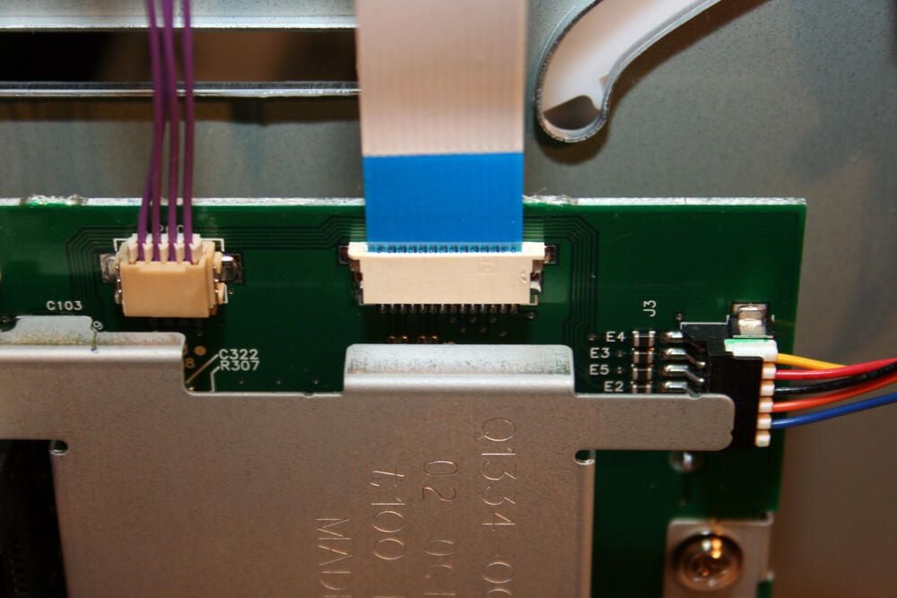
Here’s another look at the formatter assembly’s electronic connections (including the data ribbon cable that links with the laser/scanner assembly).
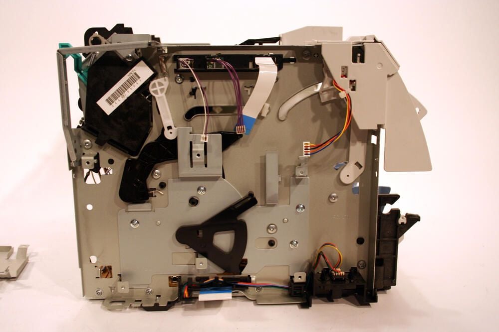
Pictured here is the left plate assembly, minus the formatter board.
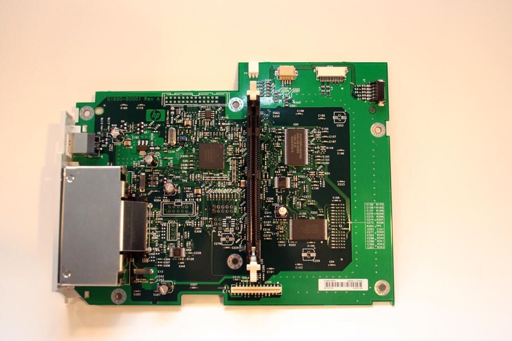
Here’s a closer look at the formatter assembly by itself. The straight black vertical bay accepts an additional DIMM memory chip, while the rectangular silver metal housing to the bottom left accommodates the model’s LIO connection.
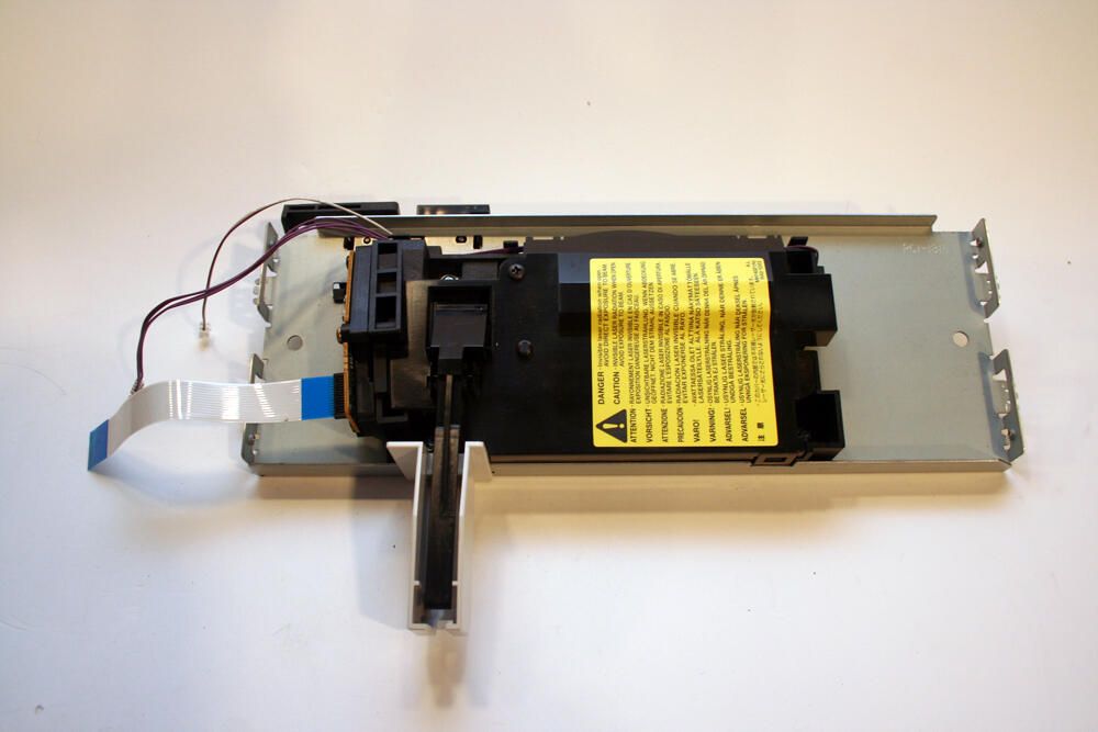
The laser/scanner assembly is pictured here by itself. At $80 to $160 or more on the used parts market, this is likely the printer’s most expensive component.
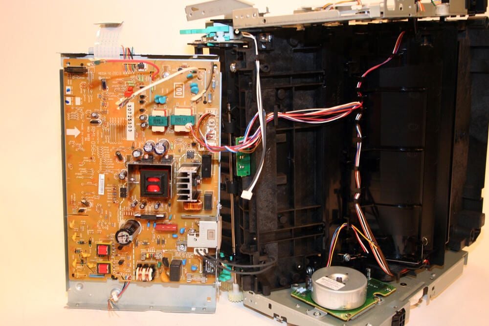
With the screws removed that secure the DC controller pan support to the main printer unit, the DC controller itself is clearly visible.
This control board (the orange-beige printed circuit board to the left) carries model number RM1-0564. Manufactured in China, this component serves as the power supply and control board for the printer.
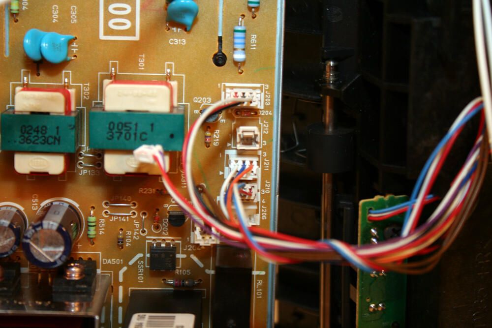
Here’s a closer look at several of the cables that connect the DC controller board and help power various printer components.
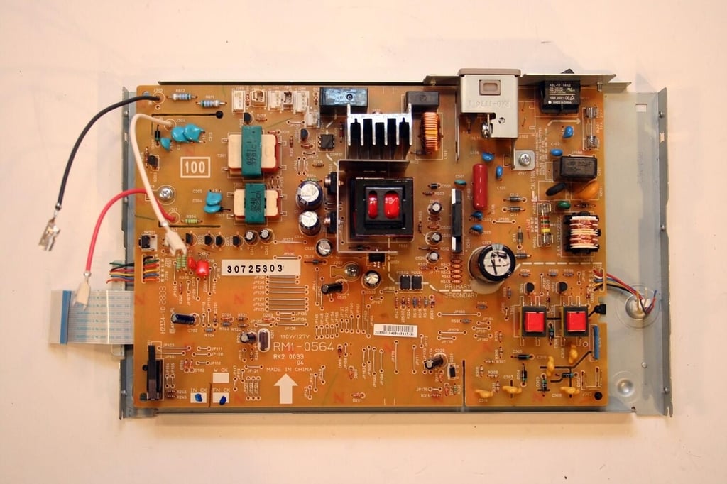
Here’s the DC controller board by itself. Note that the DC controller board still sits inside its support pan (part number RC1-1813).
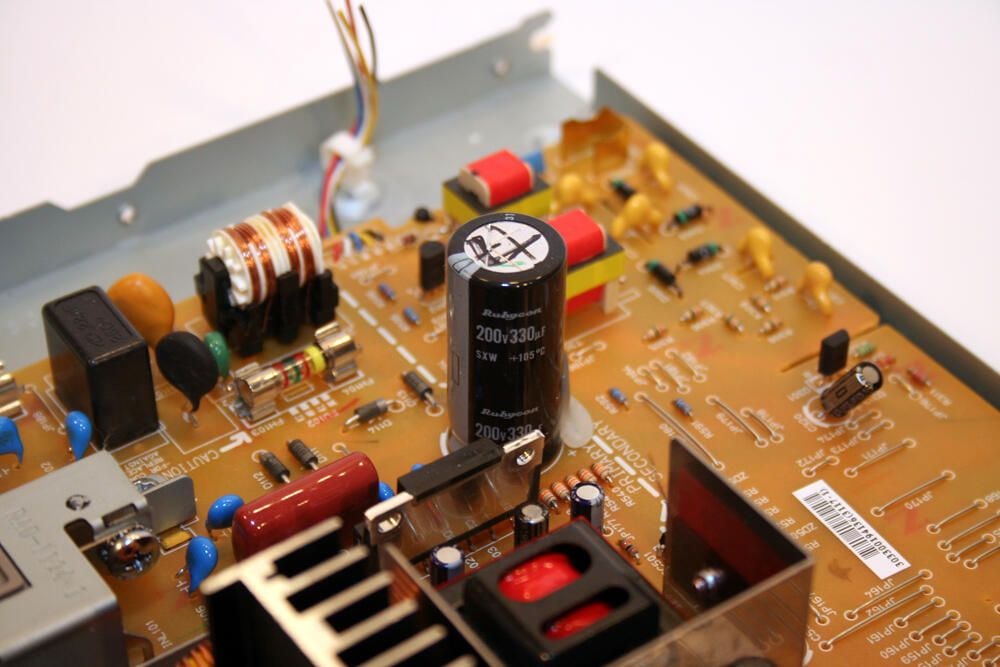
Particularly prominent on the HP LaserJet’s DC controller board is this 200v Rubycon capacitor.
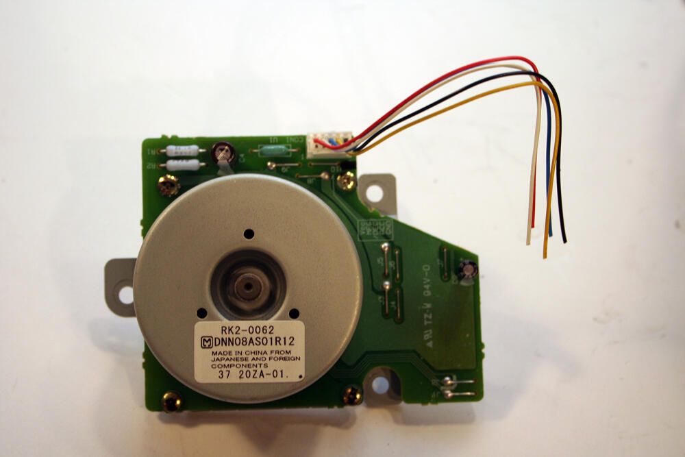
Here’s the DC stepper motor HP installed in its LaserJet 1300 series printers. The unit’s electronic board possesses its own (albeit small) capacitor (the black-ringed silver cap toward top center).
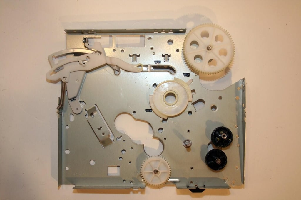
Here’s the right plate assembly, with just a few gears and a lone tension spring remaining.
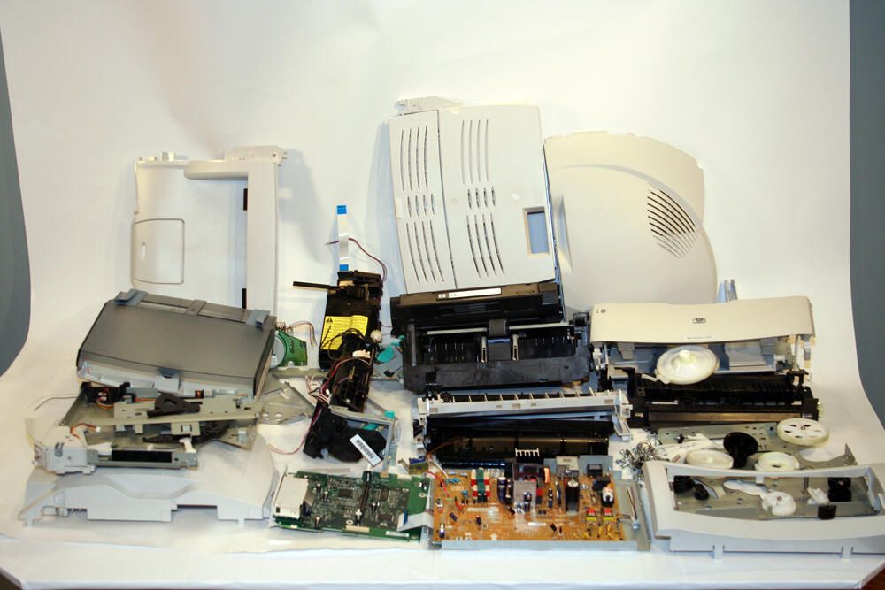
So many components compose the HP LaserJet 1300 that I could not neatly fit them all in the picture. That said, I was able to stack all the various boards, covers, guides and assemblies on this table to create this disassembled image.

Erik Eckel is a managing partner at Louisville Geek and president of Eckel Media Corp. He previously served as Executive Editor at TechRepublic. He received Microsoft Engineer accreditation from Sullivan University and earned his Bachelor's Degree in English from the University of Louisville. He's earned Network+, Windows NT 4.0 MCP+I and MCSE, and Windows 2000 Professional MCP accreditations.


