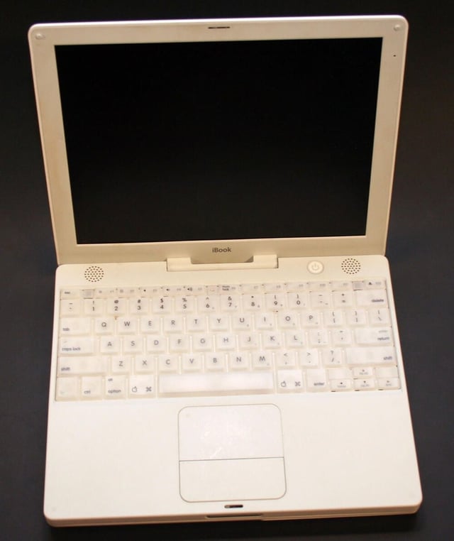
Apple’s second generation G3 iBook was first released in May 2001. The 12.1-inch active-matrix TFT display boasted a 1024×768 maximum resolution. Other specifications for the first second-generation G3 iBooks included a 500MHz CPU with 256KB L2 cache, an 8MB ATI Rage Mobility chip, a 10GB hard disk and two USB, one FireWire, one video out, an Ethernet and modem ports.
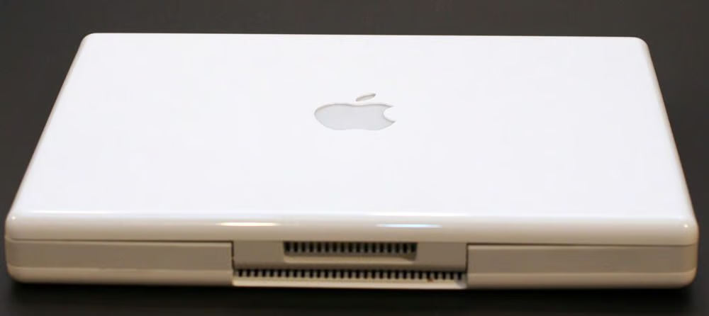
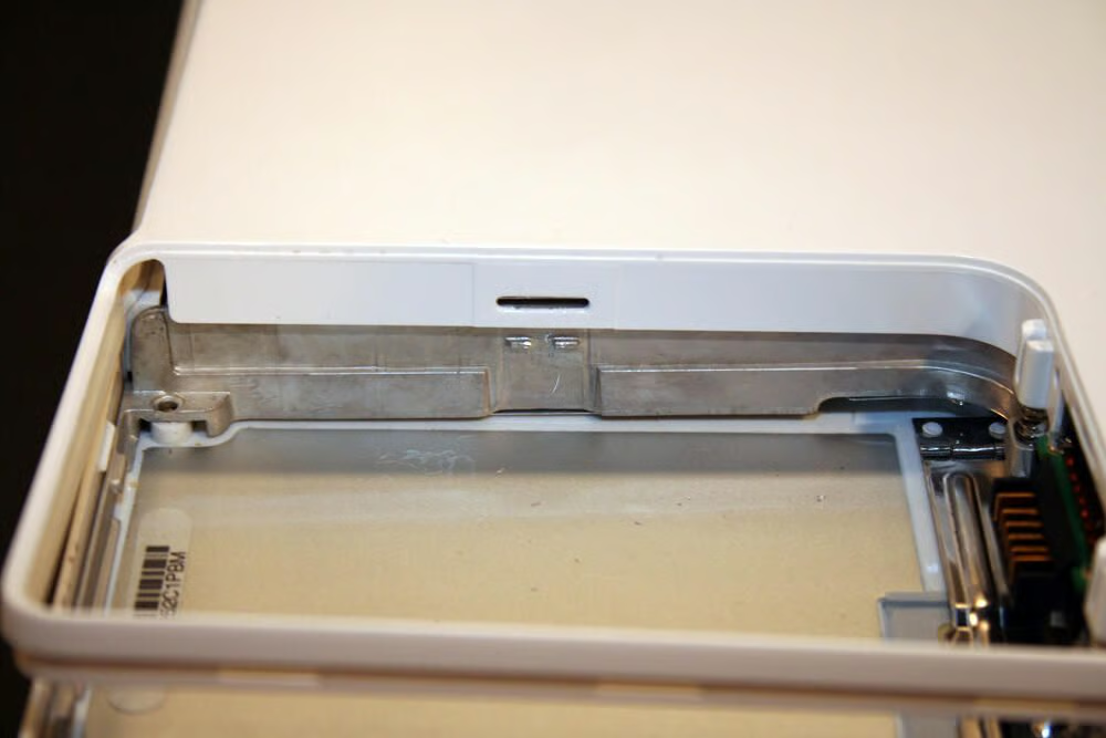
The air vents in the middle of the rear panel play a crucial role in exhausting heat from this system. As we’ll see later in this gallery, behind the white plastic vent housing is the actual metallic heat sink designed to help cool the laptop.
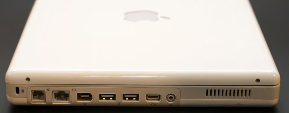
The iBook’s left side holds the unit’s (from left to right) modem and Ethernet ports, FireWire and USB ports and video out and headphone jacks.
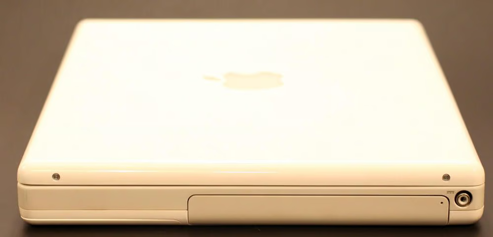
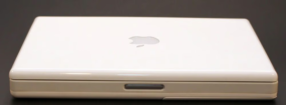
The iBook’s right side holds the laptop’s CD-RW/DVD-ROM drive and power port.
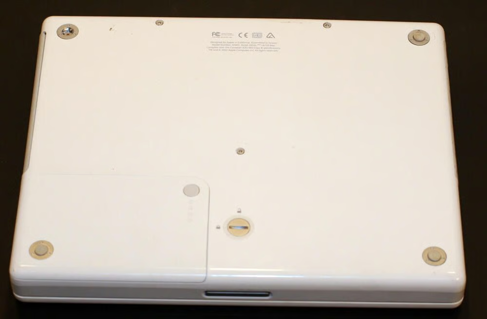
Apple’s simple designs preclude easy access to the iBook’s hard disk or even memory. Only the battery (bottom left corner) is easily replaced.
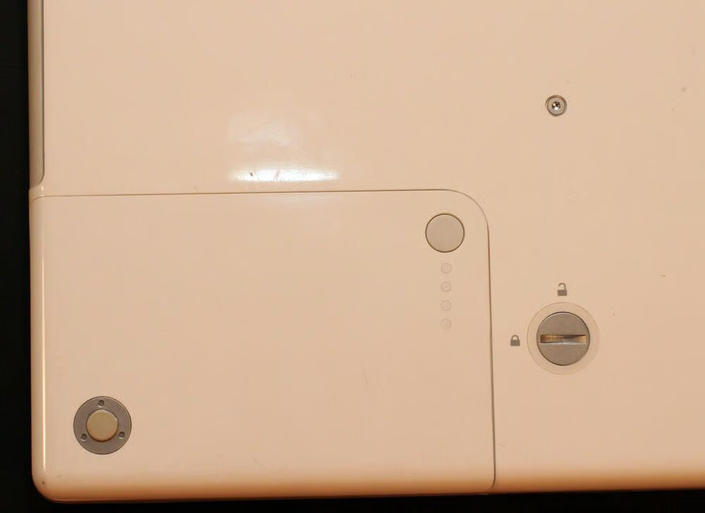
Here’s a closer look at the G3 battery compartment (with the battery in place). These models featured a simple test mechanism, whereby the circular button at the top right corner could be depressed to illuminate a series of LEDs indicating the battery’s strength.
Rubberized foot pads, which help keep the laptop from slipping when placed on desks and other flat surfaces, hide Philips head screws that must be removed to disassemble the unit. Here you can also see one of the many numerous Torx and Philips head screws that help secure iBook components.
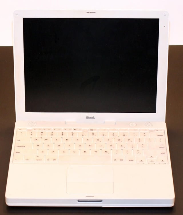
The second-generation G3 iBooks featured translucent keys and white plastic polycarbonate shells.
Stereo speakers were placed at the top right and left corners of the laptop’s bottom shell (visible here above the keyboard).
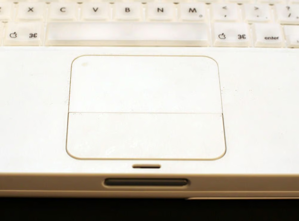
Here’s a closer look at the 2G G3 iBook Trackpad.
Apple chose a new hinge design for its non-clamshell Macs.
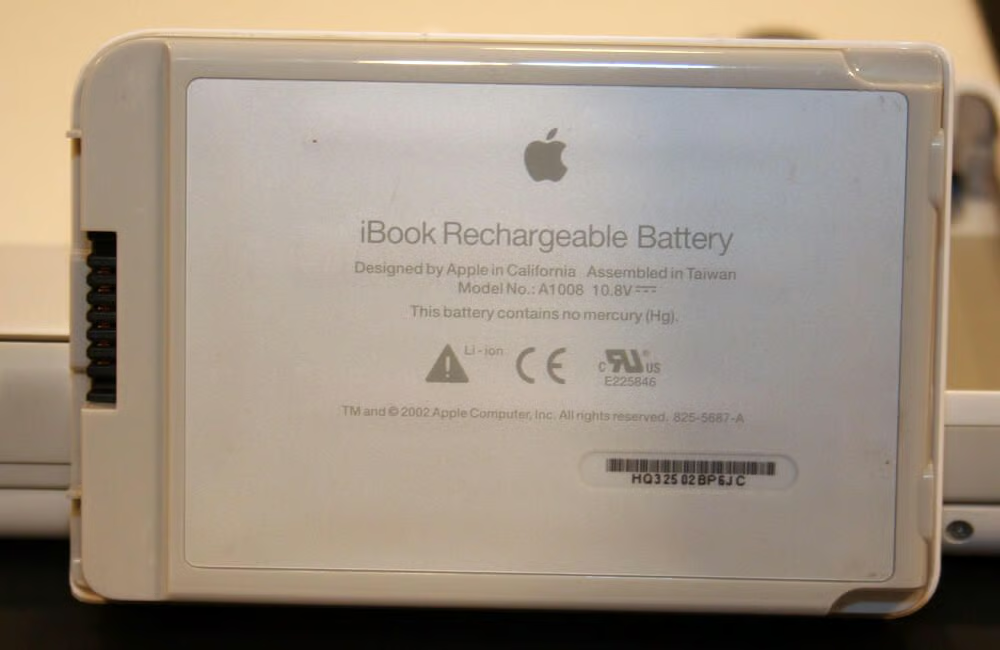
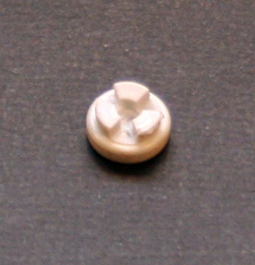
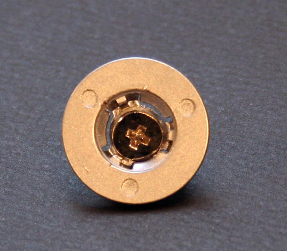
The Mac iBook’s battery itself is easily removed. Simply use a quarter to turn the silver battery release button found on the Mac’s bottom. The battery then slips away.\n\nThe actual battery, model number A1008, is a Lithium-Ion unit.
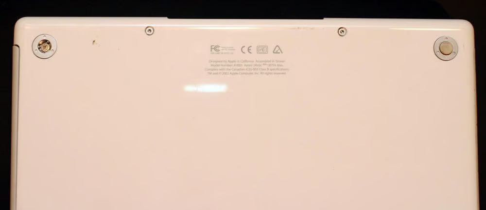
This is one of the iBook’s four rubber foot pads. Each pad hides a Philips head screw that must be removed to enable disassembly.
These metal retaining rings, of which there are three on the second-generation G3 iBook, help secure the bottom shell to the rest of the assembly.
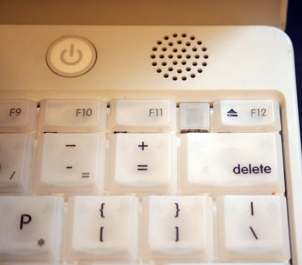
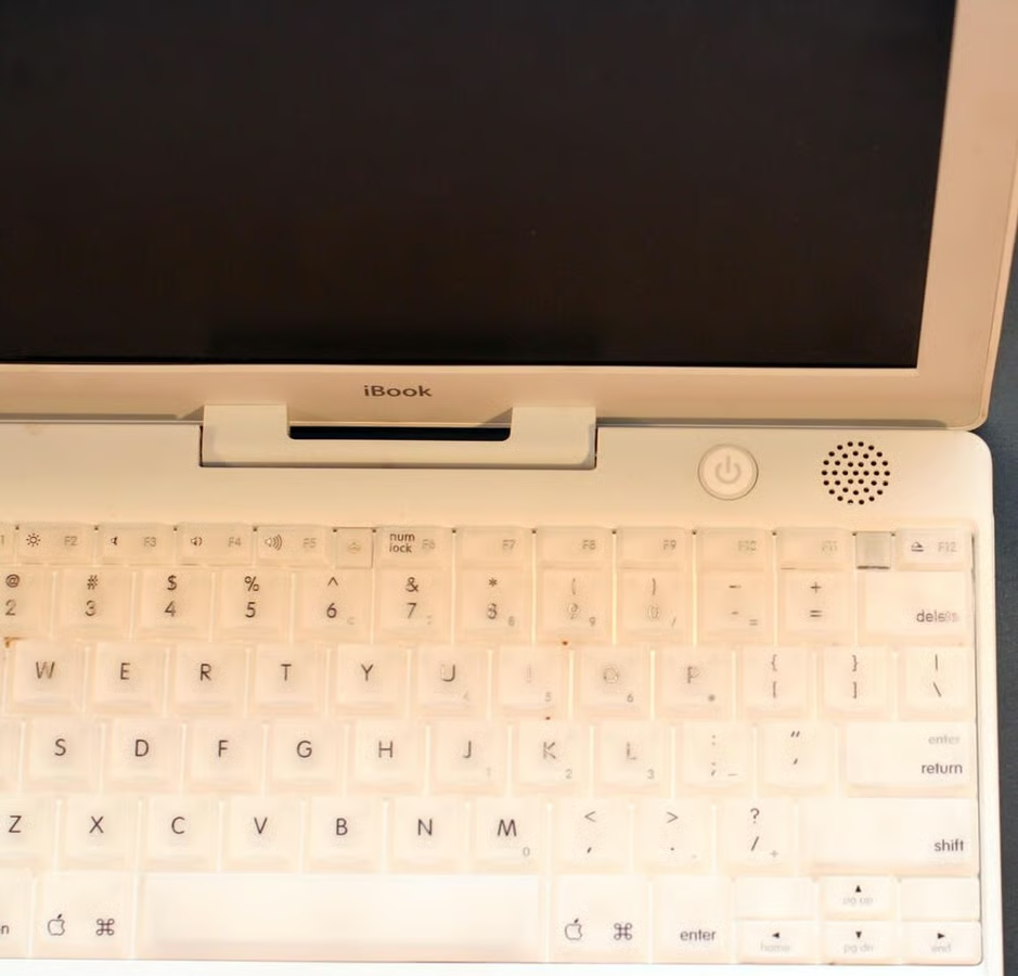
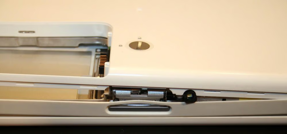
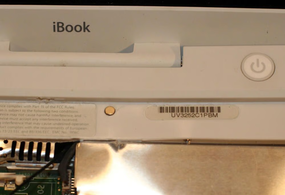
Here’s a closer look at the translucent keys, power button and one of the unit’s stereo speakers. Also important in this image is the keyboard retaining tab, which sits between the F11 and F12 keys.
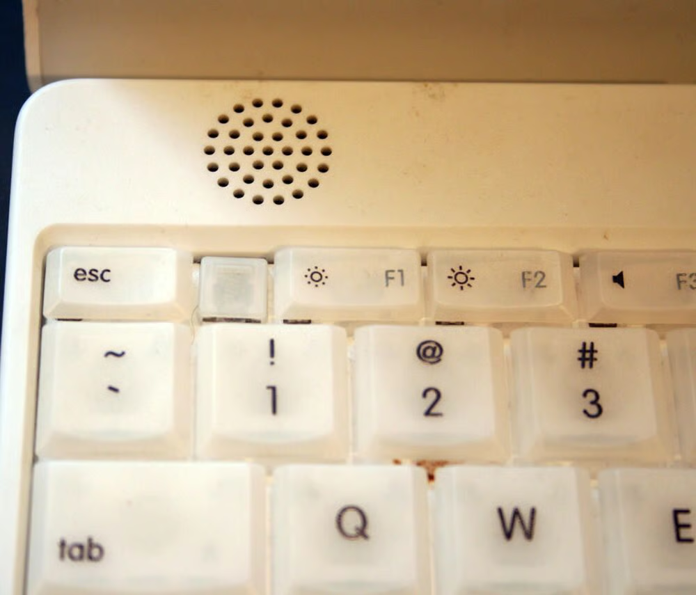
The second keyboard retaining tab sits in between the ESC and F1 key. These keyboard retaining tabs must be pressed backward (using a small flathead screwdriver) to remove the keyboard.
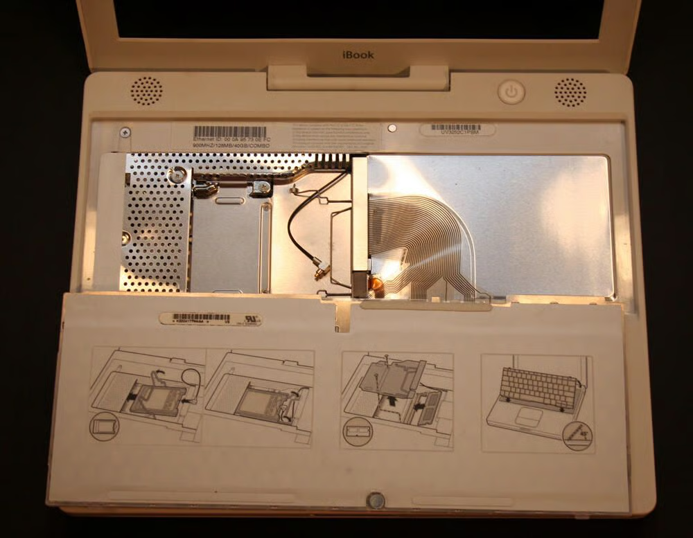
With the keyboard retaining tabs depressed, the iBook’s keyboard can be rolled backward. In this image, the keyboard has been rolled back on the laptop’s palm rest and track pad.
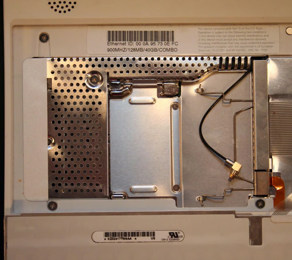
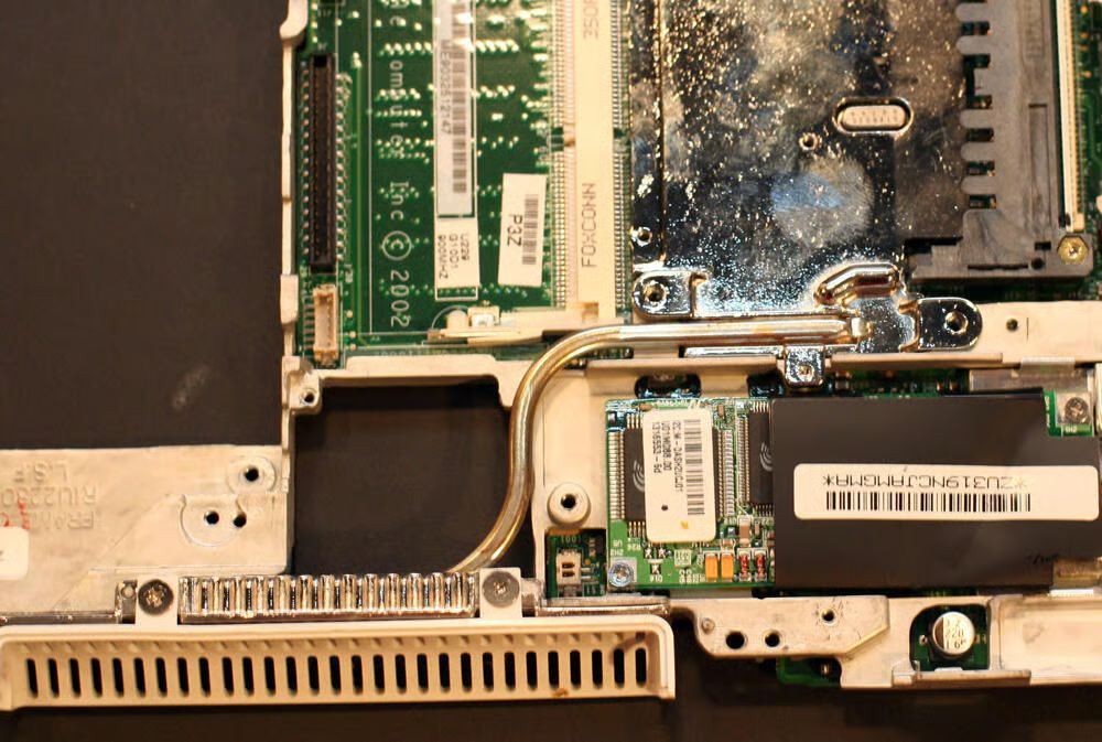
Were this unit equipped with an AirPort (wireless) card, the device would have been installed here. Note you can see the antenna cable, with the black cable and silver and gold tip, is present.\n\nHere you can also see the RAM shield, the silver cage that protects additional RAM installed in the system (the expansion bay lies behind this shield).
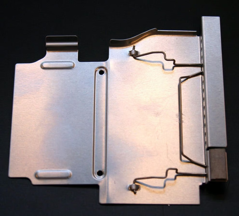
Here’s a closer look at the RAM shield once removed from the laptop.
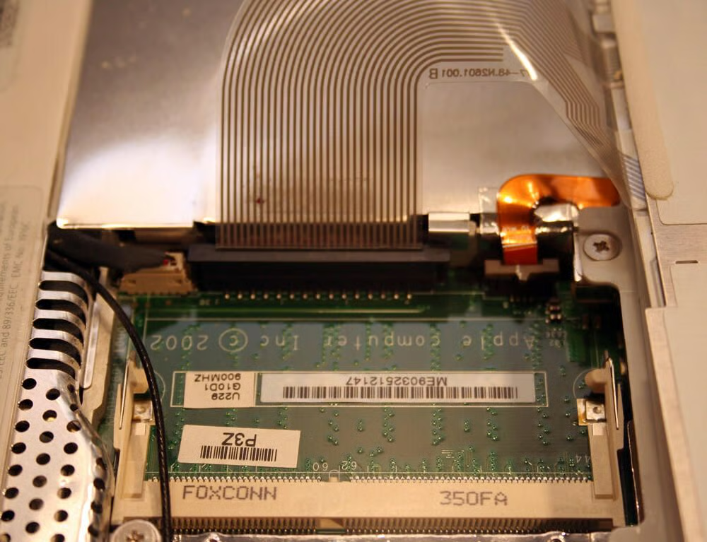
This second-generation G3 iBook shipped with 128MB of SDRAM soldered onto the motherboard. This expansion bay accommodated up to 512MB of additional 144-pin SODIMM memory.
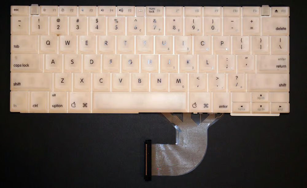
In this image of the iBook keyboard, you can see its data cable (that connects the keyboard to the system board) at the bottom.
Separating the iBook’s casing requires patience (and many sites recommend a spudger, or special delicate probe/separation tool).
Several tabs, such as this one within the battery compartment, must be depressed to separate the bottom casing from the iBook’s chassis.
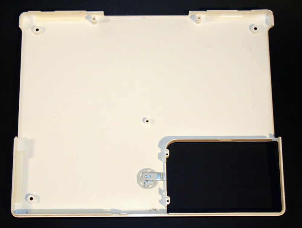
The bottom case, once removed from the iBook, looks like this. The circular object toward the bottom center of the image is an inside view of the battery compartment’s locking ring.
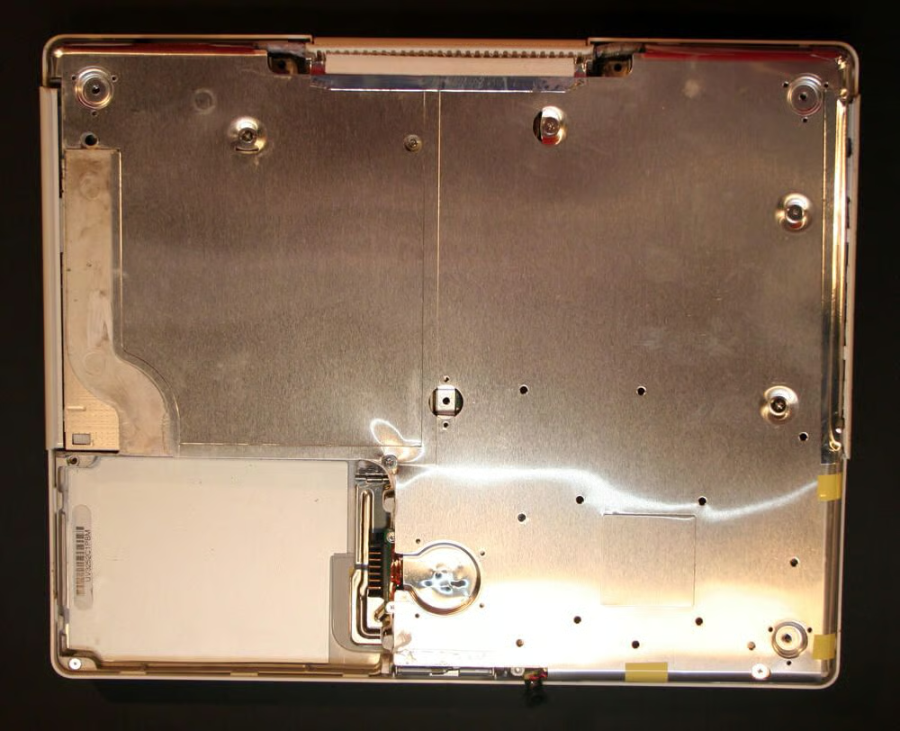
With the iBook’s white polycarbonite bottom casing removed, the metallic shield protecting the CD/DVD drive and motherboard becomes visible.
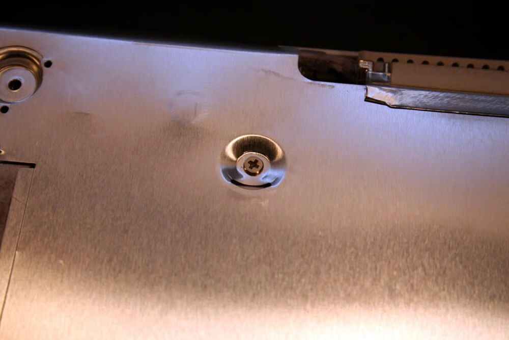
To remove the metallic shield, several Philips screws must be extracted.
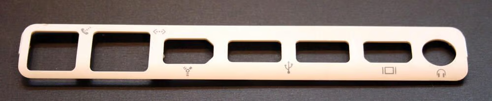
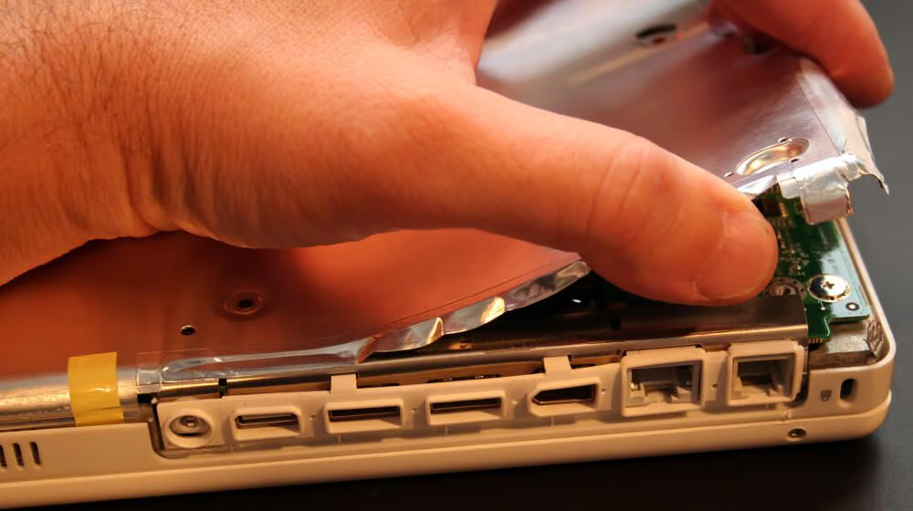
As the iBook’s white plastic casing is removed, this trim piece that encapsulates the laptop’s external ports can be pried loose from the chassis.
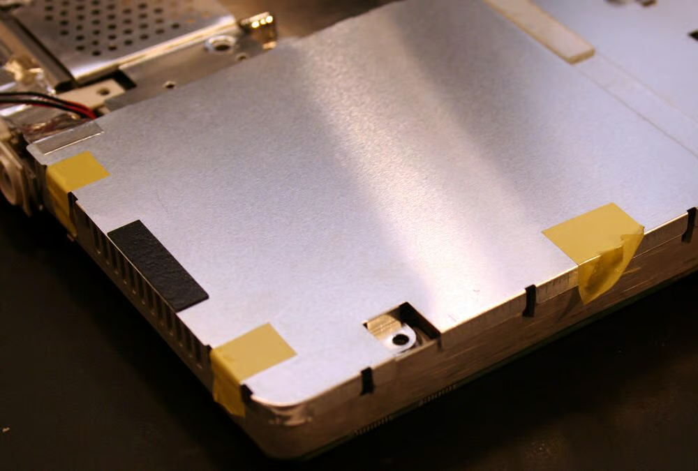
Once the Philips head screws are extracted from the metal shield, several taped edges must be freed. Here you can see I just pulled the shield gently to separate it from the rest of the unit (although several pieces of the yellow tape, shown here, needed to be cut).
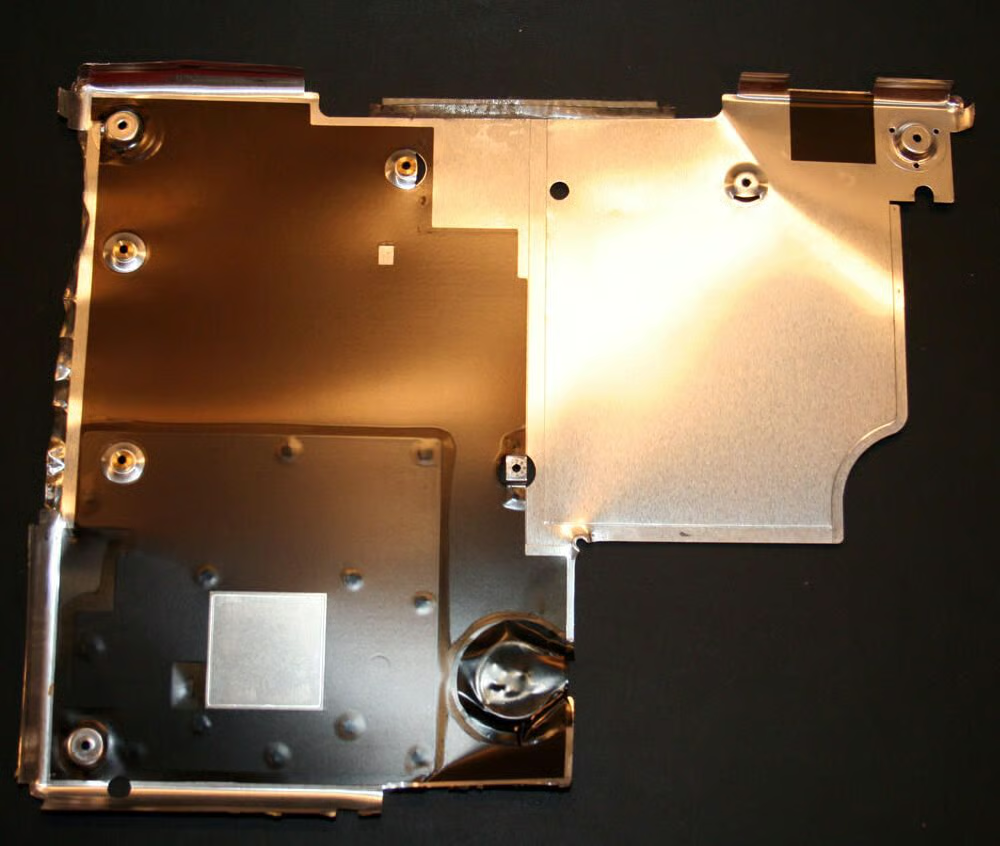
Here’s the bottom metal shield, once removed from the iBook.
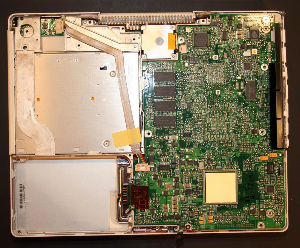
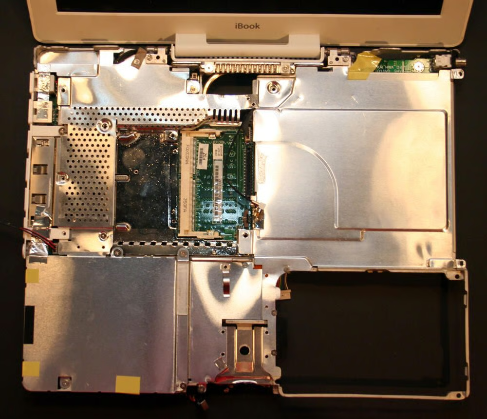
Removing the bottom shield reveals the iBook motherboard. You can also see the bottom of the CD-RW/DVD-ROM drive to the top left. The power cable, that connects the iBook’s power port to the motherboard, is taped against it.
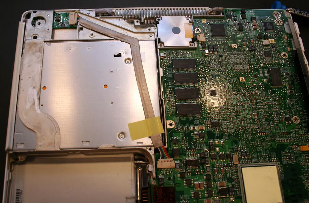
Visible here, in addition to the bottom of the CD-RW/DVD-ROM drive to the top left, is the system’s cooling fan (the silver square toward the top center) and the onboard RAM (the four blocks toward the image’s center).
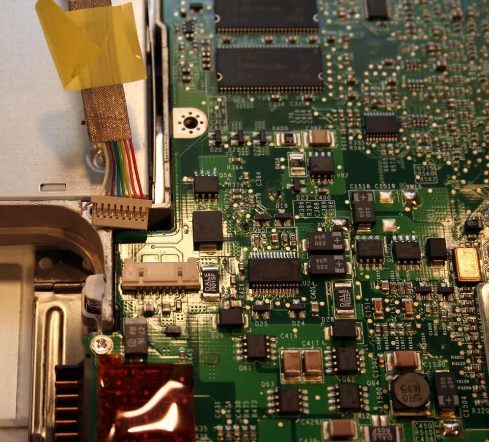
Here you can see the iBook’s power cable has just been disconnected from the system board.
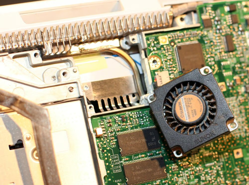
The iBook was cooled by a 35mm cooling fan manufactured by Sunon (in Taiwan).
A key Philips head screw, which must be removed to continue disassembly, sits behind this magnet. The magnet itself serves to help secure the iBook’s keyboard, when in place. It must be pried out using a flathead screwdriver.

With the keyboard retention magnet removed, the Philips head screw becomes visible.
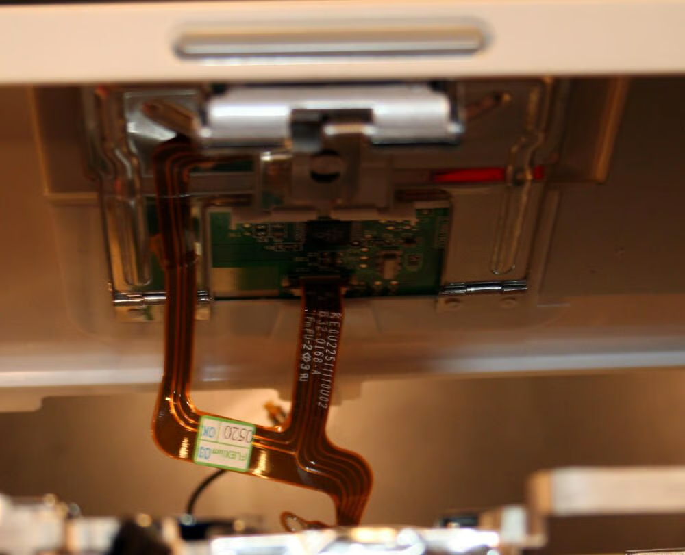
The iBook’s Trackpad electronics, and data cable, become visible once the upper case top polycarbonite shell is removed.
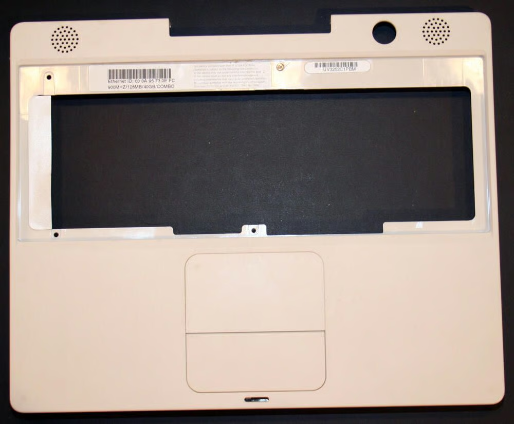
Here’s the iBook’s top polycarbonite shell, once removed from the iBook chassis.
The iBook’s main metal chassis is much more visible with the top polycarbonite shell removed. Also visible is a top-side metallic shield, which protects the system’s motherboard, hard disk and CD-RW/DVD-ROM from the top.
Several screws must be removed, and taped edges unfastened or cut, to remove the top shield.
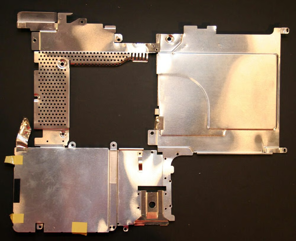
Here’s the top shield, once removed from the iBook. The top shield sits under the keyboard, Trackpad and palm rest and protects the motherboard, optical drive and hard disk.
With the top shield removed, the iBook’s hard disk is revealed.
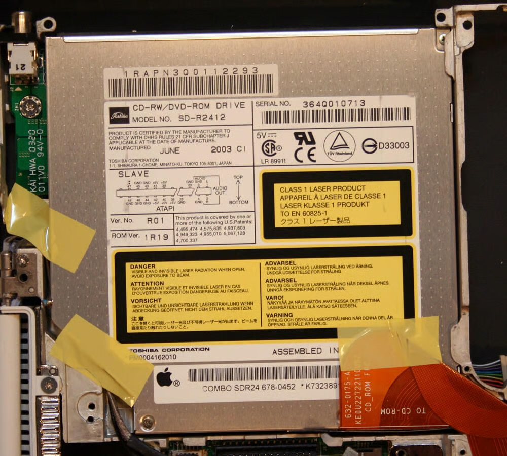
With the top shield removed, the top of the optical drive is also revealed.
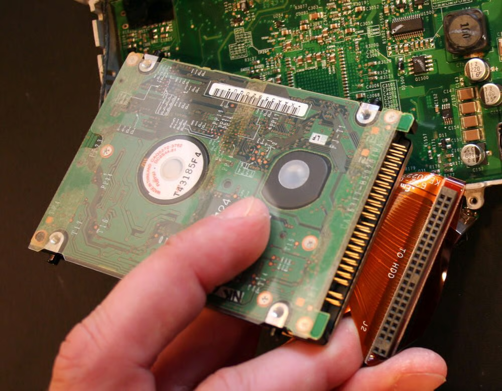
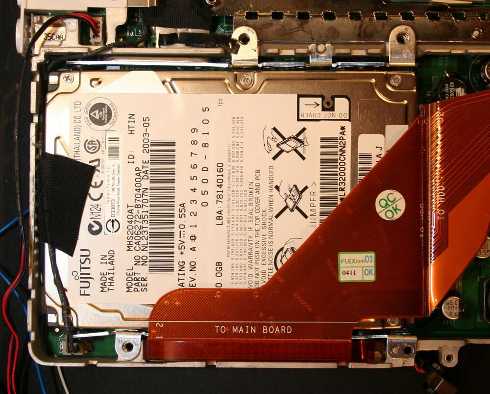
The IDE hard disk drive data and power cable must be disconnected before the hard disk can be removed from the Mac laptop.
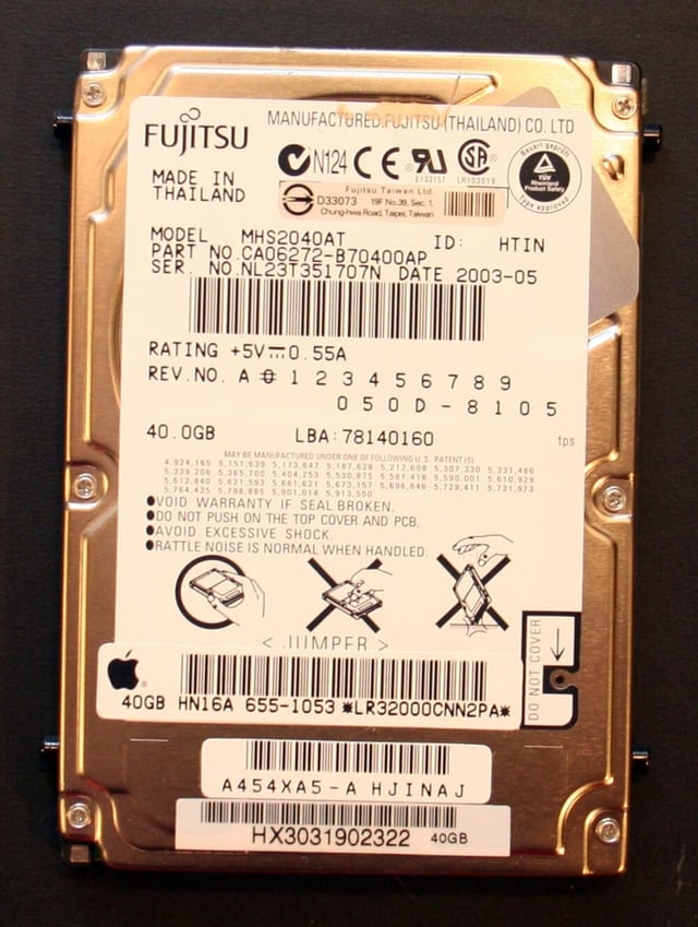
This G3 iBook, distributed in early 2003, featured a 40GB hard disk. The disk, model number MHS2040AT, was manufactured in Thailand in May 2003.
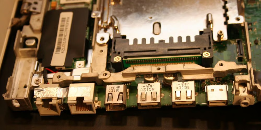
Integrated on the motherboard, as with most every laptop, are the Apple’s modem, Ethernet, FireWire, USB, video and audio ports.
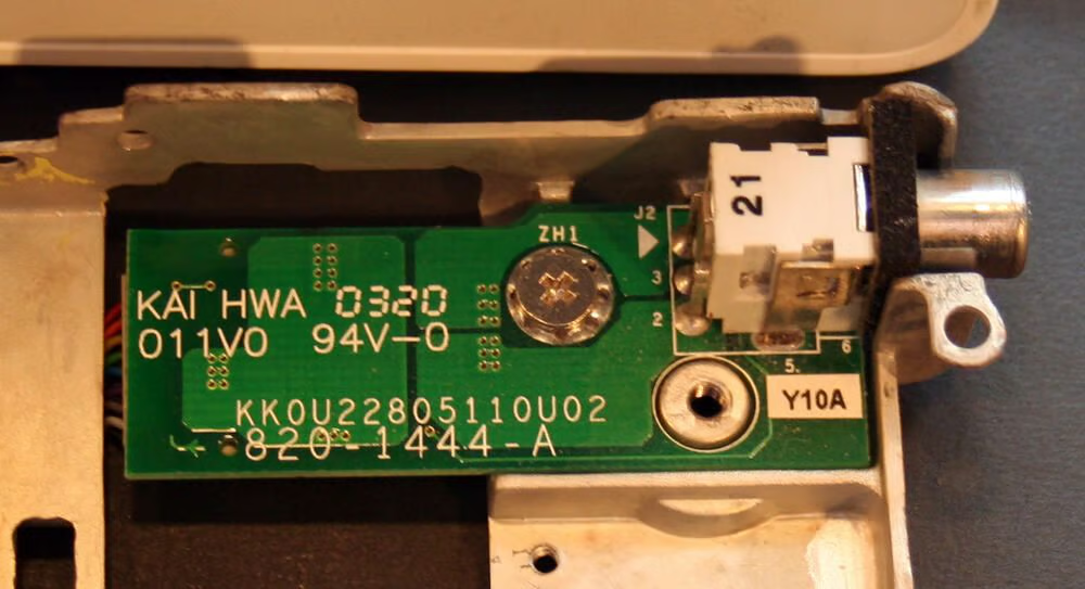
The iBook’s power port (and DC-In board). This is where the iBook’s power adapter plugs in to the laptop not only to provide the laptop with electricity but to also recharge the battery.\n\nThe power port is a notoriously vulnerable connection on laptops. Through heavy use, the ports can sometimes separate from their circuit board, requiring resoldering or replacement.
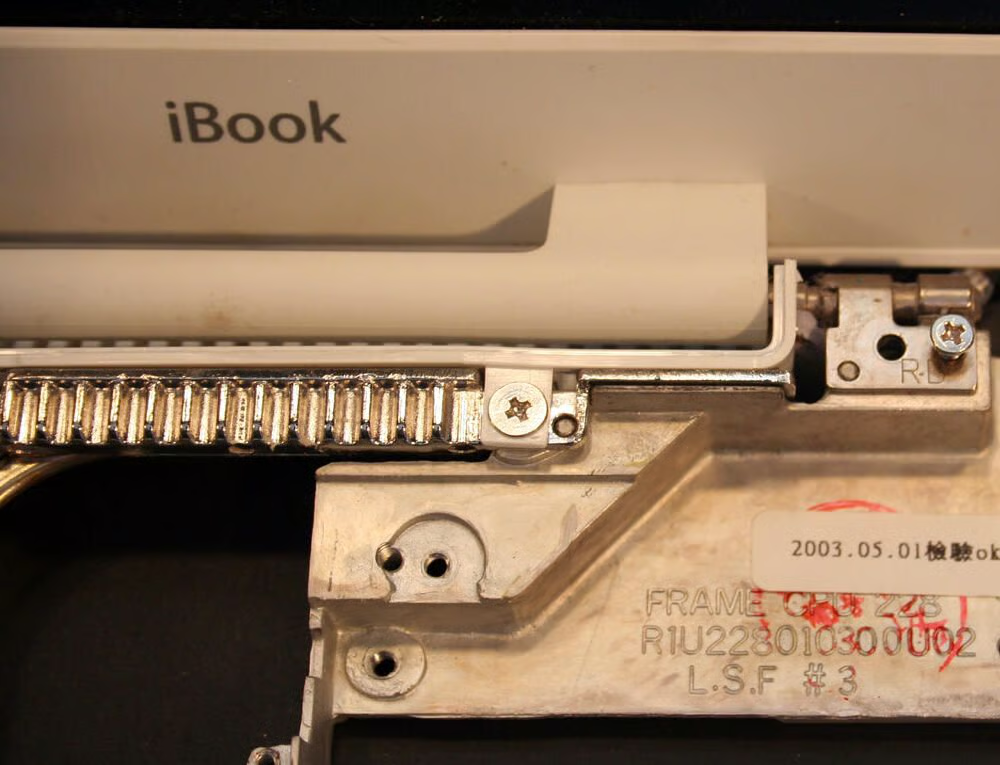
Several screws must be removed from the Apple’s chassis to remove the LCD.\n\nIn addition, in this image you can see the metal heat sink blades (seen beneath the iBook lettering) that help draw heat from inside the iBook outside the unit. The heat sink’s goal was to transfer heat from the logic board and via a thermal transfer pad away from the heat-generating components.
Here’s a look at more of the iBook’s heat sink.
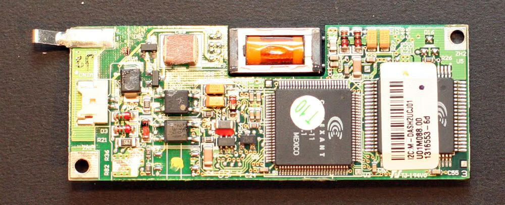
Here’s an old school modem, a V.90 56K unit manufactured by Conexant.
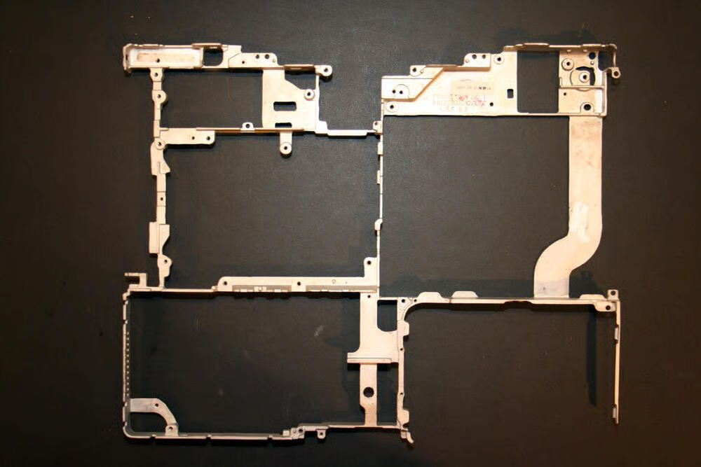
This is the main metal chassis that provides support and rigidity to most all the internal components. This chassis sits between the top and bottom polycarbonite shells.
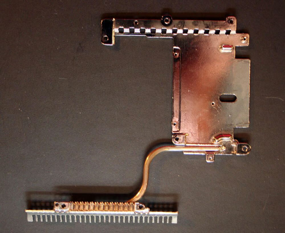
Here’s a close look at the heat transfer pad and heat sink, once removed from the main logic board.
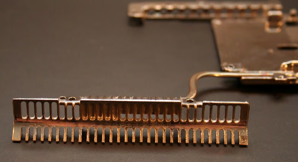
This is a close up look at the heat sink’s metal blades.
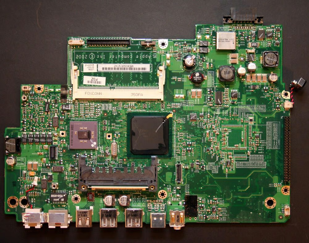
This is the iBook’s main motherboard, once removed from the Mac’s chassis. The logic board carries Apple’s name as the brand (copyright 2002) and lists the model number as KK0U22801110U02. The part number is 820-1419-A.
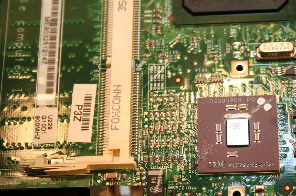
In the bottom right of this image the IBM Power PC chip is clearly visible. This unit, the PPC750FX, ran at 900MHz, featured 512k on-chip L2 cache and boasted 100 MHz bus speed.
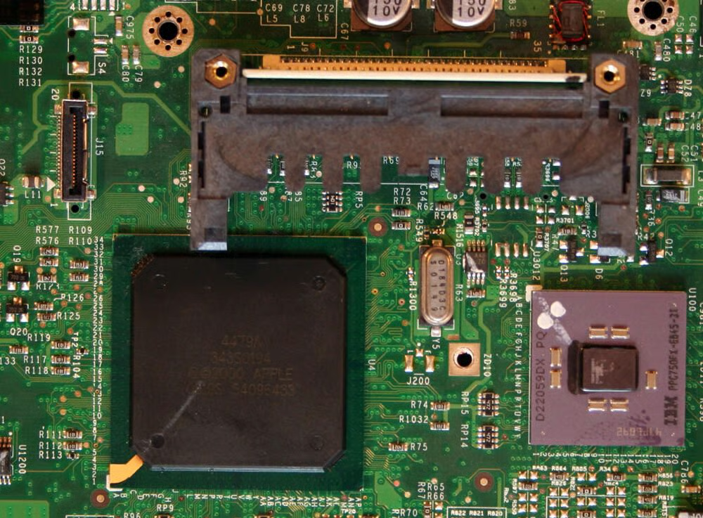
Apple’s 4479A semiconductor sits prominently on the logic board adjacent to the PowerPC CPU. The 4479A chip is the large square black box to the left of the IBM chip. If my research is correct, this chip served as memory and I/O device controller.
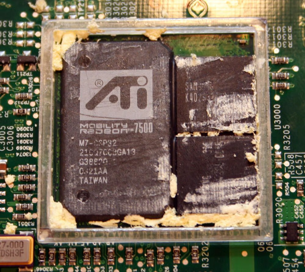
This is the ATI graphics microchip with the thermo foam removed.\n\nThe 900 MHz G3 iBook featured an ATI Mobility Radeon 7500 graphics chips. This ATI model boasted 32MB of video RAM.
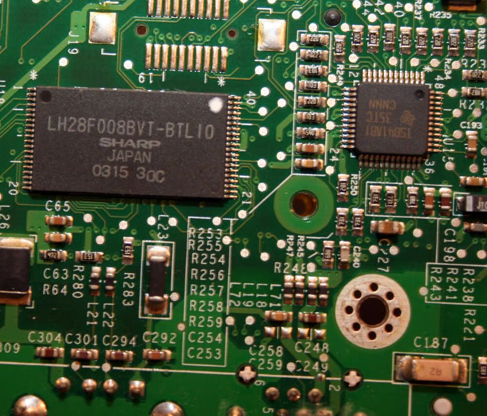
This is Sharp’s LH28F008BVT-BTL10 flash memory microchip. On the Mac G3 notebooks, this flash memory held the iBook’s Boot ROM instructions.
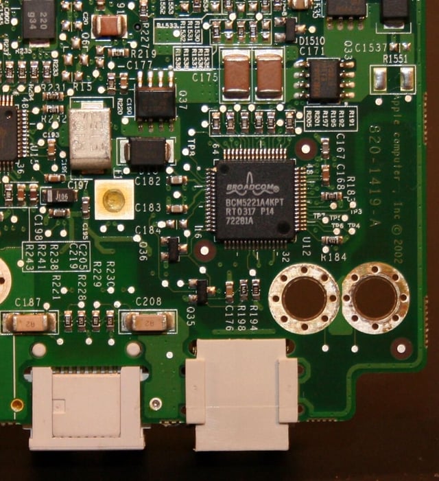
The iBook’s Ethernet connectivity is powered by this Broadcom microchip (model number BCM5221A4KPT).
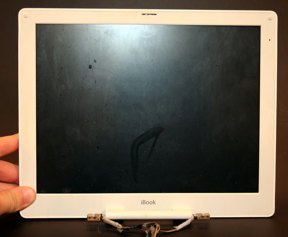
The iBook LCD, once removed from the main laptop chassis.
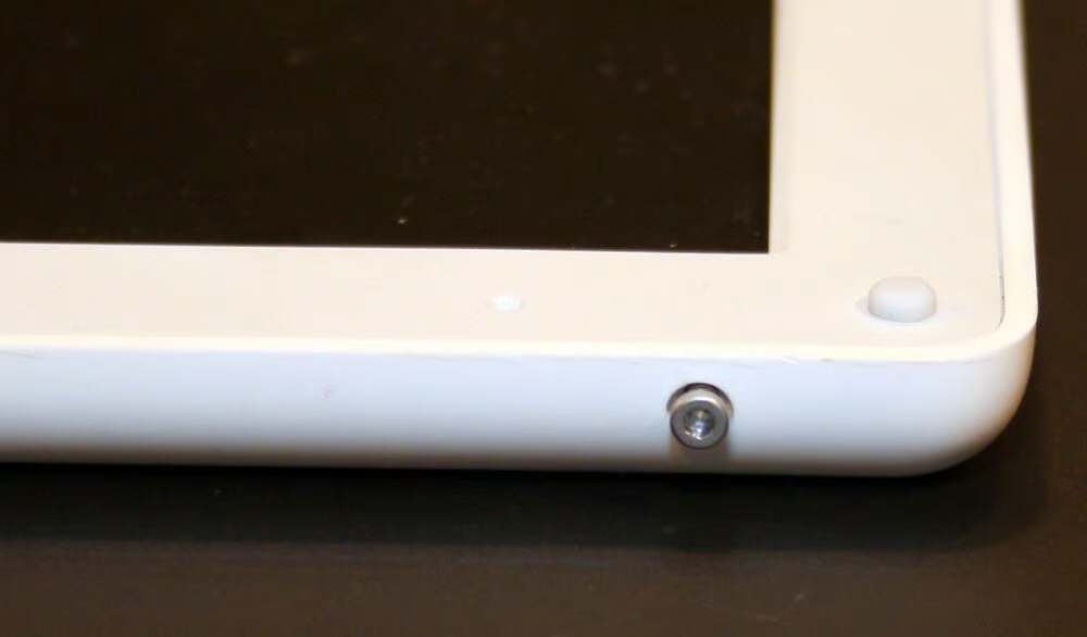
Several Torx screws, found on the side of the iBook’s lid, must be removed to continue disassembly of the LCD.
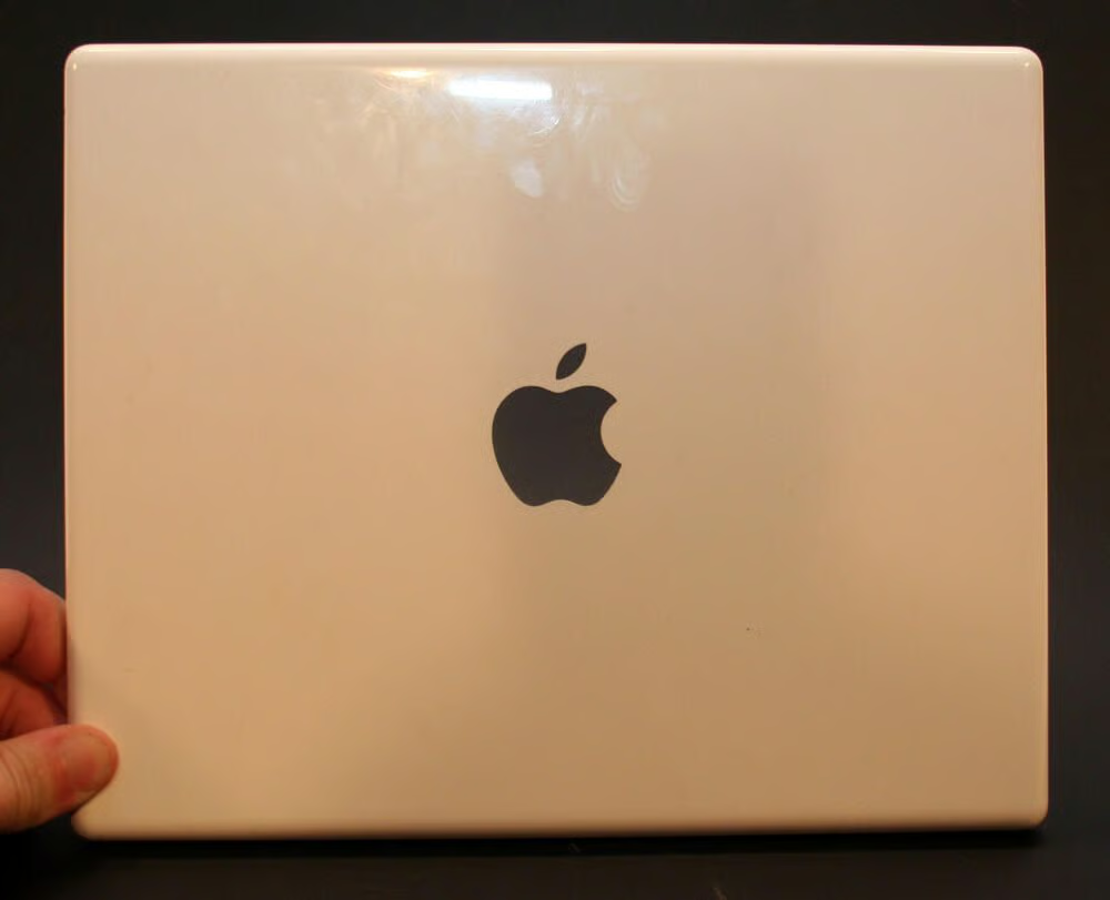
The Apple Mac top cover, featuring the cut-out Apple logo, once removed from the LCD.
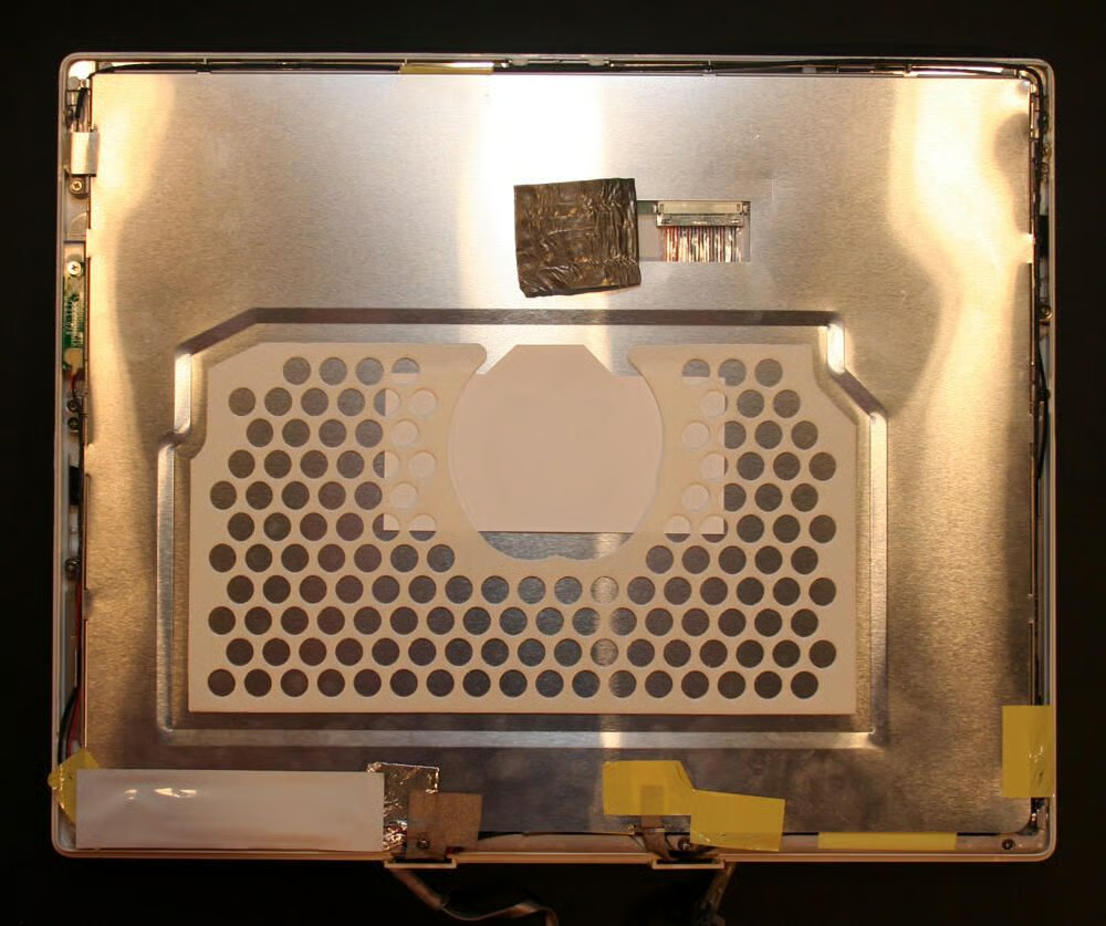
The metallic shield that sits inside the LCD cover.
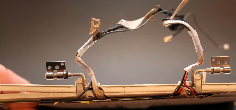
In this photo you can see the two hinges, and power and data cables, that connect the iBook LCD to the main chassis and motherboard.
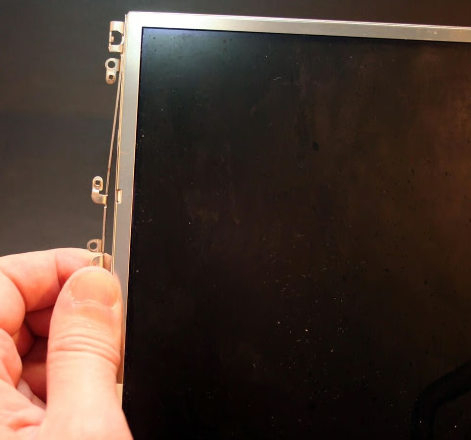
A custom cage secures the LCD inside the Mac’s polycarbonite case.
Here’s the LCD cage, once removed from the LCD display.
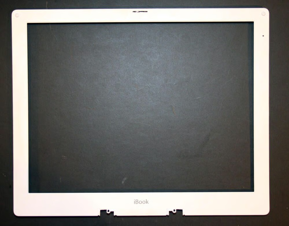
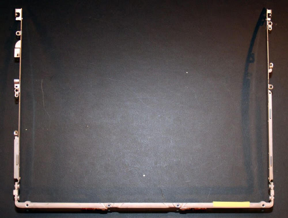
Here’s the LCD trimpiece, without the LCD, once it’s been removed from its other components (including the main bottom hinge mechanism).
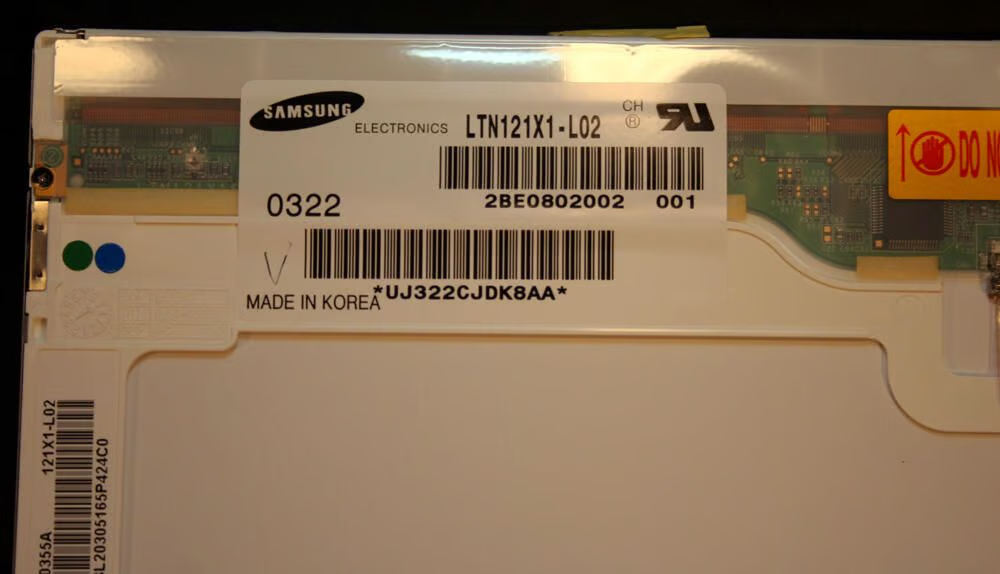
Samsung made the LCD displays used on the iBook. A Samsung Electronics display model LTN121X1-L02 graced this second-generation dual-USB G3 iBook. This display was made in Korea.
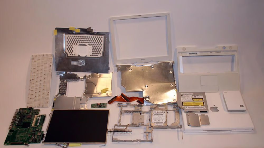
Here are most all the components that compose the Apple Dual-USB G3 iBook.

Erik Eckel is a managing partner at Louisville Geek and president of Eckel Media Corp. He previously served as Executive Editor at TechRepublic. He received Microsoft Engineer accreditation from Sullivan University and earned his Bachelor's Degree in English from the University of Louisville. He's earned Network+, Windows NT 4.0 MCP+I and MCSE, and Windows 2000 Professional MCP accreditations.


