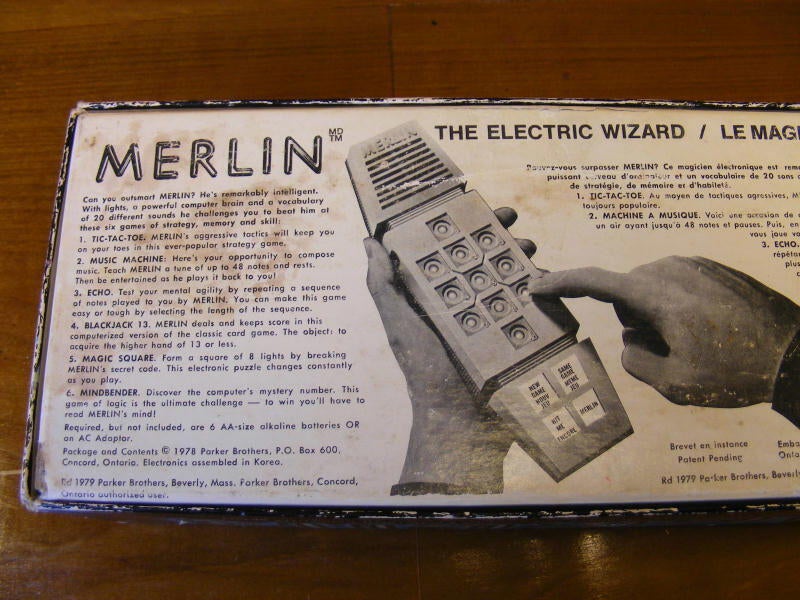
My guess is that this particular model was purchased in Canada, as it sports French as well. I focused on the English here – I’m sure the French won’t mind.
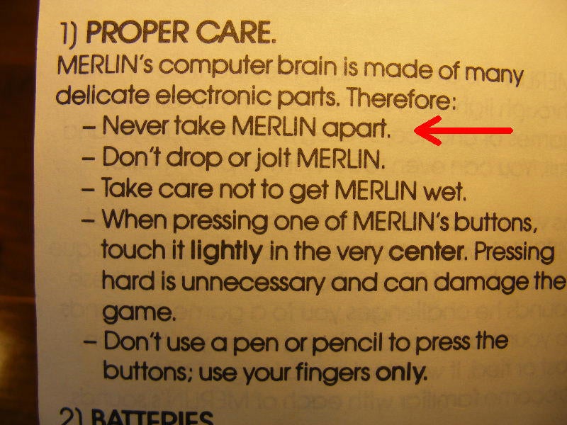
Nice – this should have been titled: Everthing that will almost certainly happen to your Merlin.
A co-worker named Dave told me that he left his out in the rain one night and it lived to play another day.
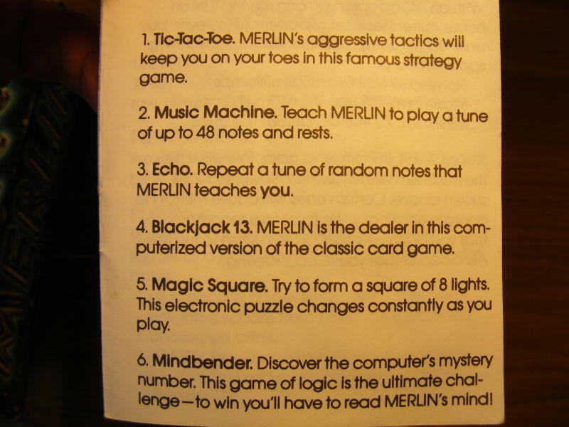
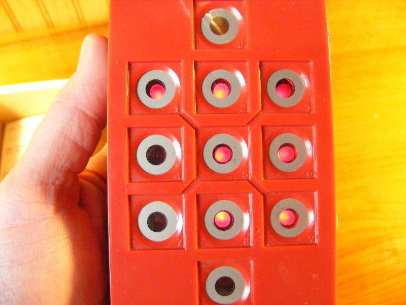
I never beat tic-tac-toe, and I never quite caught on to Magic-Square.
I saw this and had to include it.
I remember such a feeling of possibility when I realized that you could “compose music” on this device. I was lucky to memorize the first few chops of row-row-row your boat.\r\n\r\nIt was also a major downer when I realized that my masterpiece composition, which I had worked on for an hour, was obliterated after I powered it off.
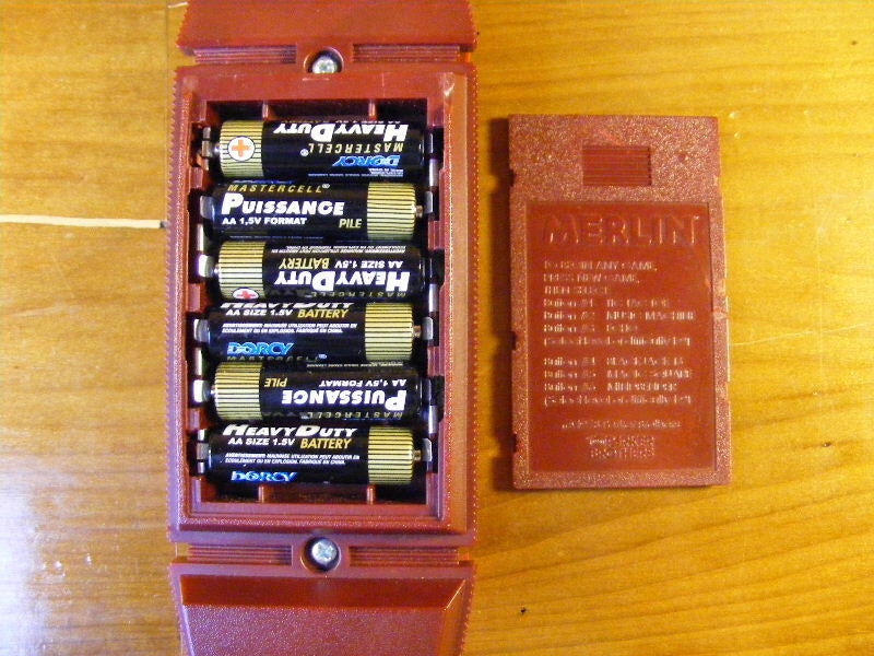
Here are our six penlight batteries – not included.
Also note the very useful listing of games and associated numbers on the cover panel – can’t see them too well here.
I started playing a game – but I don’t know which one here.
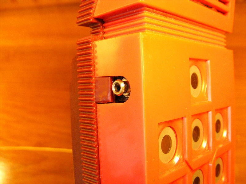
A view of the jack or the power adapter. You had to buy that separately, as indicated in the directions. Very specific, too:
Nominal: 9v DC @ 75milliamps
Minimum: 7.5v @ 150milliamps
Maximum: 10.5v @ 5milliamps
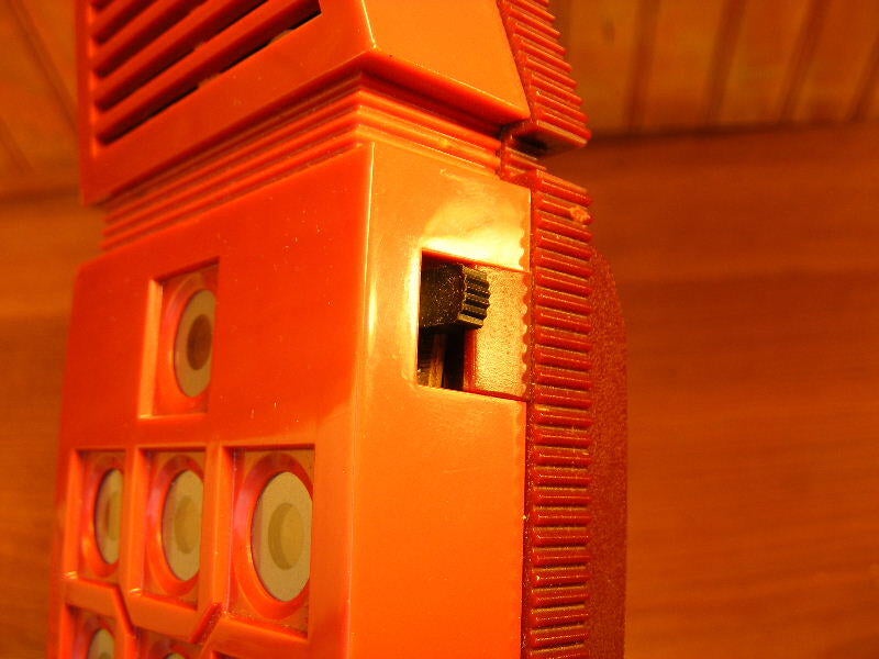
The power switch – I almost left this out.
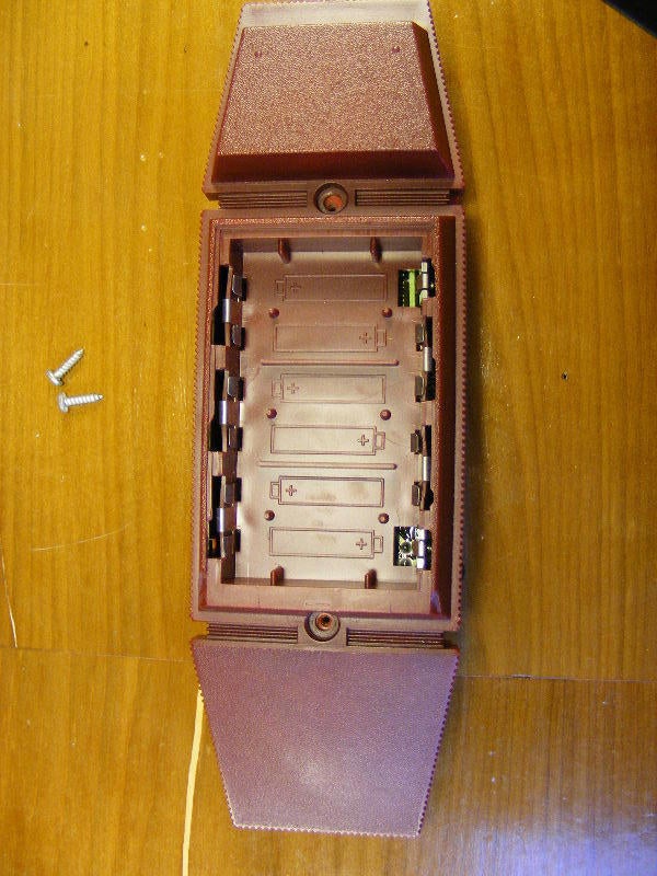
Here we have the only two fasteners in the device removed. Also see the enormous battery bay. 6 AA’s. Thats a lot of batteries. Could they have used a 9-volt instead?
It’s almost as if they designed the entire unit around “pen-light batteries”.
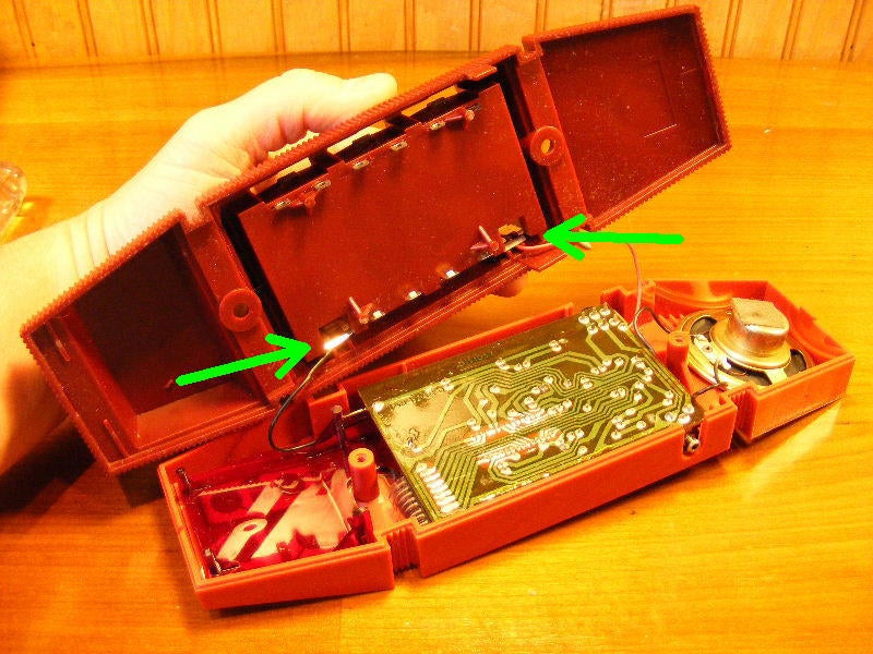
We need to remove the two power leads to the back of the case, where it picks up the juice from the “pen lights”.
Here is the lower half where you would make one of your four choices as to where the unit would go next.
Also note the sturdy feet to support the pounding that it would take.
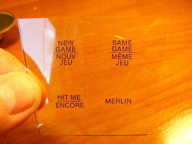
Here is the overlay that goes between the keypad membrane and the plastic stool that we just saw. With French translations.
On mine, it said “comp turn” instead of “Merlin” as does here.
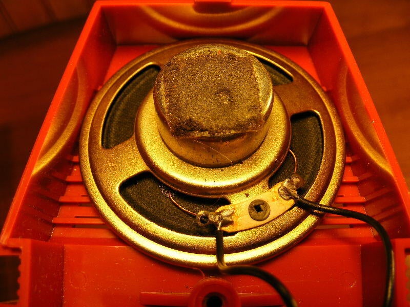
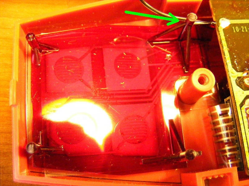
Here we have a solitary speaker. Note also that there are no screws holding it in. Minimalist engineers.
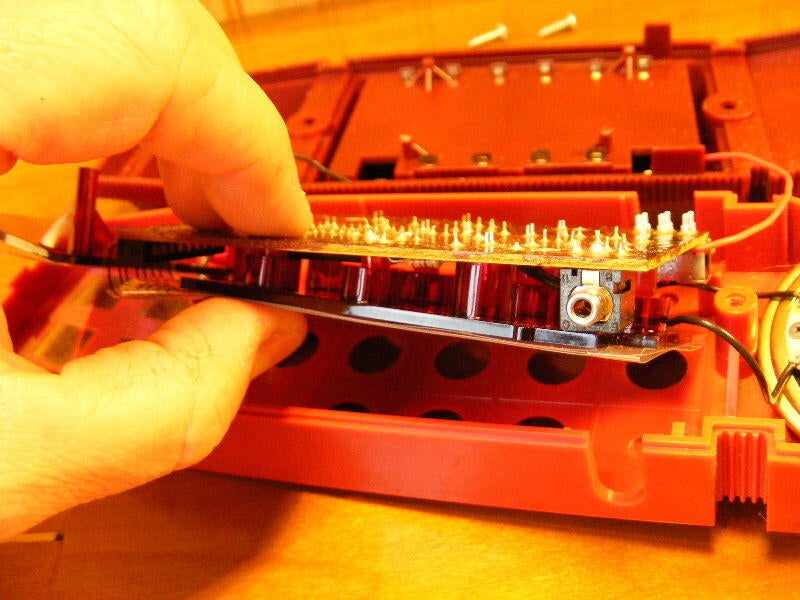
Taking out the mainboard and red plastic backrest.
Again – no fasteners here.
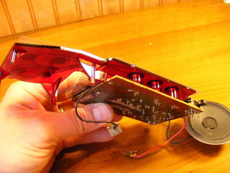
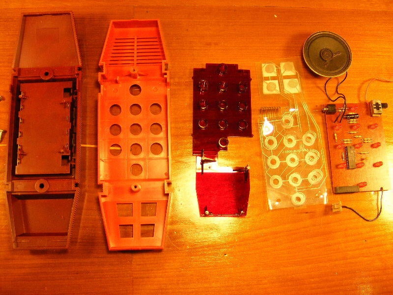
This is the entirety of the unit sans case.
With the touchpad still attached, we have a view of the board and the red lens/base, clamshell style.
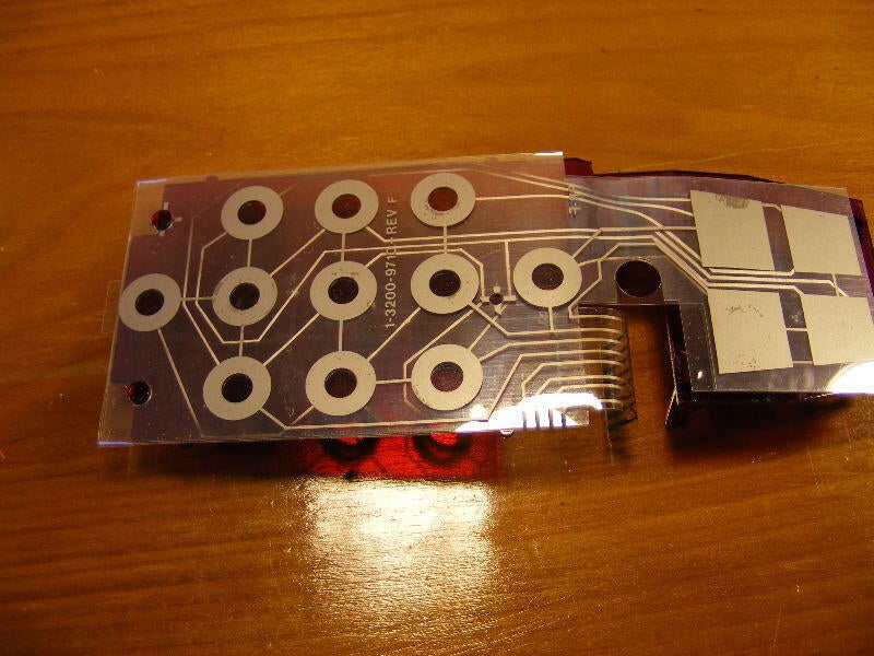
Now the mainboard has been removed (by simply pulling the ribbon out – nothing at all locking it in place), and this is how the touchpad is arranged on top of the red lens/base (still haven’t figured out what to call it).
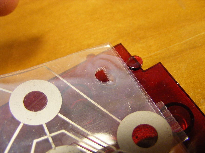
These little tabs are all that holds the touchpad in place and keeps it aligned.
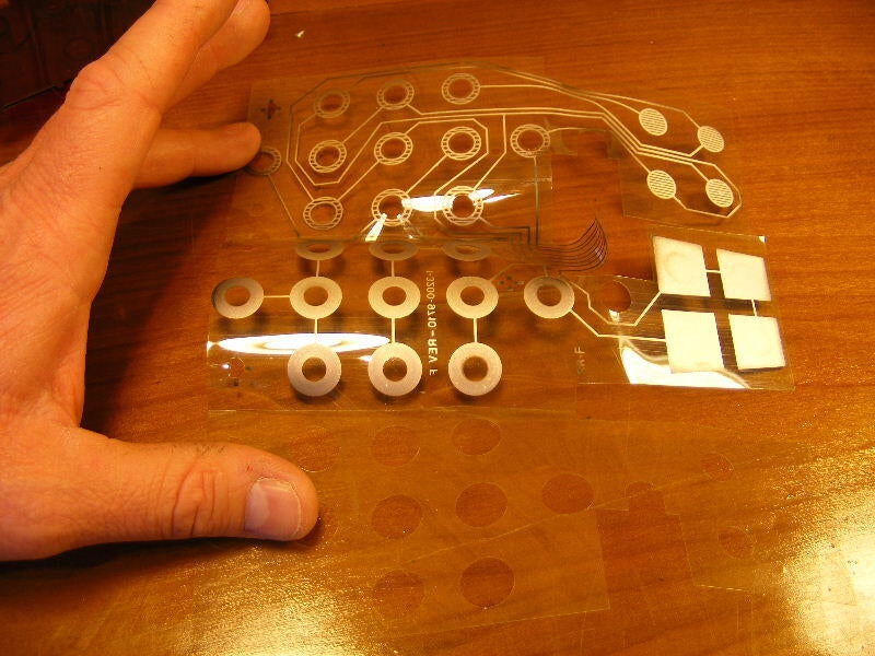
Simple design, our touchpad laid out for all to see. We get a good look here at the conductive material and the circuitry that makes it go.
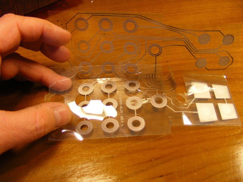
This shows how it folds together to make ‘er go. The unmarked plastic with holes folds in between the other two to provide separation when there is no pressure applied.
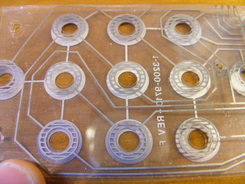
Assembled, this shows how the circuit is closed for each button by the two conductive sides making contact.
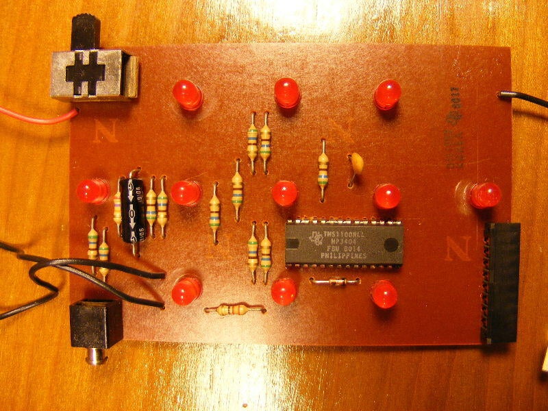
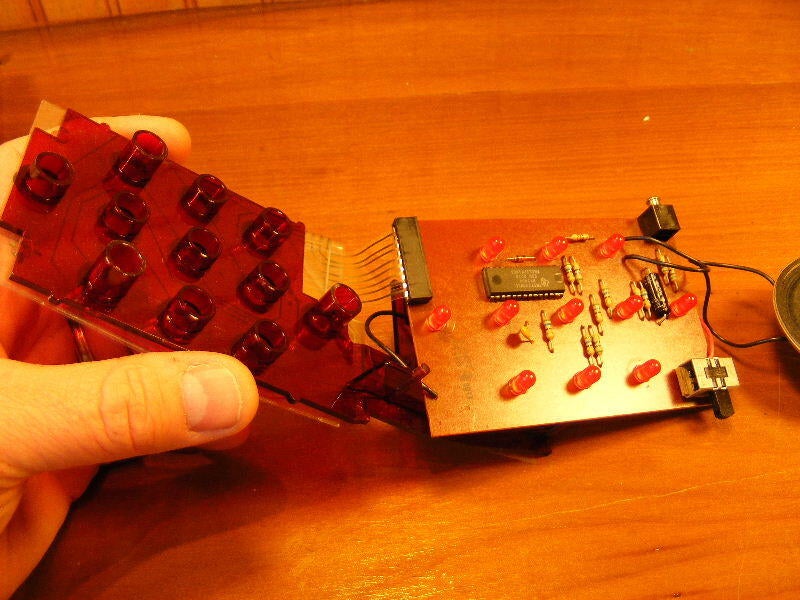
13 resistors, 2 capacitors, and a diode make up the lions share of the circuitry. Not to leave out the LEDs and the chip which holds our logic.
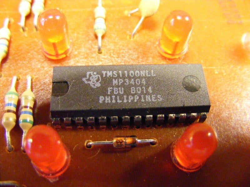
The Texas Instruments TMS1100 series chip. It funcions as both the ROM and the RAM. You can find the specs on it at an antique chips collectors page. Very common and still available, it seems.
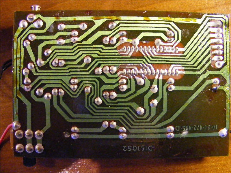
The backside of the mainboard. Certainly no multi-layered circuitboard here.
Here we have the complete unit all laid out in all of its simplistic, minimalistic wonder.
Thank-you, dear Merlin.
This has been the electronic equivalent of being an organ donor for education and nostalgic enrichment.


