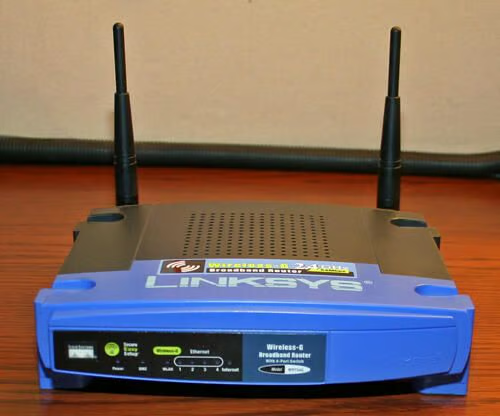
The Linksys WRT54G Wireless Router is one of the most common 802.11g devices deployed, a favorite of everyone from Linux fans to Windows users. Take a look inside what powers this ubiquitous device.
The Linksys WRT54G, which hit the market in 2003, boasts four 10/100 Ethernet network ports and a fifth 10/100 WAN port protected by Linksys’ firewall software.
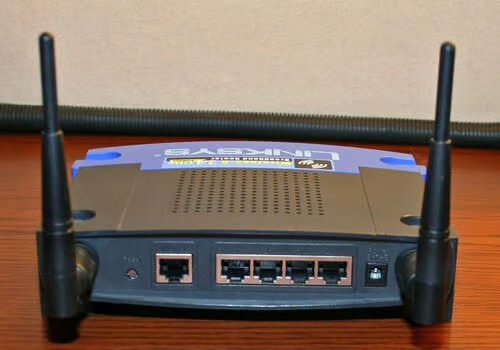
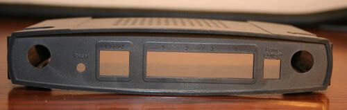
The four 10/100 Ethernet ports, and the protected WAN port, are easily accessible on the Linksys rear panel. A factory reset button is also present (far left), as is the power adapter plug (far right). Two antennaes, for powering 802.11 wireless communications, are readily evident as well.
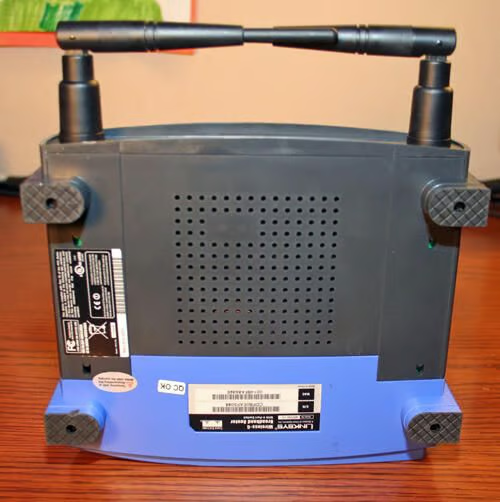
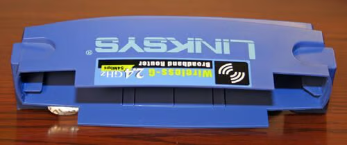
Cisco attaches model and serial number information on the WRT54G’s bottom-side.
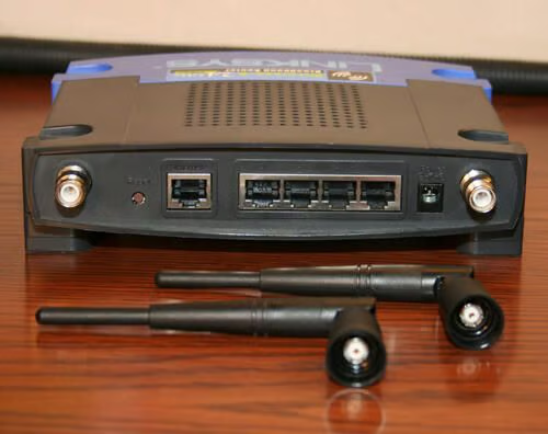
Antenna removal is easy on most Linksys 802.11 routers. Just unscrew both antenna from the main router unit.
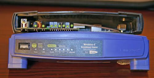
Forcefully pinching the front case on the Linksys WRT54G separates the front cover from the unit’s rear compartment. Removal requires that a tamper-proof sticker (bottom right) be separated from the case. Breaking the seal, of course, voids the manufacturer’s warranty.
Here you can see the front cover of the WRT54G removed from the main unit. Note the warranty-voiding protective seal toward the bottom left.
The pushbutton, typically hidden behind the Linksys front panel, enables Secure Easy Setup.
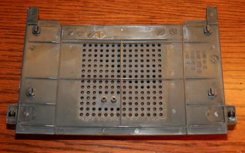
The main circuit board is easily separated from the rear cover shell. Here you can see the plastic rear shell by itself.
Removing the main circuit board’s two screws frees the asembly from the bottom panel, shown here.

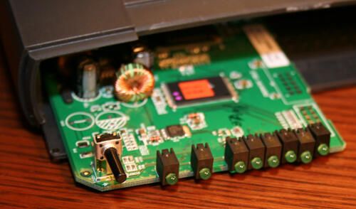
Here’s the main circuit board removed from the bottom panel. Note the capacitors (circled in red). The capacitors should be flat on top, as shown here. Rounded or leaking tops are a sign the unit suffered an electrical surge and needs to be replaced.

Wireless connections sprout from the main board, circled in red here. Note the first wireless antenna connection is integrated to the main board.
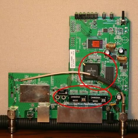
Circled on top are the Broadcom CPU that powers the Linksys WRT54G, as well as the Hynix RAM module. Below are various microchips that help manage the unit’s firewall, routing and network features.

Erik Eckel is a managing partner at Louisville Geek and president of Eckel Media Corp. He previously served as Executive Editor at TechRepublic. He received Microsoft Engineer accreditation from Sullivan University and earned his Bachelor's Degree in English from the University of Louisville. He's earned Network+, Windows NT 4.0 MCP+I and MCSE, and Windows 2000 Professional MCP accreditations.


