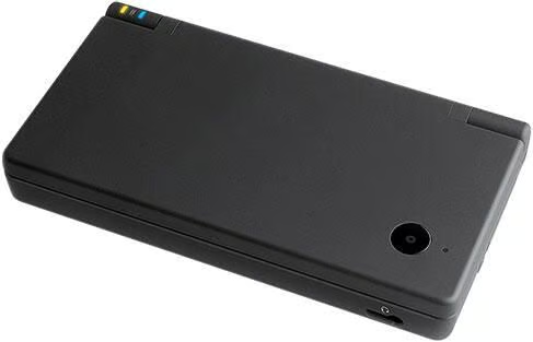
The Nintendo DSI is the latest hand-held game console. The DSi is a marvel of engineering and features a built-in camera.\n
The DSi emphasizes interactivity and offers game modes that involve the manipulation of images and sounds. Of course, you can play games and you can play those games with friends wirelessly.
\nWith the help of iFixit, TechRepublic presents this Cracking Open Photo Gallery of the DSi.
The original iFixit Teardown Gallery can be found here.
Image courtesy of Nintendo
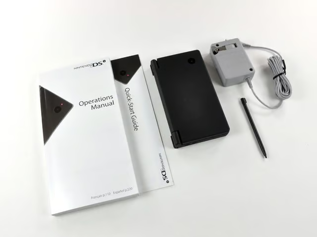
Its here! Its here! Whoopee!\n
\nContents of the box:\n
\n
\n
\n
\n
\n
Image by iFixit used by TechRepublic with permission.

An invitation from Mario’s hat to join Club Nintendo.
Image by iFixit used by TechRepublic with permission.
\n
\n
Image by iFixit used by TechRepublic with permission.
\n
\n
Image by iFixit used by TechRepublic with permission.
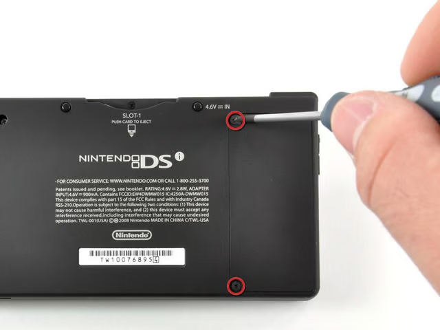
Two Phillips screws prevent access to the battery. They are easily dealt with using our custom-made screwdriver.
Image by iFixit used by TechRepublic with permission.
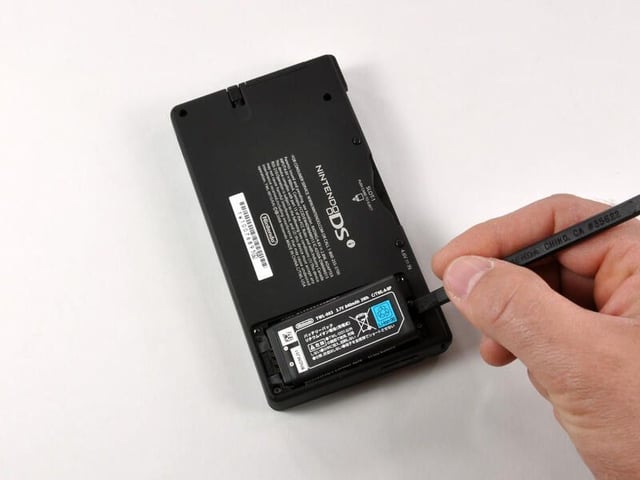
A quick flick of the spudger (or fingernail) dislocates the battery from its housing.
Image by iFixit used by TechRepublic with permission.
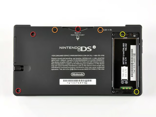
There are a total of seven screws that hold the lower case of the DSi together:\n
\n
\n
\n
Image by iFixit used by TechRepublic with permission.
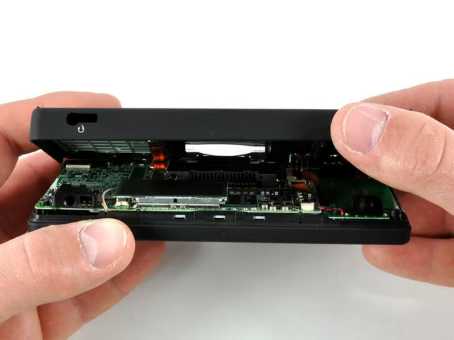
And just like that, the case comes open.
\nAn orange connector joins the cases together. Care should be taken when opening the DSi to ensure this connector is not damaged in the process.
Image by iFixit used by TechRepublic with permission.
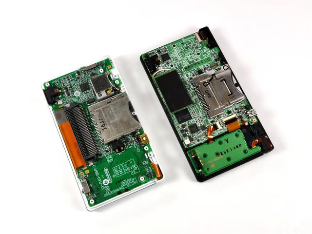
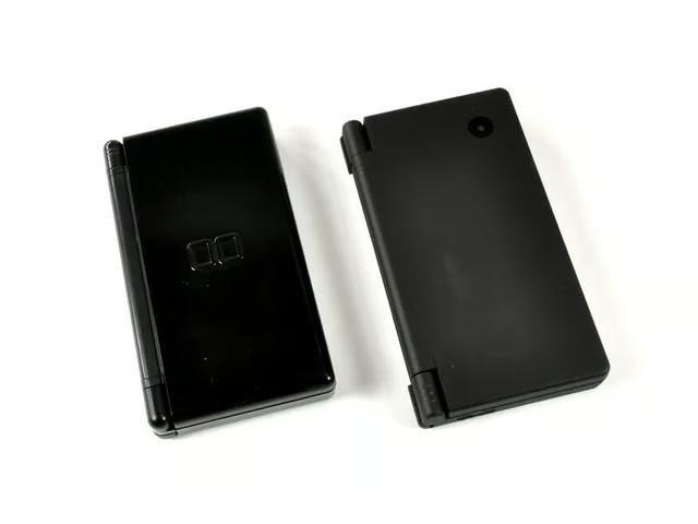
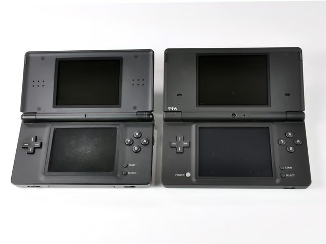
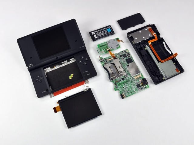
A comparison between the old and the new. There are definite differences between the DS Lite (left) and DSi (right).
Image by iFixit used by TechRepublic with permission.
Removing the battery PCB is a pretty straightforward procedure:\n
\n
\n
Image by iFixit used by TechRepublic with permission.
The Wi-Fi board is held in place via one large connector. A quick wedge-and-twist action of the spudger releases it from the main board.
Image by iFixit used by TechRepublic with permission.
Another flick of the spudger removes the Wi-Fi board’s connector wire.
Image by iFixit used by TechRepublic with permission.
Six connectors need to be disconnected prior to removal: five on the visible side, and one on the other side.
Image by iFixit used by TechRepublic with permission.
We are done with the first level of the disassembly.
Image by iFixit used by TechRepublic with permission.
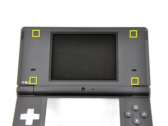
Four black plastic covers need to be removed to reveal the Phillips screws underneath.
Image by iFixit used by TechRepublic with permission.
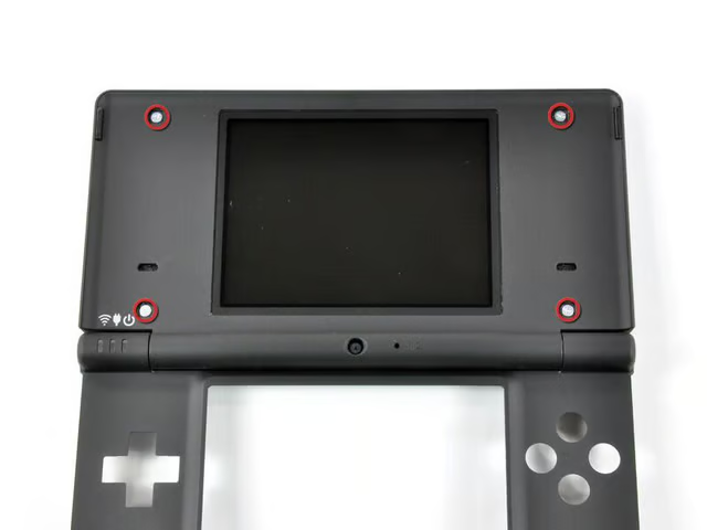
Removing the four Phillips screws allows access to the top display.
Image by iFixit used by TechRepublic with permission.
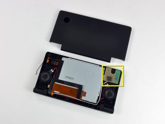
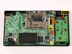
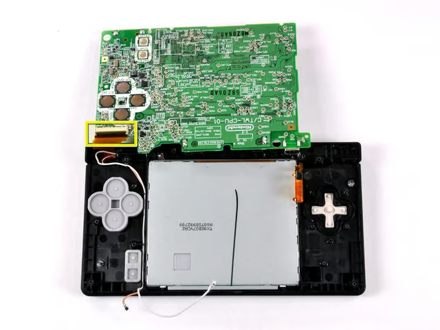
The antenna board for Wireless LAN is mounted in the upper right corner of the chasis.
\nThe ribbon cables for the top display and cameras are coiled and routed through the hinge between case halves. We’ll go ahead and add that to the list of parts we want to watch a robot assemble.
Image by iFixit used by TechRepublic with permission.
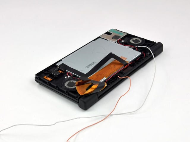
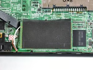
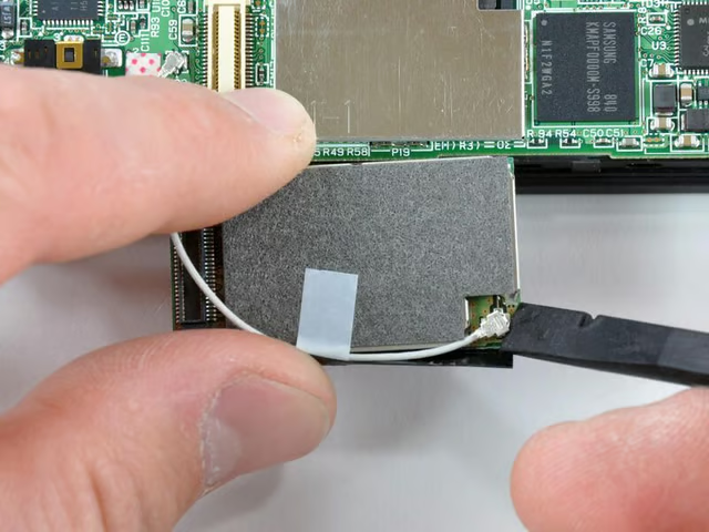
The thin orange wire seen in the second photo is for the microphone. Little DJs everywhere will drool over a new feature allowing users to distort the pitch and speed of music during playback.
Image by iFixit used by TechRepublic with permission.
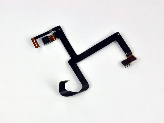
The DSi has two VGA CMOS digital cameras (0.3 megapixels); one on the internal hinge pointed towards the user and the other in the outer shell.
Image by iFixit used by TechRepublic with permission.
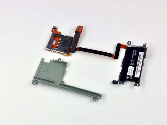
The DSi has an integrated SD/SDHC expansion slot. You can now use a normal SD card for the playback of AAC audio files and external storage of pictures or downloaded software. Can anyone say homebrew apps?
Image by iFixit used by TechRepublic with permission.
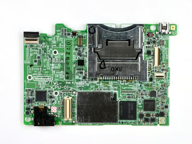
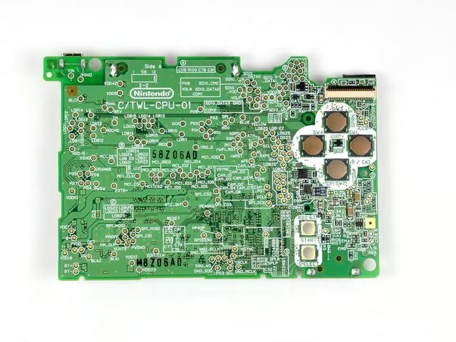
Lots of chips in a small area.
Image by iFixit used by TechRepublic with permission.
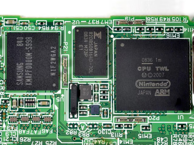
Chips of interest, left to right:\n
\n
\n
\n
Image by iFixit used by TechRepublic with permission.

Mark W. Kaelin has been writing and editing stories about the information technology industry, software, hardware, gaming, finance, accounting, and technology geekdom for more than 30 years.


