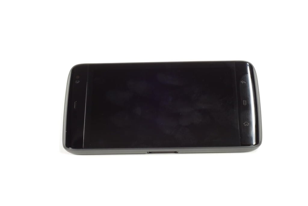
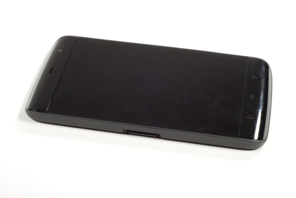
On the front of the Dell Streak are the LCD screen, ambient light sensor, front-facing camera lens, earpiece, proximity sensors, microphone, and main control buttons (Back, Menu, and Home).
From the orientation of the Back, Menu and Home buttons, it’s clear that the Dell designed the Streak to be help in landscape mode when not being used as a phone and help to one’s ear.
Photo credit: Bill Detwiler / TechRepublic
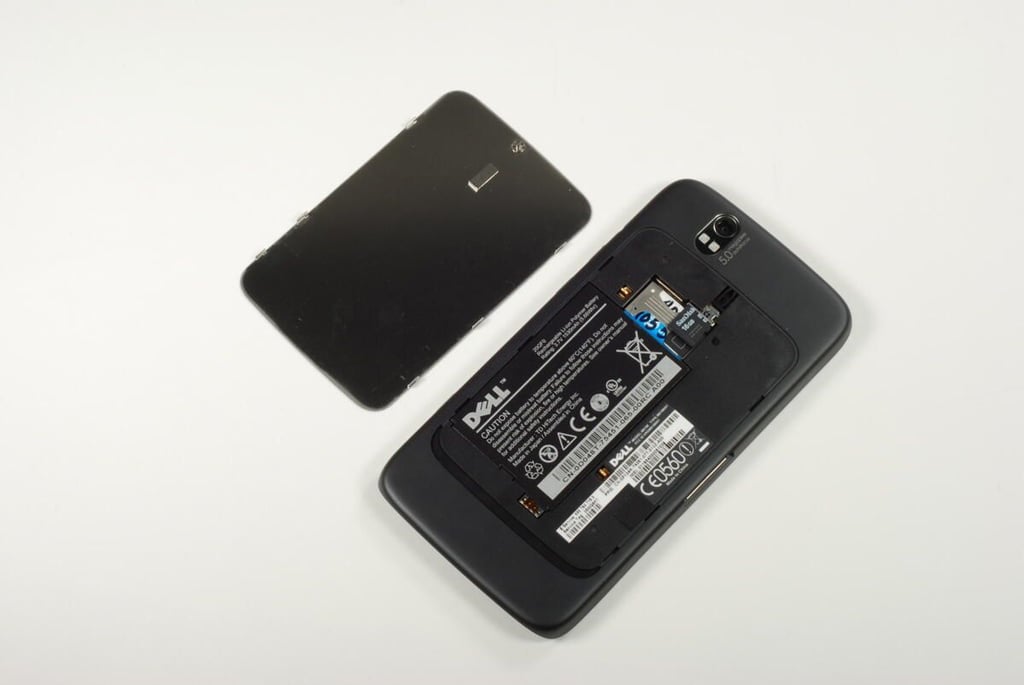
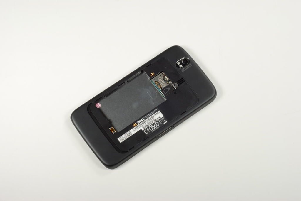
With the Dell Streak’s back cover removed, we can see the battery, SIM card, and micro-SD card.
Photo credit: Bill Detwiler / TechRepublic
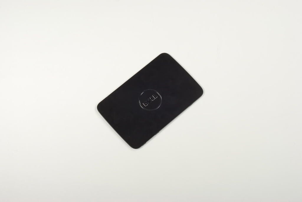
The Dell Streak’s back cover is made of metal.
Photo credit: Bill Detwiler / TechRepublic
Photo credit: Bill Detwiler / TechRepublic
With the battery, SIM card, and micro-SD card removed, we can begin removing the plastic case.
Photo credit: Bill Detwiler / TechRepublic
The Dell Streak’s plastic case is held to the front panel assembly with five T5 Torx screws. Unfortunately, the screws are hidden under the rounded, plastic bezels located on the top and bottom of the Streak. We will need to remove these bezels before removing the screws.
Photo credit: Bill Detwiler / TechRepublic
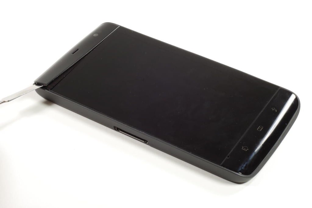
Using a thin metal blade or plastic case-opening tool, gently pry the first bezel loose. The thin plastic piece is held on with double-sided tape. You should be able to remove the bezel and leave the tape stuck to the plastic case. This will allow you to reattach the bezel when you reassemble the device.
Photo credit: Bill Detwiler / TechRepublic
Two T5 Torx screws are located under the top bezel.
Photo credit: Bill Detwiler / TechRepublic
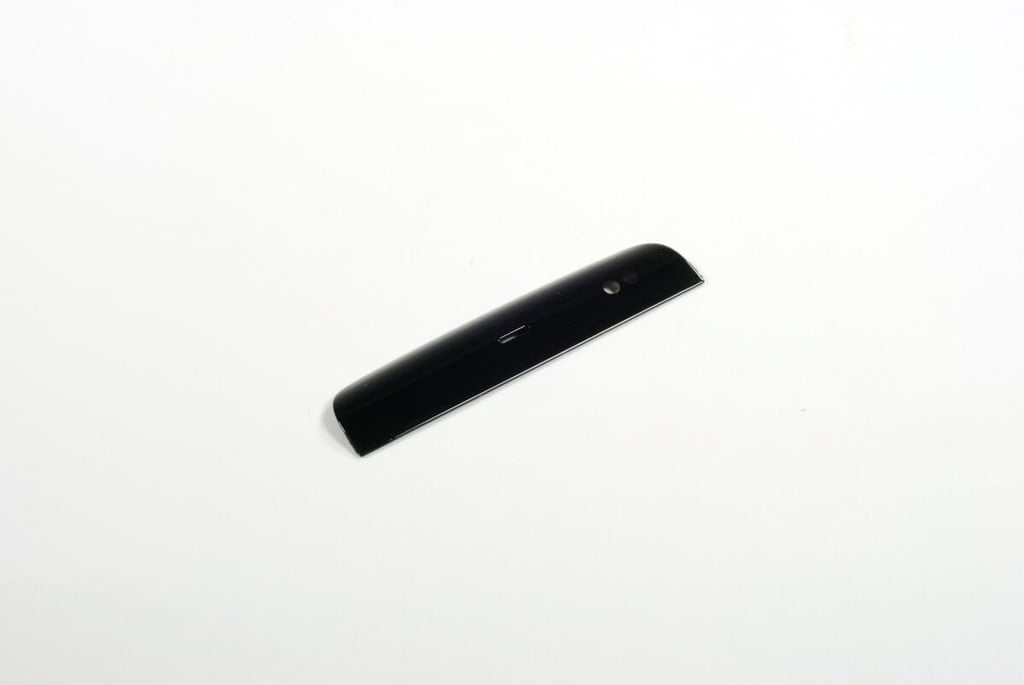
Photo credit: Bill Detwiler / TechRepublic
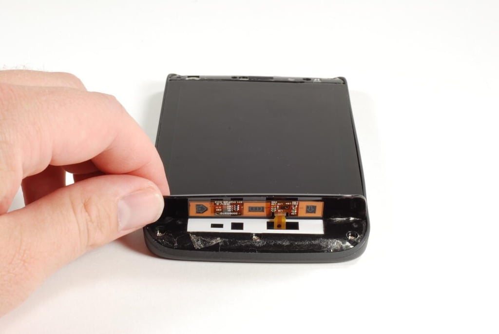
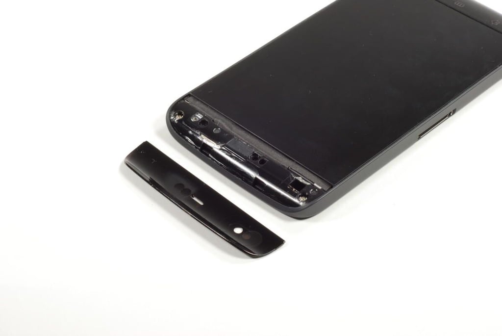
Using the same technique you used earlier, pry loose the bottom bezel. But take care. The bottom bezel houses the Dell Streak’s main control buttons and is attached to the device with a thin ribbon cable. At this point, you don’t need to remove the cable. Just lift the bezel up enough to reach the three T5 Torx screws located underneath.
Photo credit: Bill Detwiler / TechRepublic
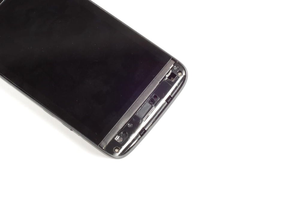
Photo credit: Bill Detwiler / TechRepublic
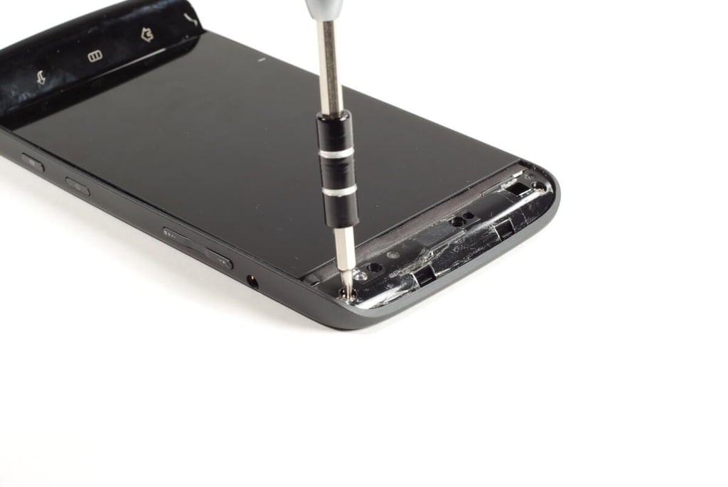
Photo credit: Bill Detwiler / TechRepublic
With the five T5 Torx screws removed, gently pry the rear case free from the front panel assembly.
Photo credit: Bill Detwiler / TechRepublic
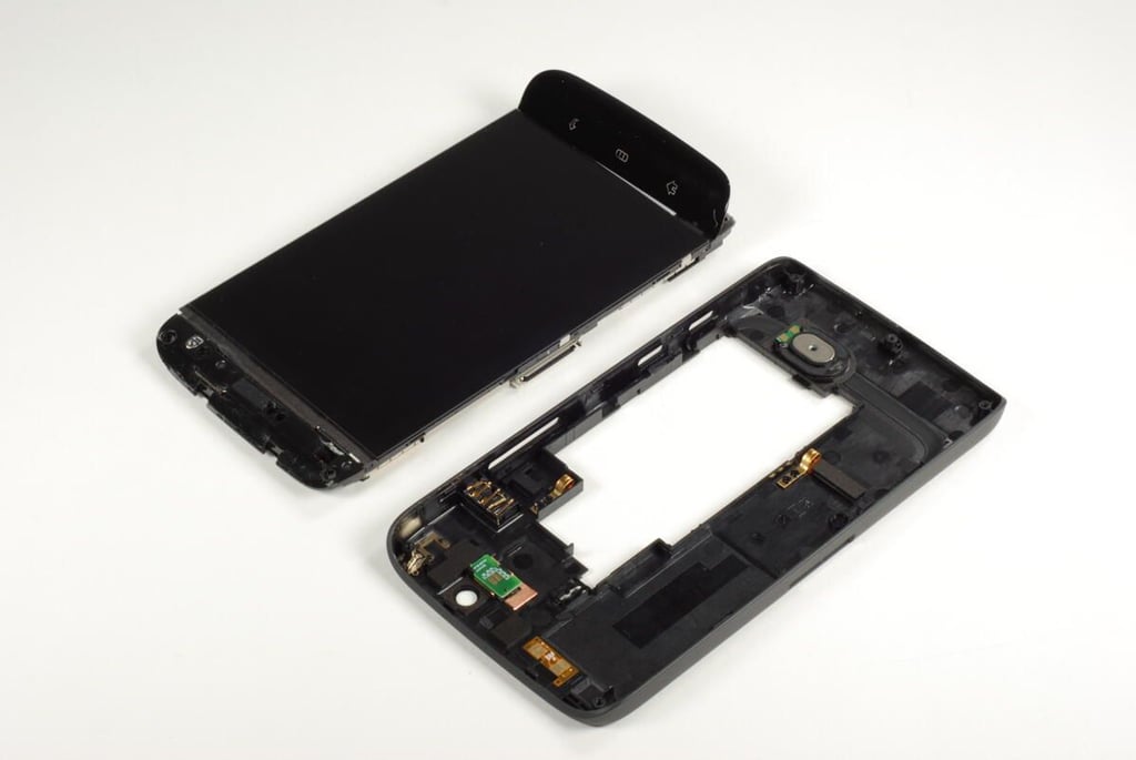
Photo credit: Bill Detwiler / TechRepublic
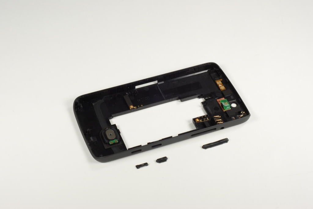
Be careful when separating the rear case from the front panel assembly. The power, camera, and volume up/down buttons are not fastened to the case and will likely fall out.
Photo credit: Bill Detwiler / TechRepublic
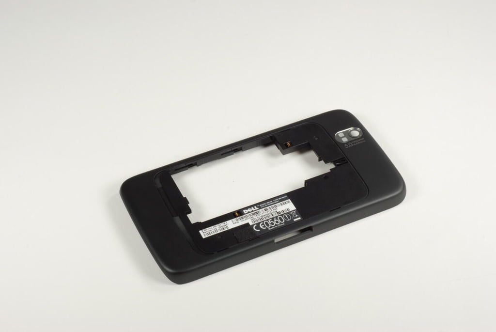
Photo credit: Bill Detwiler / TechRepublic
This small circuit board on the rear case is for the rear-facing camera flash.
Photo credit: Bill Detwiler / TechRepublic
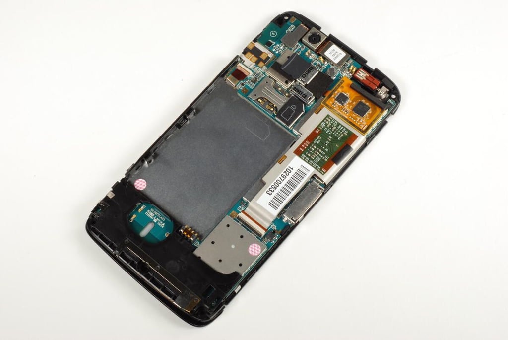
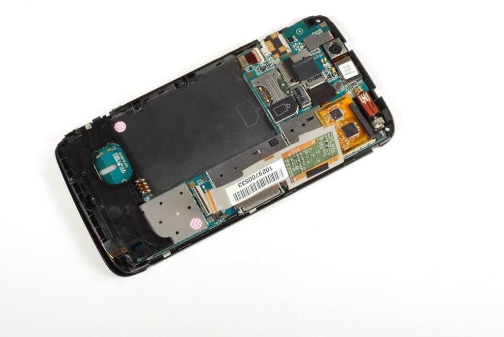
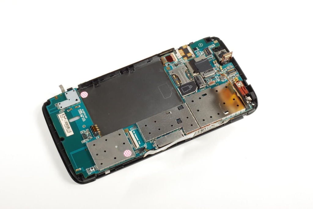
With the rear case completely removed, we get our first look inside the Dell Streak. While the 5 megapixel camera is clearly visible at the top of the device, most of the main PCB and chips are hidden. We’ll need to remove the main PCB for a better look at the Streak’s hardware.
Photo credit: Bill Detwiler / TechRepublic
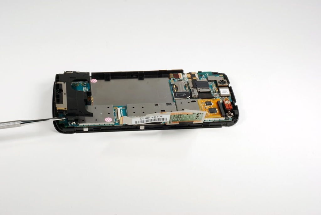
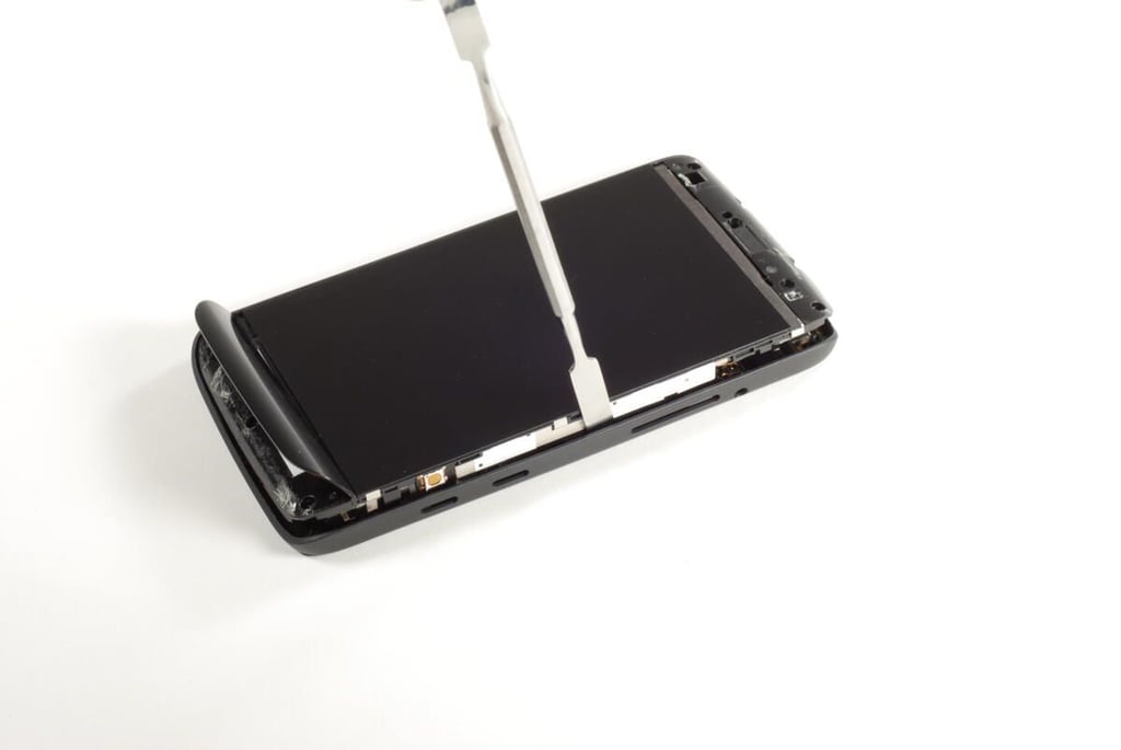
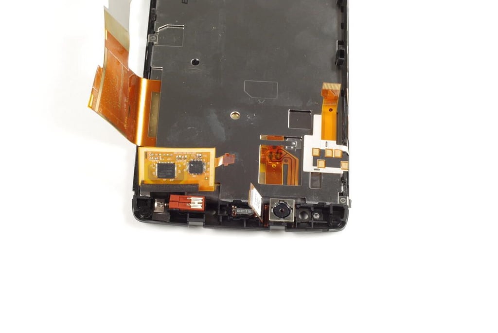
There is a small plastic bezel attached to the bottom of the main PCB and front panel assembly. You should be able to pry this loose using a thin metal blade or plastic spludger.
Photo credit: Bill Detwiler / TechRepublic
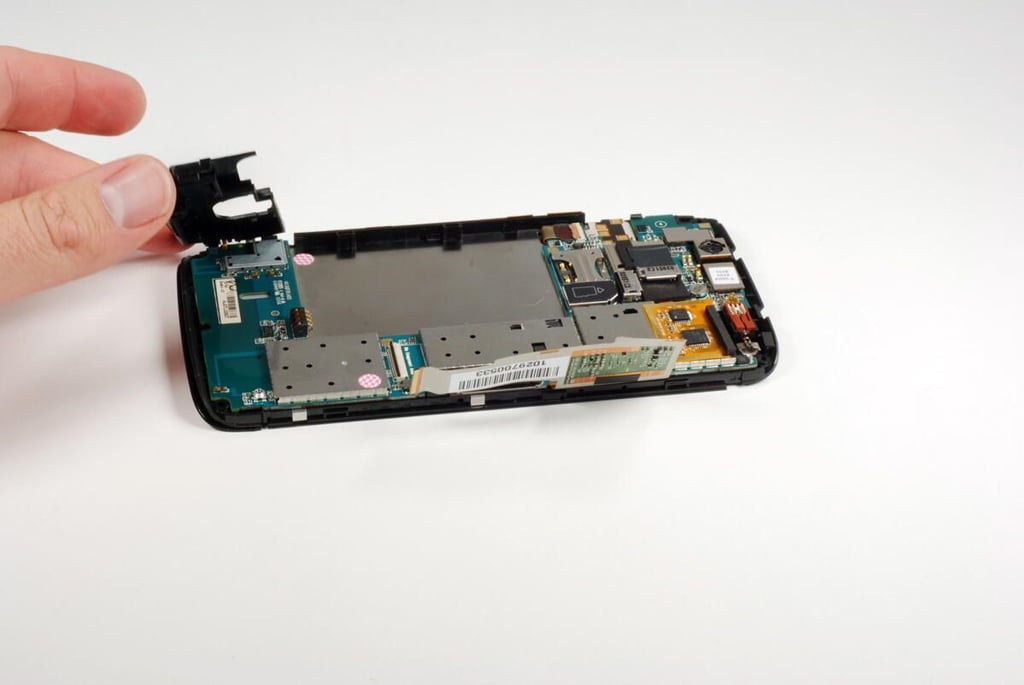
Photo credit: Bill Detwiler / TechRepublic
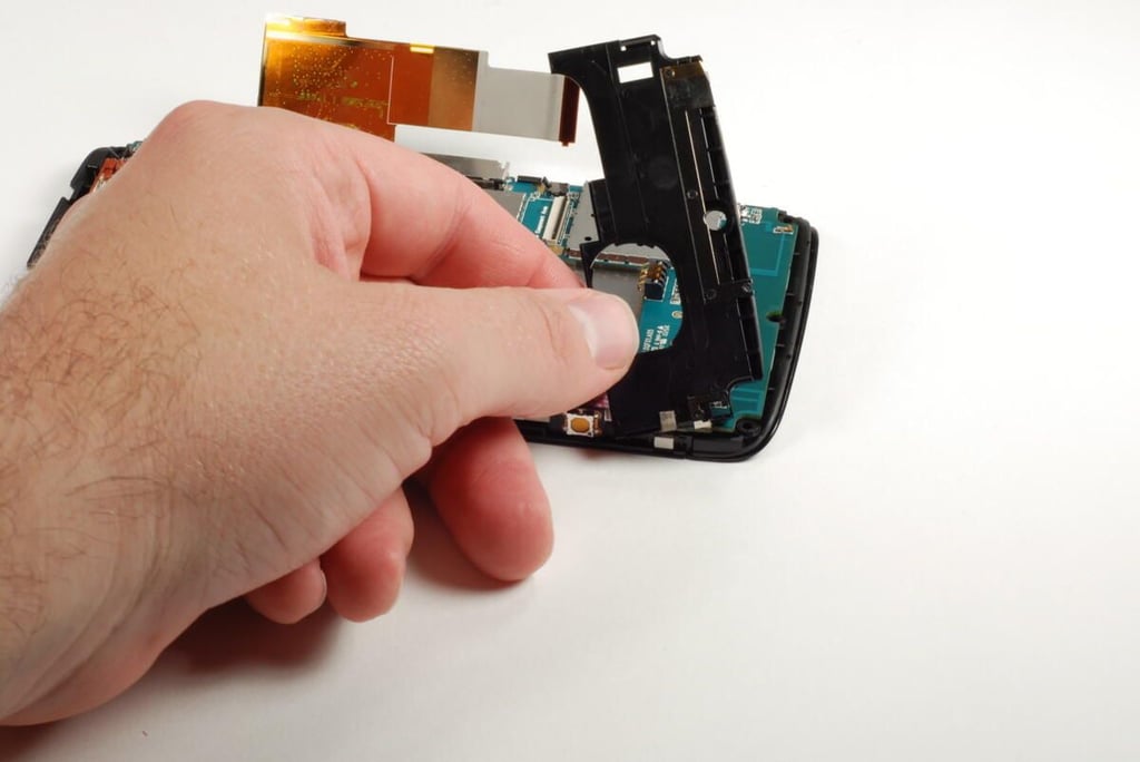
This thin metal strip is attached to the internal plastic bezel with a bit of weak adhesive. You should be able to pry the strip loose from the bezel without harming either component.
Photo credit: Bill Detwiler / TechRepublic
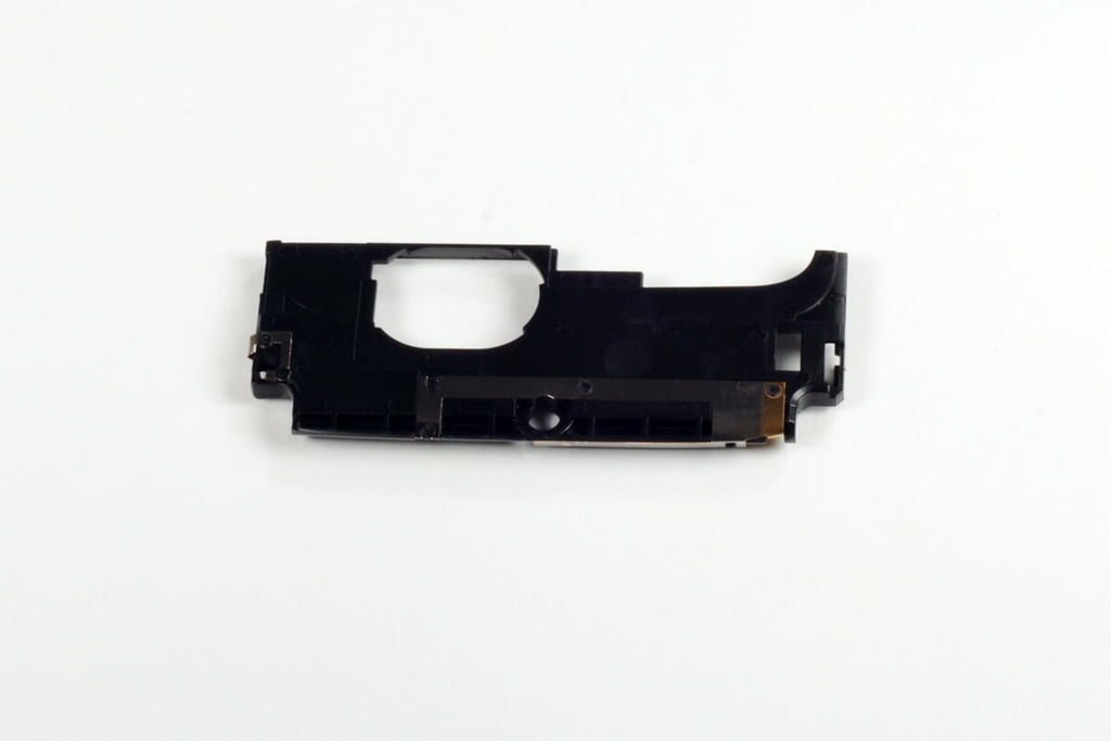
Photo credit: Bill Detwiler / TechRepublic
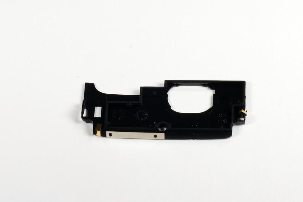
Photo credit: Bill Detwiler / TechRepublic
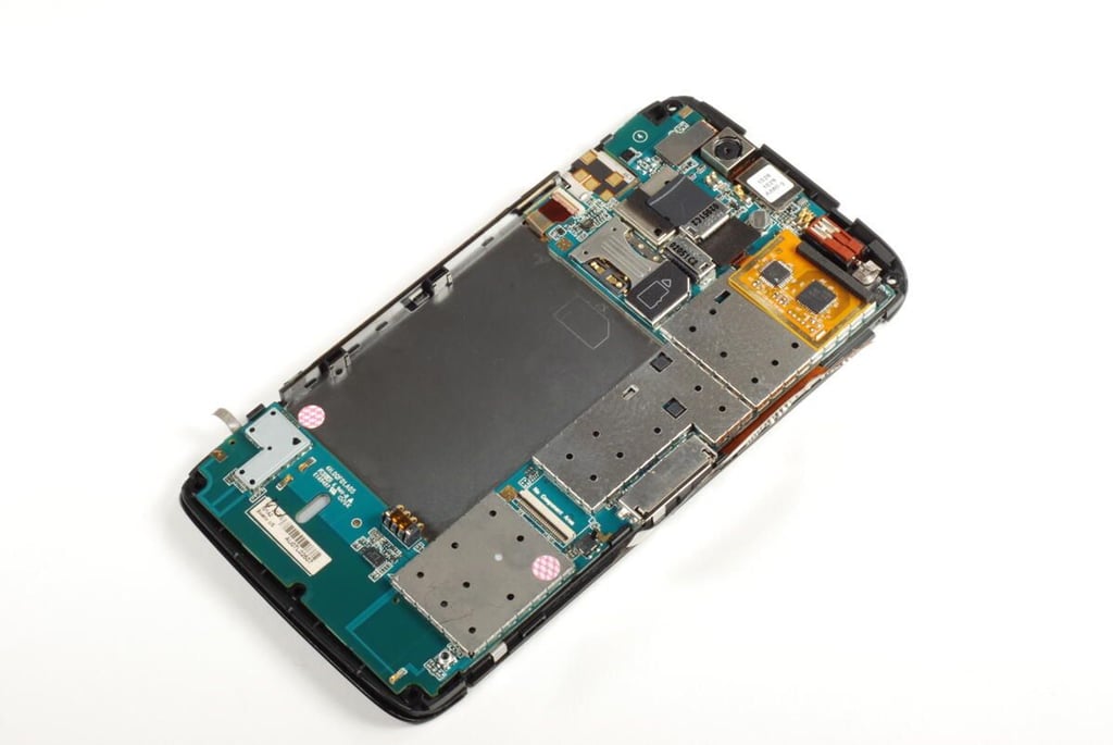
Photo credit: Bill Detwiler / TechRepublic
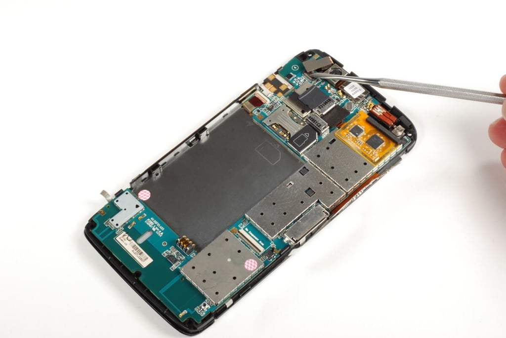
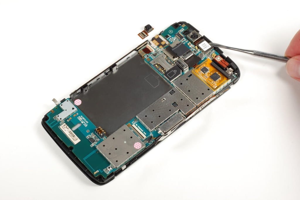
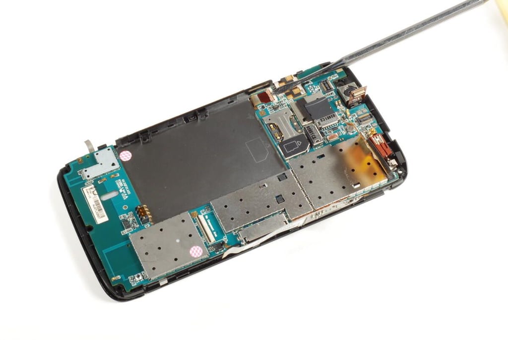
Before removing the main PCB from the front panel assembly, we must remove the various component connectors. We’ll start with the connector for the front-facing camera.
Photo credit: Bill Detwiler / TechRepublic
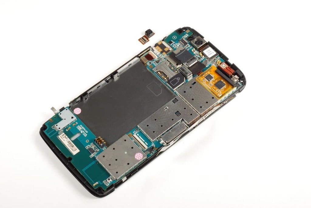
When disconnected from the main PCB, the front-facing camera can be pulled away from the front panel assembly.
Photo credit: Bill Detwiler / TechRepublic
The Dell Streak has a VGA front-facing camera.
Photo credit: Bill Detwiler / TechRepublic
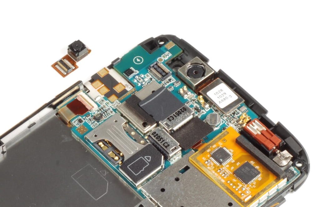
Next, we’ll disconnect the Dell Streak’s 5.0 megapixel, rear-facing camera from the main PCB.
Photo credit: Bill Detwiler / TechRepublic
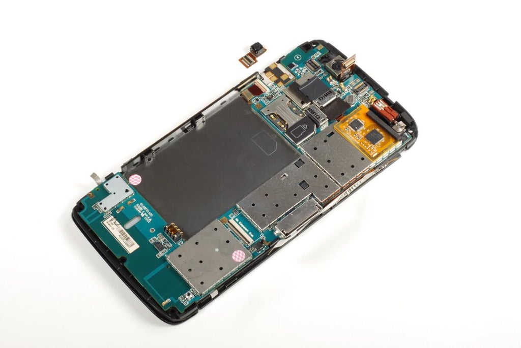
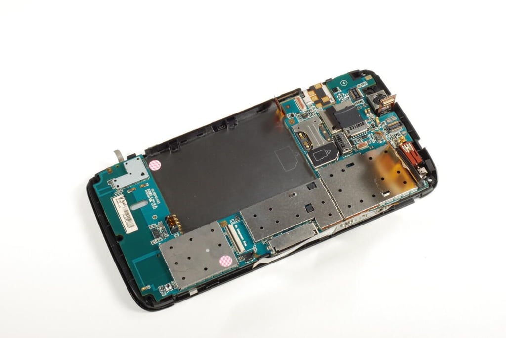
After disconnecting both camera connectors, we’ll turn our attention to the touchscreen connector and control button connector.
Photo credit: Bill Detwiler / TechRepublic
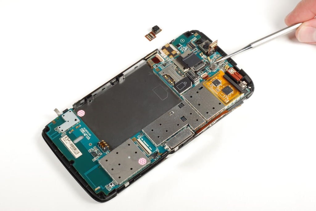
The main PCB connector for the touchscreen is located under a square, rubber cushion located directly below the rear-facing camera’s connector. There are two chips located on the touchscreen connector–the Pixcir Tango S32 Capacitive Touch Controller IC and Atmel ATmega168P 8-bit AVR microcontroller.
Photo credit: Bill Detwiler / TechRepublic
Gently lift up the gate on the connector and pull the ribbon cable away from the main PCB.
Photo credit: Bill Detwiler / TechRepublic
The touchscreen’s ribbon cable is attached to the metal shield beneath it with a small amount of adhesive. It may take a bit of effort, but you should be able to separate the cable from the shield without damaging the cable or the circuits connected to it.
Photo credit: Bill Detwiler / TechRepublic
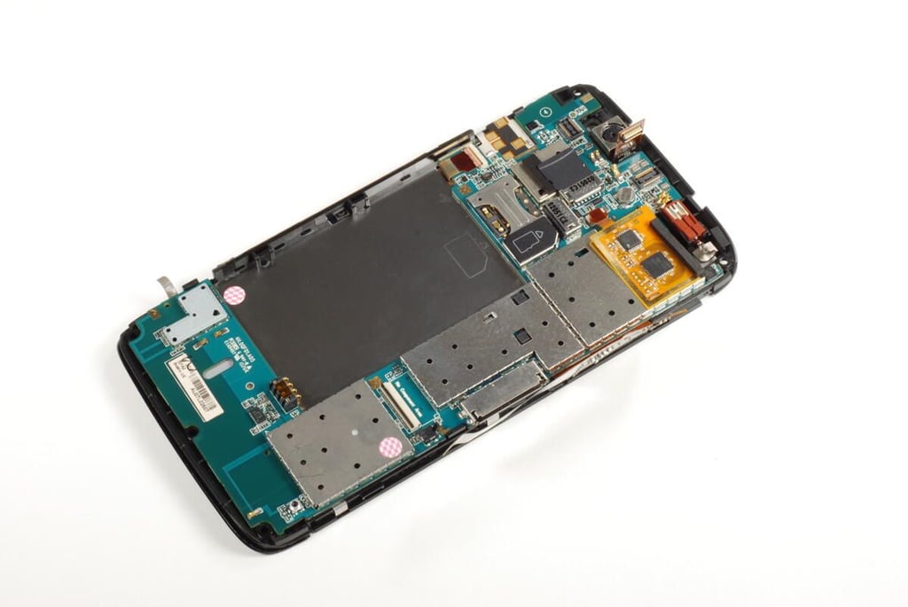
Lastly, disconnect the cable for the Dell Streak’s control buttons from the main PCB.
Photo credit: Bill Detwiler / TechRepublic
With all the connections removed, we’re ready to lift the main PCB away from the Dell Streak’s front panel assembly.
Photo credit: Bill Detwiler / TechRepublic
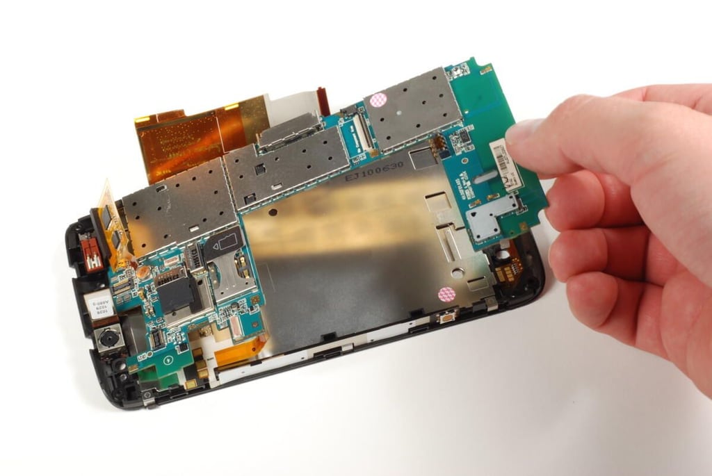
Photo credit: Bill Detwiler / TechRepublic
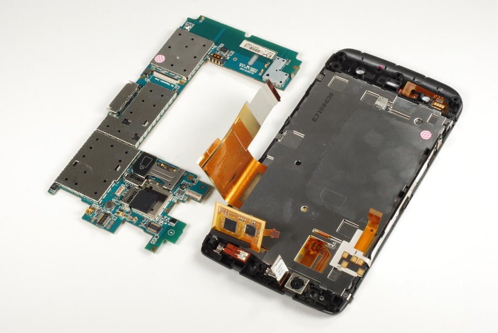
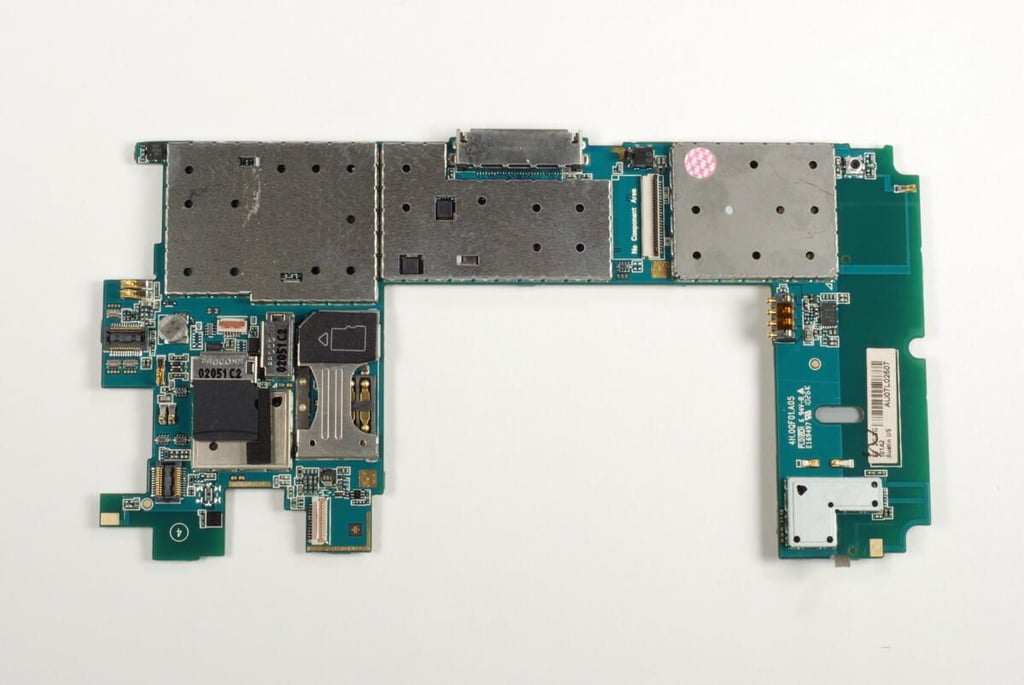
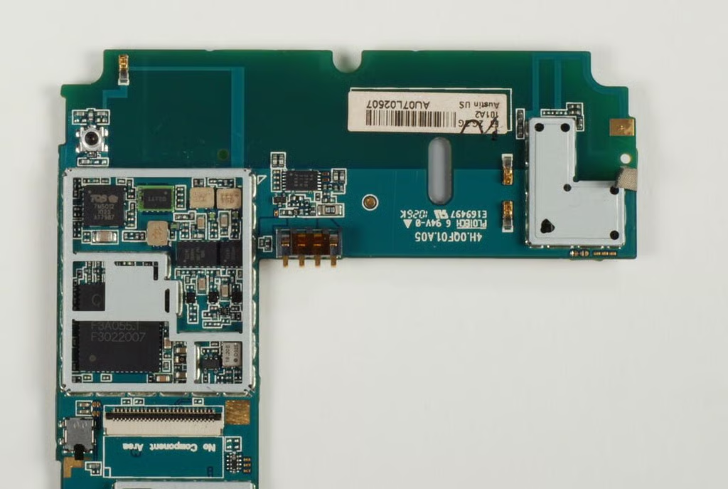
The Dell Streak’s c-shaped main PCB next to the front panel assembly.
Photo credit: Bill Detwiler / TechRepublic
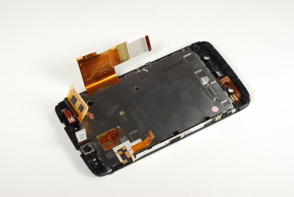
The Dell Streak’s LCD is permanently attached to the front panel’s Gorilla glass. You could pry the display and glass away from the front panel assembly, but they are joined with extremely strong adhesive and there’s really no reason to do so at this point as it would likely damage one or both of the components.
Photo credit: Bill Detwiler / TechRepublic
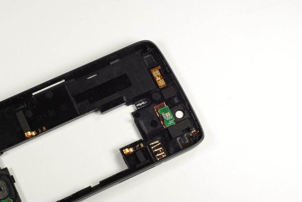
At the top of the front panel assembly is the rear-facing camera and most of the ribbon cables.
Photo credit: Bill Detwiler / TechRepublic
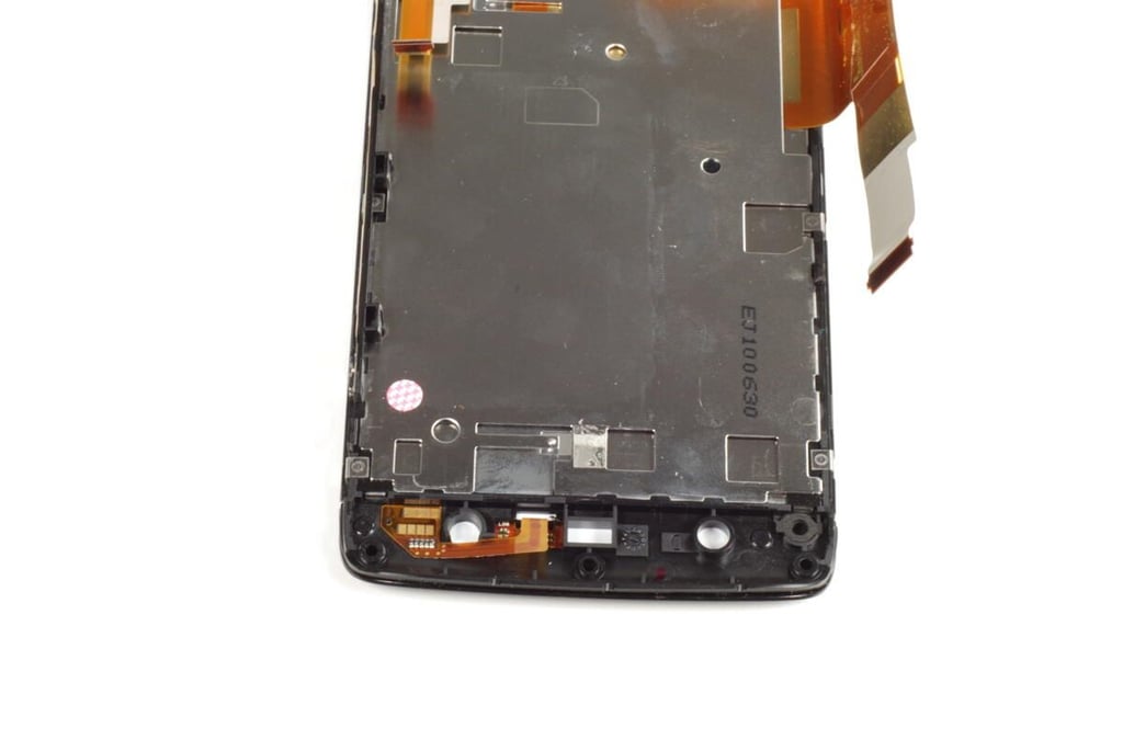
Photo credit: Bill Detwiler / TechRepublic
Nearly all of the chips on the Dell Streak’s main PCB are covered by thin metal shields. We’ll need to remove the shields to see the chips underneath.
Photo credit: Bill Detwiler / TechRepublic
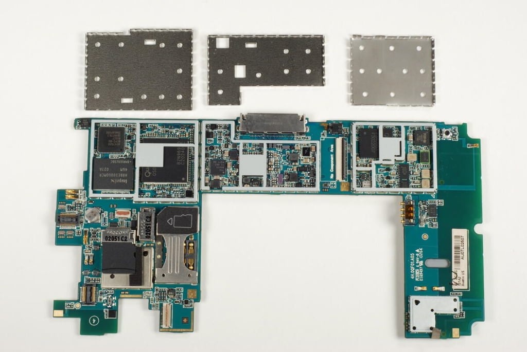
The three shields that cover most of the Dell Streak’s chips should pop off with a little effort.
Photo credit: Bill Detwiler / TechRepublic
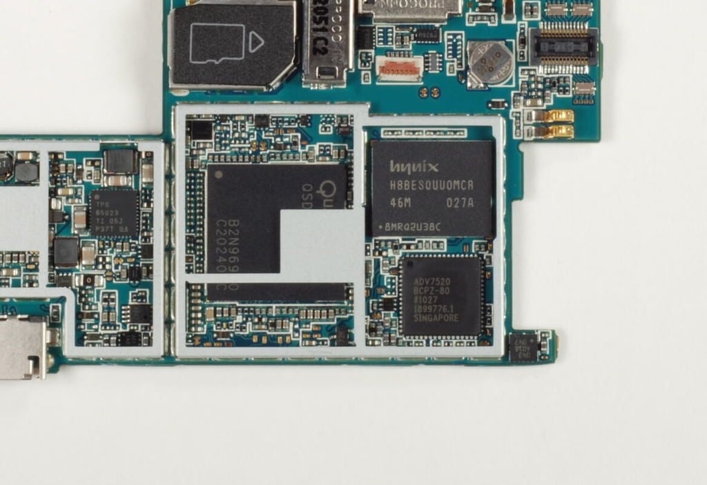
Under the first metal shield is the 1 GHz Qualcomm Snapdragon (QSD 8250) processor, Analog Devices Low Power HDMI/DVI Transmitter (ADV7520), and Hynix NAND-based MCP ( a combination of NAND Flash and mobile SDRAM – H8BES0UU0MCR).
Photo credit: Bill Detwiler / TechRepublic
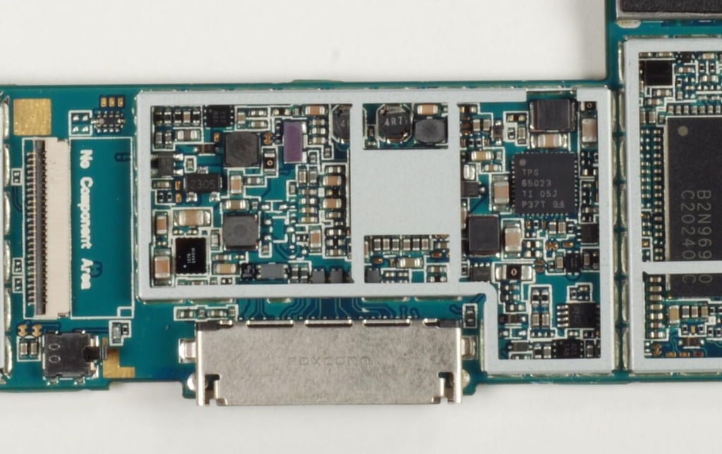
Under the center shield is the Texas Instruments TPS65023 Power Management IC for Li-ion-Powered Systems.
Photo credit: Bill Detwiler / TechRepublic
Under the last metal shield is another Qualcomm chip. A TriQuint Semiconductor TMQ7M5012 Quad-Band GSM/GPRS/EDGE-Polar Power Amplifier Module is located above it.
Photo credit: Bill Detwiler / TechRepublic
Bill Detwiler is the Editor for Technical Content and Ecosystem at Celonis. He is the former Editor in Chief of TechRepublic and previous host of TechRepublic's Dynamic Developer podcast and Cracking Open, CNET and TechRepublic's popular online show. Previously, Bill was an IT manager in the social research and energy industries. He has bachelor's and master's degrees from the University of Louisville, where he has also lectured on computer crime and crime prevention.


