Amiga1000Power’s RetroPC
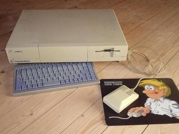
The finished system.
Submitted by Webshots member Amiga1000Power
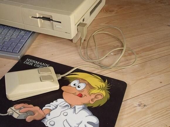
Mouse connection
Look at the Amiga 1000 mouse connected to the PC and working.
Submitted by Webshots member Amiga1000Power
Expansion port
View of the expansion port on the Amiga case now used as cooling air intake.
Submitted by Webshots member Amiga1000Power
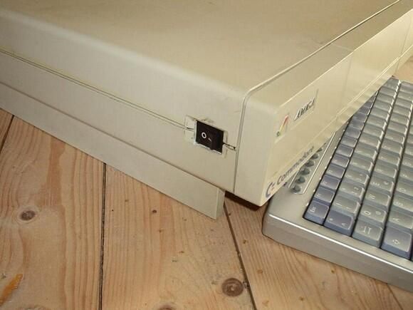
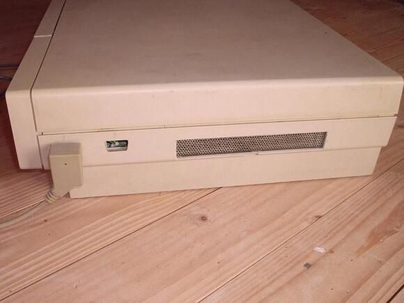
Power Switch
A look at the power switch used to switch on/off the power supply. The computer is started using a switch covered behind the Amiga symbol at the top, left edge of the front of the case.
Submitted by Webshots member Amiga1000Power
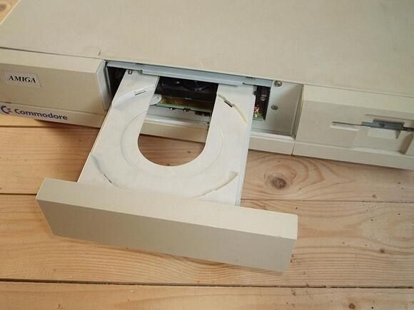
CDRW tray (2 of 2)
View to the opened CDRW tray and the front connectors below the CDRW-drive.
Submitted by Webshots member Amiga1000Power
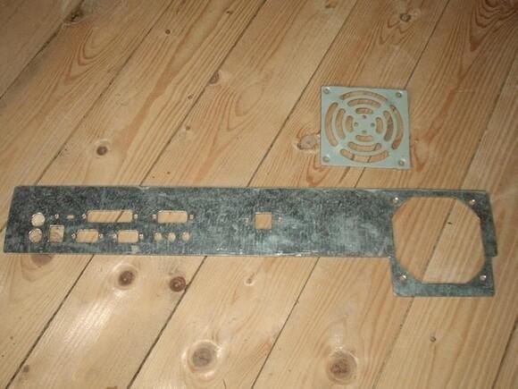
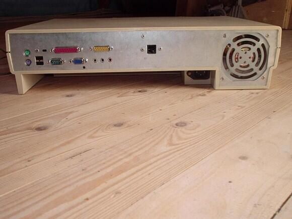
Amiga case – rear plate
This is new rear plate of the computer and the fence for the case fan.
Submitted by Webshots member Amiga1000Power
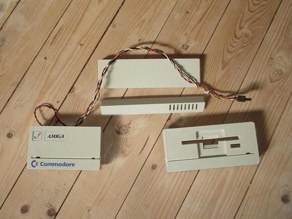
Amiga case – front parts – front view
The front view to the reworked front parts of the Amiga case. In the left part is added a HD-LED and the power-on switch covered by the Amiga symbol.
Submitted by Webshots member Amiga1000Power
Amiga case – front parts – rear view
The rear view of the reworked front parts of the Amiga case.
Submitted by Webshots member Amiga1000Power
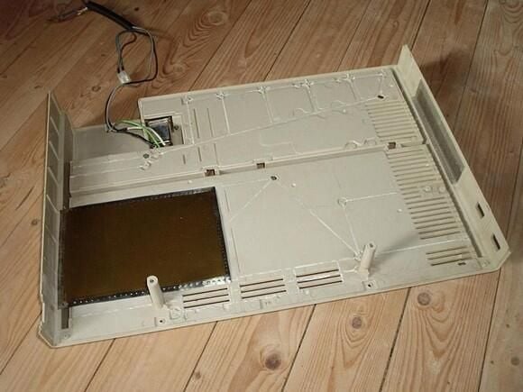
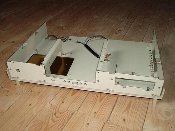
Amiga case – lower part
Here you see the reworked lower part of the Amiga case. At the right you can see the fence over the expansion port–now used as cooling air intake. At the right you see the (golden) shielding plate for the hard disk. This is a very thin plate, otherwise the hard disk wouldn’t fit into the case. At the rear is the power connector of the computer.
Submitted by Webshots member Amiga1000Power
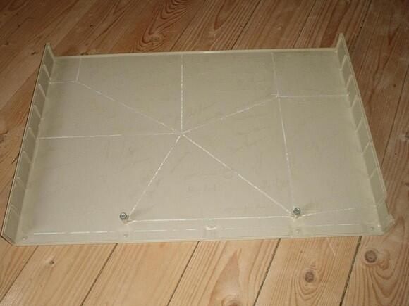
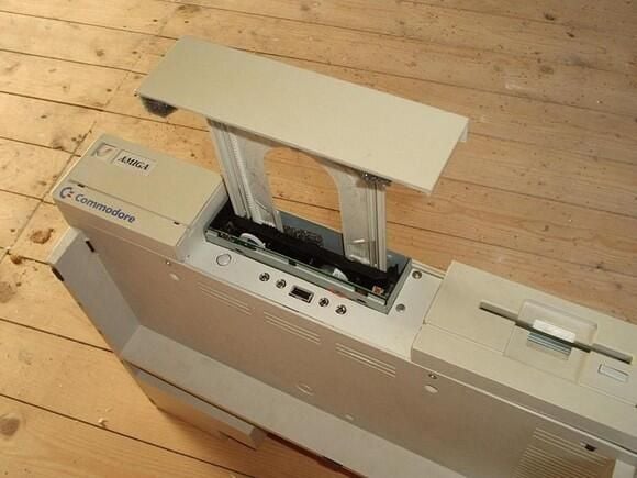
Amiga case – top cover
The reworked top cover, the signatures of the Amiga developers are still visible, only the rips are cut off.
Submitted by Webshots member Amiga1000Power
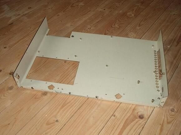
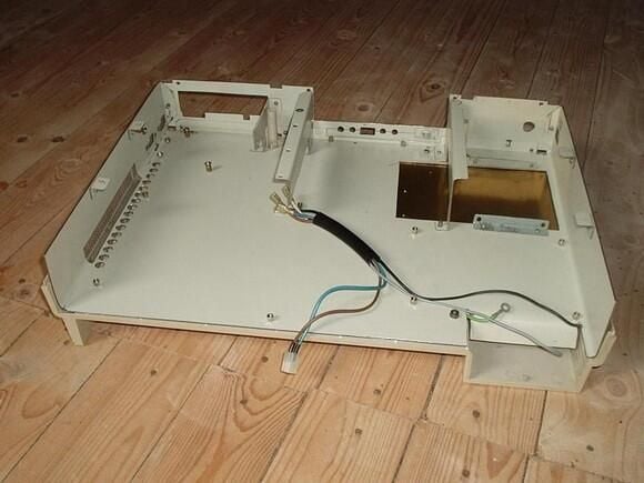
Inner case – lower part
This is the lower part of the inner case. Here you can see the cut-out for the HD at the left side and the air intake at the right side: A large hole for the expansion port and a couple of small holes for the original air intake in the bottom of the Amiga case.
Submitted by Webshots member Amiga1000Power
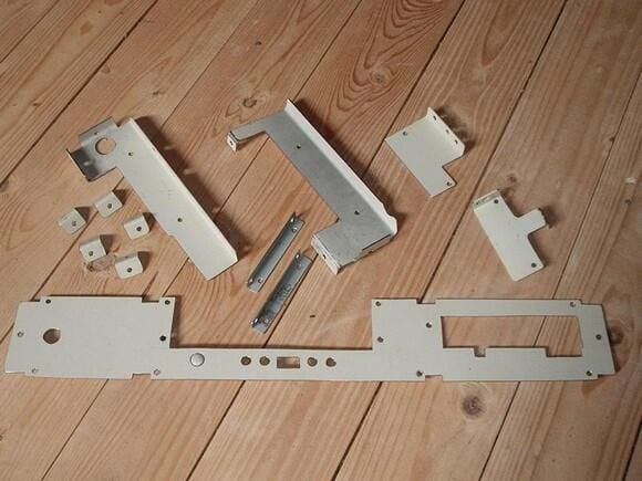
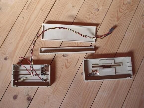
Inner case – front plate
This picture shows the front plate of the inner case with the cut-outs for the floppy drive, the CDRW, the front connectors and the cable of the new HD-LED and the power switch. The small plates are used to mount the drives in the case.
Submitted by Webshots member Amiga1000Power
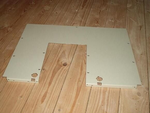
Inner case – top cover
This is the top cover of the inner case. The large cut-out is for the CDRW. IT would not fit into the Amiga case, if the CDRW would also be completely covered by this plate. A 3.5″ HD is 2.54 cm high, the CDRW has a height of about 4 cm and the Amiga case has an inner height of 6.5 cm. There is no space left if the CDRW is mounted on top of the HD.
Submitted by Webshots member Amiga1000Power
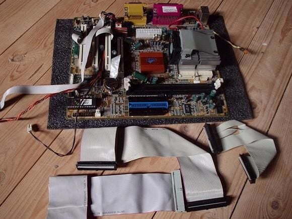
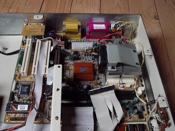
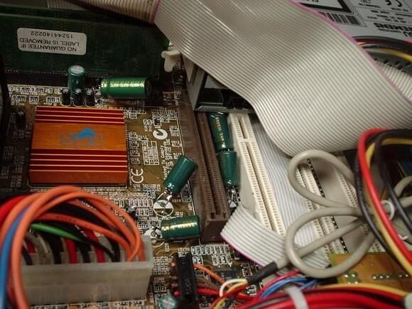
Motherboard cable
The motherboard and all cable modified for the use in this computer.
Submitted by Webshots member Amiga1000Power
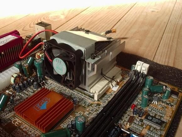
CPU-cooler (1 of 2)
The CPU-cooler is turned by 90 degrees so the air could flow from the right (the air intake through the expansion port) to the left of the case, where the fan at the rear blows the hot air out of the case. The CPU fan is also mounted vertical to suck the air through the cooler and blow it over the chipset-cooler to the left side of the case.
Submitted by Webshots member Amiga1000Power
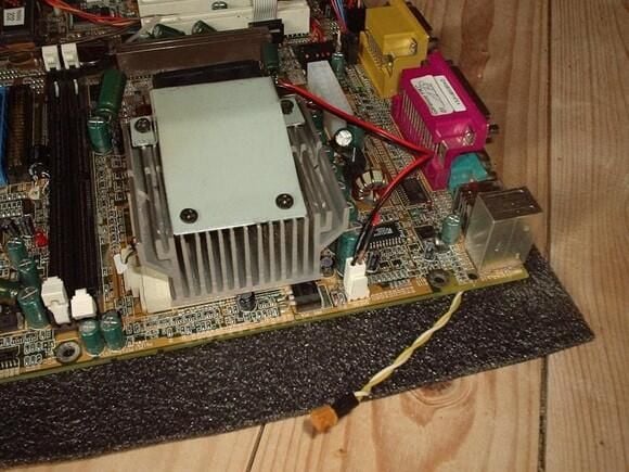
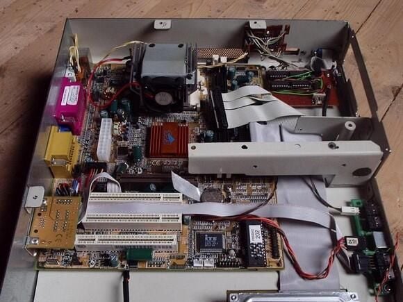
CPU-cooler (2 of 2)
An other view (from the expansion port) to the CPU cooler. You can also see the cable from the serial port that is connected to the additional logic used to attach an Amiga mouse to the original mouse port of the Amiga case.
Submitted by Webshots member Amiga1000Power
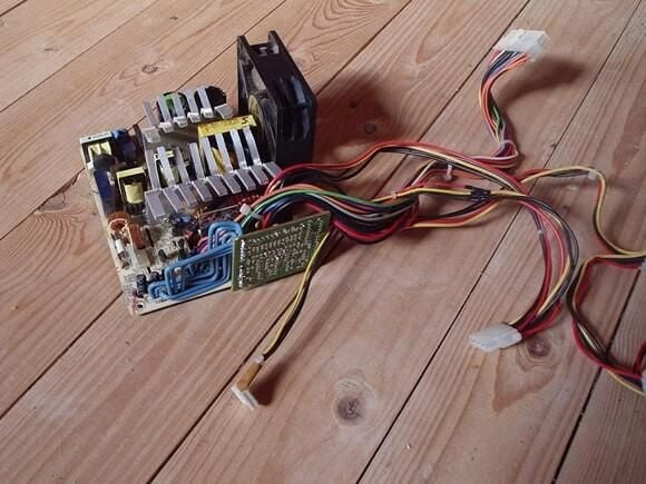
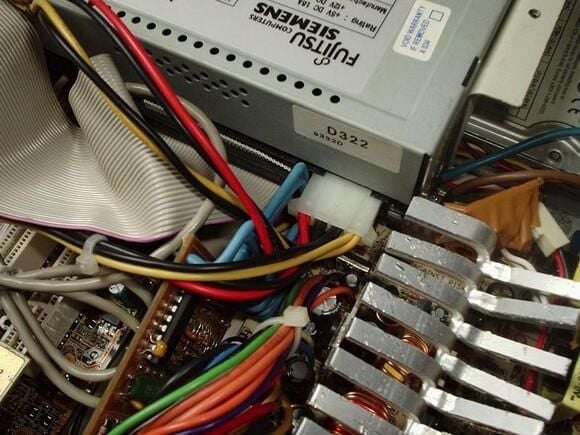
Power supply
Here you see the modified power supply for the computer. It is an ATX power supply removed from its case. The cooler are bend and the small PCB is turned by 90 degrees — using new (blue) wires to connect it. The power supply must have a maximum height of 6 cm to fit into the case.
Submitted by Webshots member Amiga1000Power
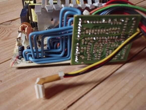
Power supply modifications
A closer look to the turned PCB and the accordingly bend wires. In front you see a modified connector for the floppy drive. You will see later why it was necessary to modify it.
Submitted by Webshots member Amiga1000Power
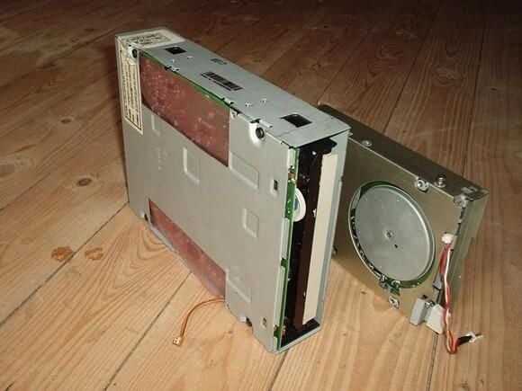
CDRW and floppy
The CDRW has to be modified. First the switch to open the tray has moved to another location (in the front plate of the inner case just below the drive). Second I had to cut-out an edge of the case of the drive to gain 2 mm space, otherwise the HD hasn’t fitted below the CDRW. The floppy drive has a modified knob and a cable to the LED in the front plate of the case.
Submitted by Webshots member Amiga1000Power
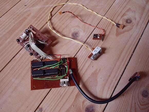
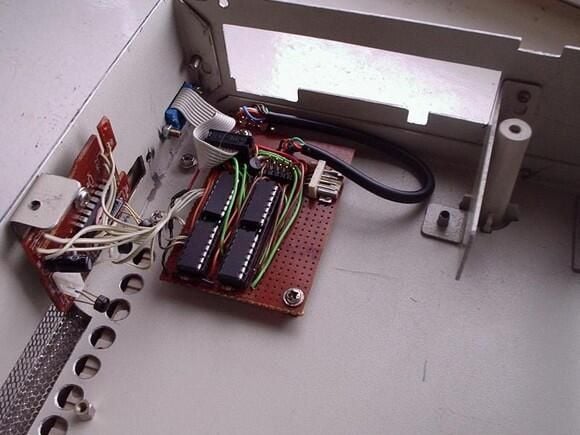
Additional logic circuits
Here you see the additional PCB’s with the logic used to attach an Amiga mouse to the PC’s serial port. The two small parts with the wires are just switches to disable the mouse port and to switch between an Amiga mouse connected to the port or a PC serial mouse. The smaller PCB is taken from a serial mouse and is used to interpret the mouse signals of the Amiga mouse and convert them to the signals of a serial mouse. The larger PCB is an electronic switch to bypass the logic if a PC serial mouse is connected instead of an Amiga mouse.
Submitted by Webshots member Amiga1000Power
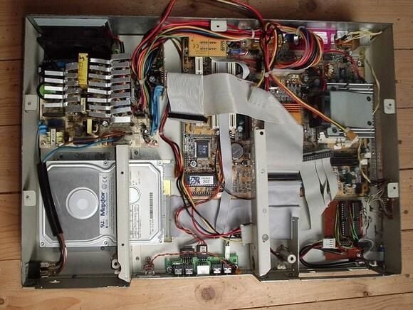
Assemble case – front view
This is the assembled inner case except the rear plate and the top cover.
Submitted by Webshots member Amiga1000Power
Assemble case – rear view
A rear view of the assembled case.
Submitted by Webshots member Amiga1000Power
Assemble mouse port
At the right of the case just below the floppy drive is the mouse port of the case. The vertical mounted PCB is the mouse logic, the horizontal mounted PCB is the electronic switch.
Submitted by Webshots member Amiga1000Power
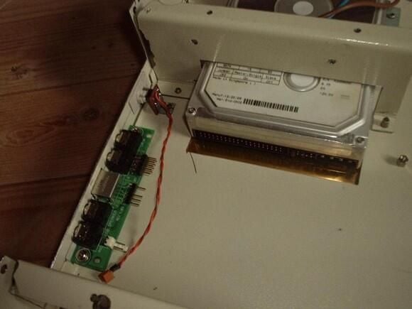
Mount hard disk
One of the first items that has to be mounted into the case is the hard disk. I hope that I never need to replace it because in that case I need to remove everything from the case before I could remove the hard disk.
Submitted by Webshots member Amiga1000Power
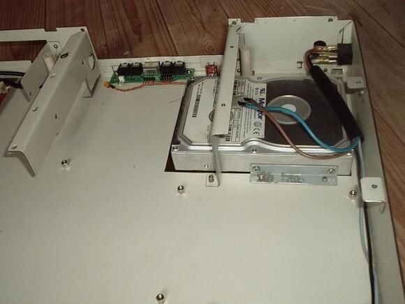
Mount front connectors
A closer view to the PCB with the front connectors and the new switch (with the wire) to open the tray of the CDRW.
Submitted by Webshots member Amiga1000Power
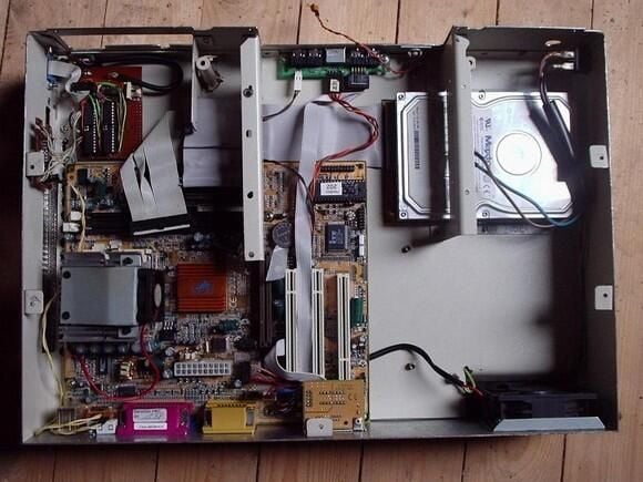
Mount motherboard (1 of 3)
Top view to the mounted motherboard.
Submitted by Webshots member Amiga1000Power
Mount motherboard (2 of 3)
Front view to the mounted motherboard. The small PCB at the rear plate just above the left edge of the motherboard is an Ethernet port adapter for this Gigabyte board.
Submitted by Webshots member Amiga1000Power
Mount motherboard (3 of 3)
Just another view to the mounted motherboard.
Submitted by Webshots member Amiga1000Power
Mount power supply (1 of 2)
Now the power supply is mounted and connected to the motherboard and the hard disk.
Submitted by Webshots member Amiga1000Power
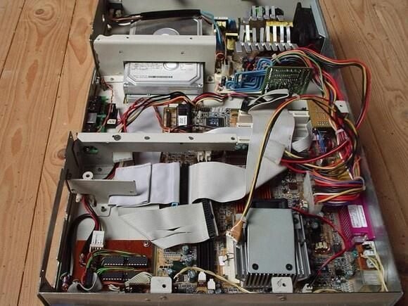
Mount power supply (2 of 2)
Another view to the mounted power supply.
Submitted by Webshots member Amiga1000Power
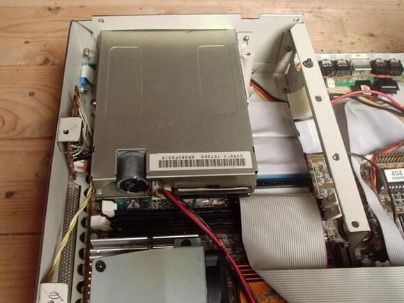
Mount floppy (1 of 2)
Now the floppy is fitted into the case.
Submitted by Webshots member Amiga1000Power
Mount floppy (2 of 2)
It is difficult to screw the floppy (there is an extra hole for the screwdriver in the mounting plate for the CDRW).
Submitted by Webshots member Amiga1000Power
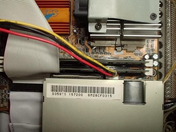
Mount Ram
There is just no space left between the rear of the floppy and the ram.
Submitted by Webshots member Amiga1000Power
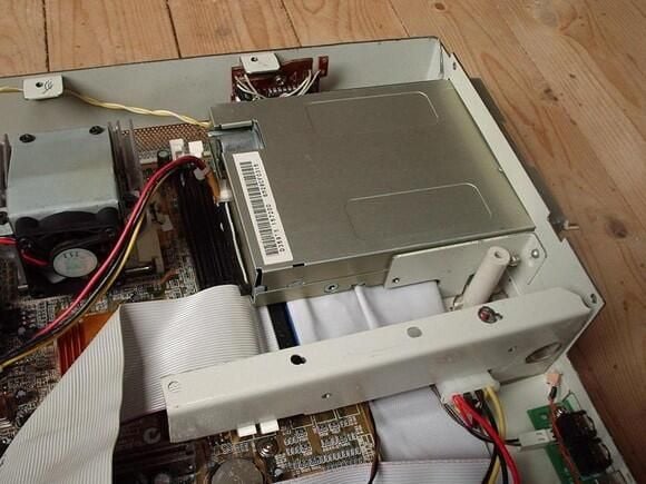
Mount CDRW (2 of 3)
The AGP port is covered by the drive and only one of the PCI ports may be used if the card is not longer than the port.
Submitted by Webshots member Amiga1000Power
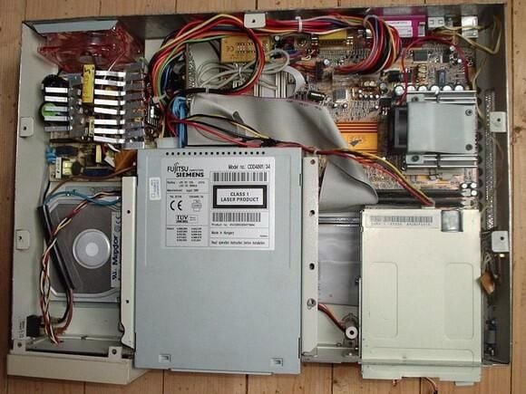
Mount CDRW (3 of 3)
The (blue) wires of the small PCB of the power supply just fit between the power connector and the IDE-cable of the CDRW.
Submitted by Webshots member Amiga1000Power
Bill Detwiler is the Editor for Technical Content and Ecosystem at Celonis. He is the former Editor in Chief of TechRepublic and previous host of TechRepublic's Dynamic Developer podcast and Cracking Open, CNET and TechRepublic's popular online show. Previously, Bill was an IT manager in the social research and energy industries. He has bachelor's and master's degrees from the University of Louisville, where he has also lectured on computer crime and crime prevention.


