TechRepublic’s Jason Hiner called the Samsung Focus the “first great Windows Phone 7 device.” Luckily, after Jason was finished reviewing the Focus, I got a chance to crack it open. Follow along as we see what hardware is hidden inside the Samsung Focus.
Photo by: Bill Detwiler / TechRepublic
Caption by: Bill Detwiler
The Samsung Focus runs Windows Phone 7 and is available from AT&T Wireless for $199 US (with a 2-year contract).
Photo by: Bill Detwiler / TechRepublic
Caption by: Bill Detwiler
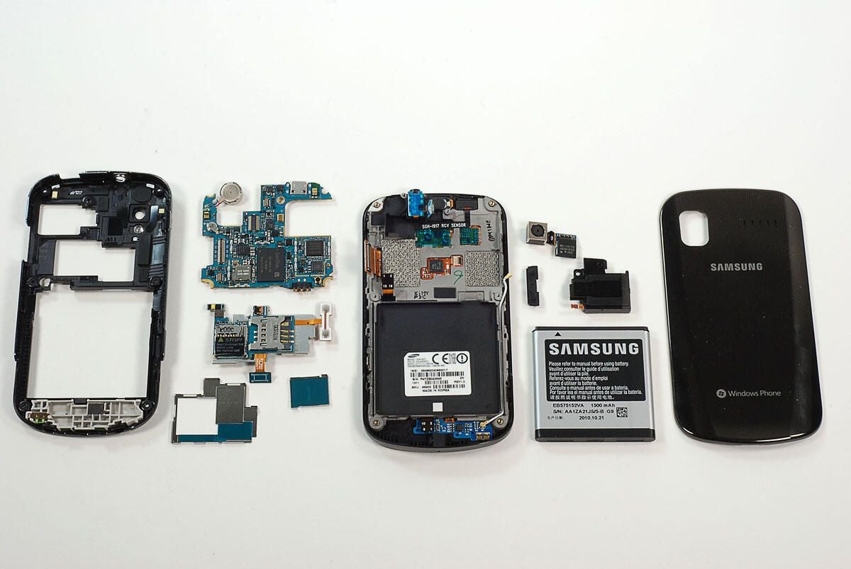
The Samsung Focus has a 1.0GHz Snapdragon QSD8250 processor, 512MB RAM, 8GB of on-board storage, a microSD slot, and a 4-inch touch-sensitive display.
Photo by: Bill Detwiler / TechRepublic
Caption by: Bill Detwiler
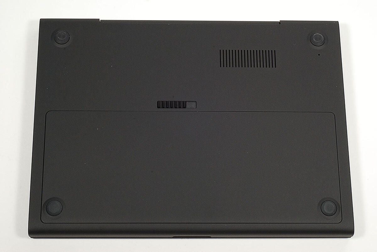
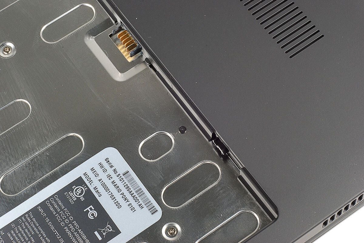
The first step in disassembling the Samsung Focus is removing the battery cover from the back of the phone. The Samsung focus has a 1500mAh Lithium-ion battery.
Photo by: Bill Detwiler / TechRepublic
Caption by: Bill Detwiler
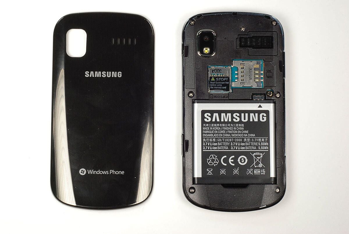
Photo by: Bill Detwiler / TechRepublic
Caption by: Bill Detwiler
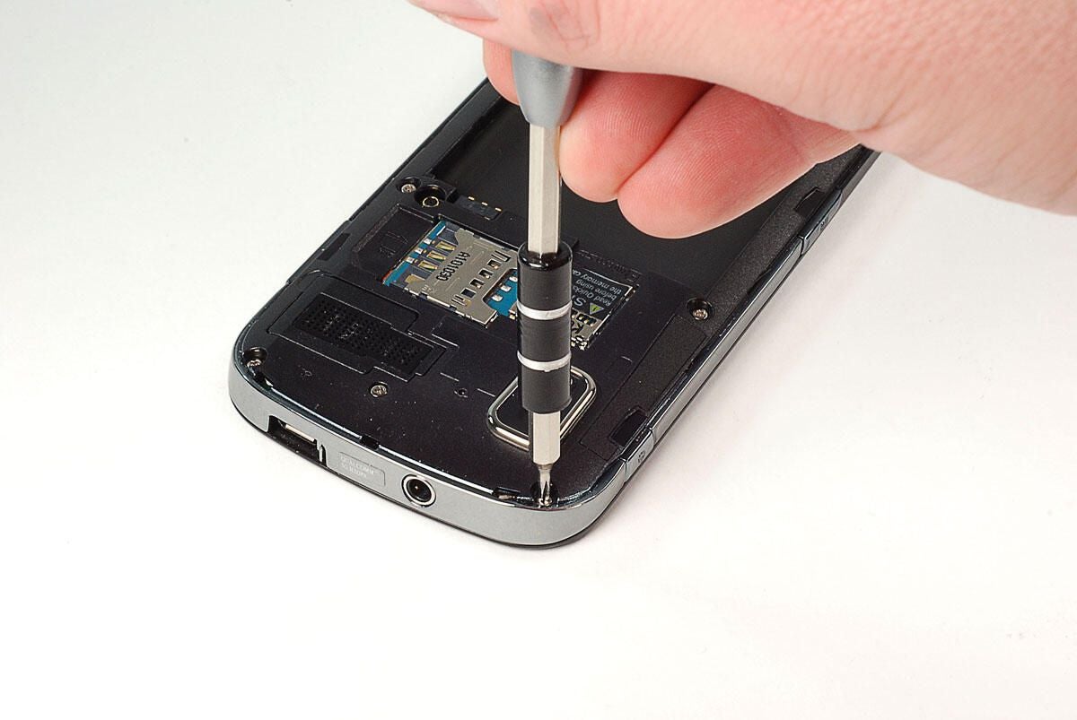
Luckily, Samsung used standard Phillips screws on the Focus’ case. I removed the seven screws with a Phillips #000 bit.
Photo by: Bill Detwiler / TechRepublic
Caption by: Bill Detwiler
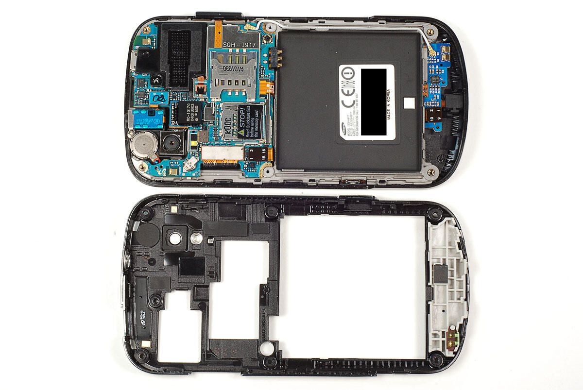
Once the seven external screws are removed, you can use a thin metal blade or plastic case opening tool to pop the back half of the case loose from the Samsung Focus. You should be able to gently work your way around the case without breaking at of the back half’s small plastic tabs.
Photo by: Bill Detwiler / TechRepublic
Caption by: Bill Detwiler
Photo by: Bill Detwiler / TechRepublic
Caption by: Bill Detwiler
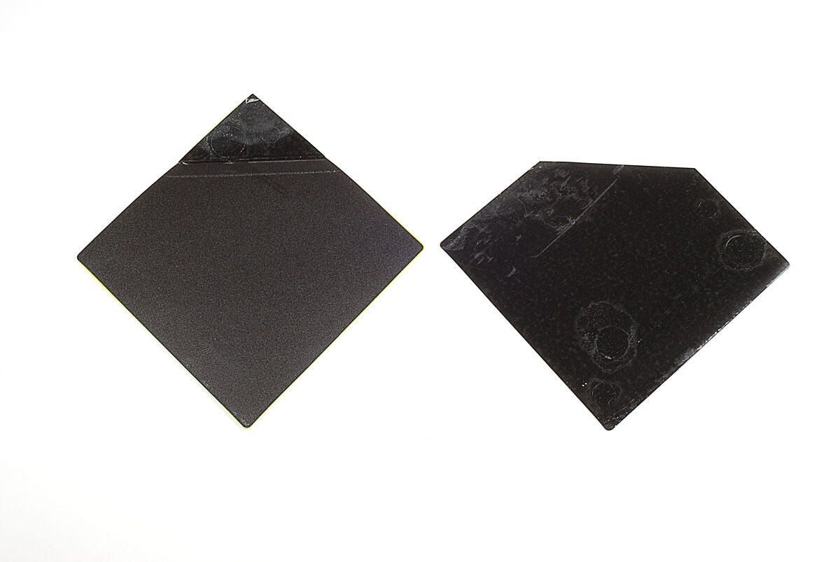
A small metal gasket is set within thin slots at the top of case. This gasket sits behind the hole in the case for the headphone jack. Take care when removing the back half of the case from the rest of the Samsung Focus as this gasket is not secured to the case.
Photo by: Bill Detwiler / TechRepublic
Caption by: Bill Detwiler
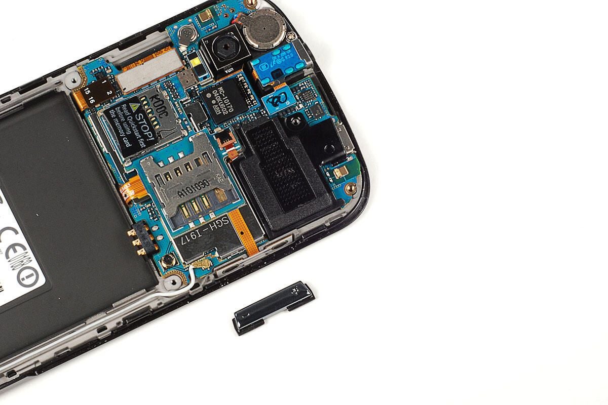
The Samsung Focus’ volume up/down button is not attached to either half of the case.
Photo by: Bill Detwiler / TechRepublic
Caption by: Bill Detwiler
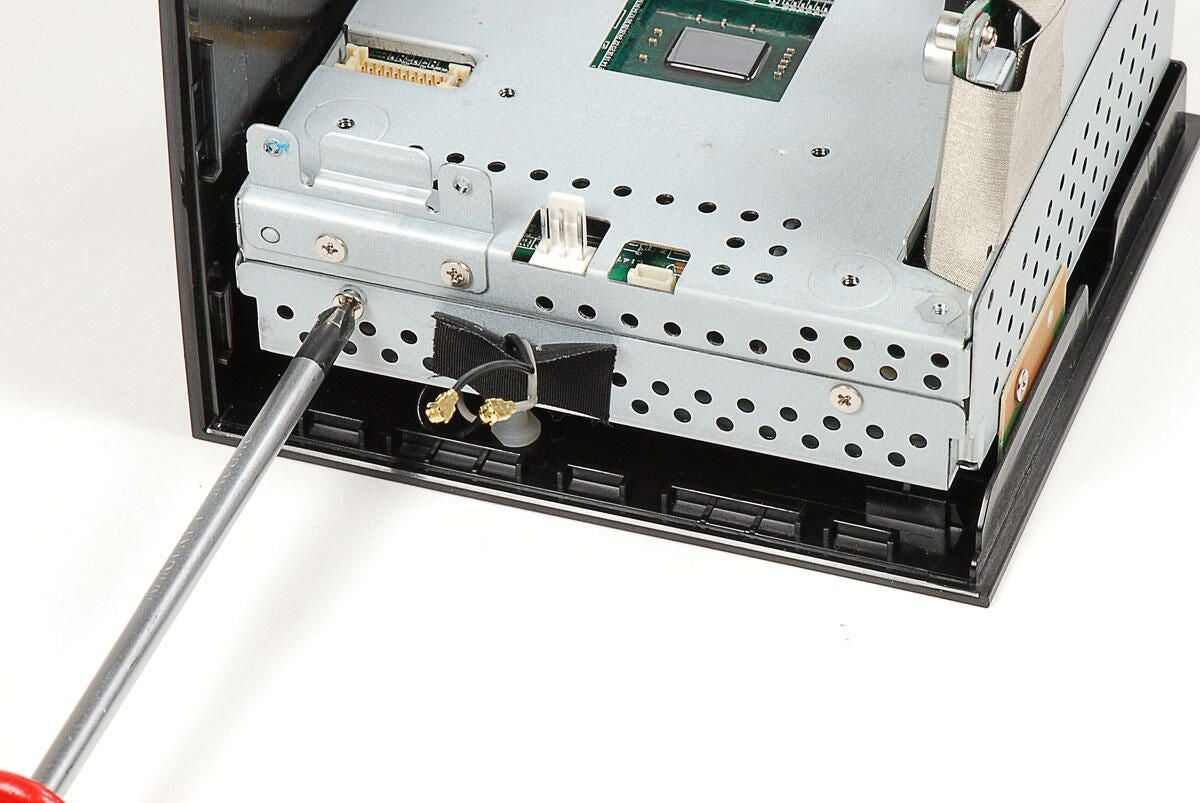
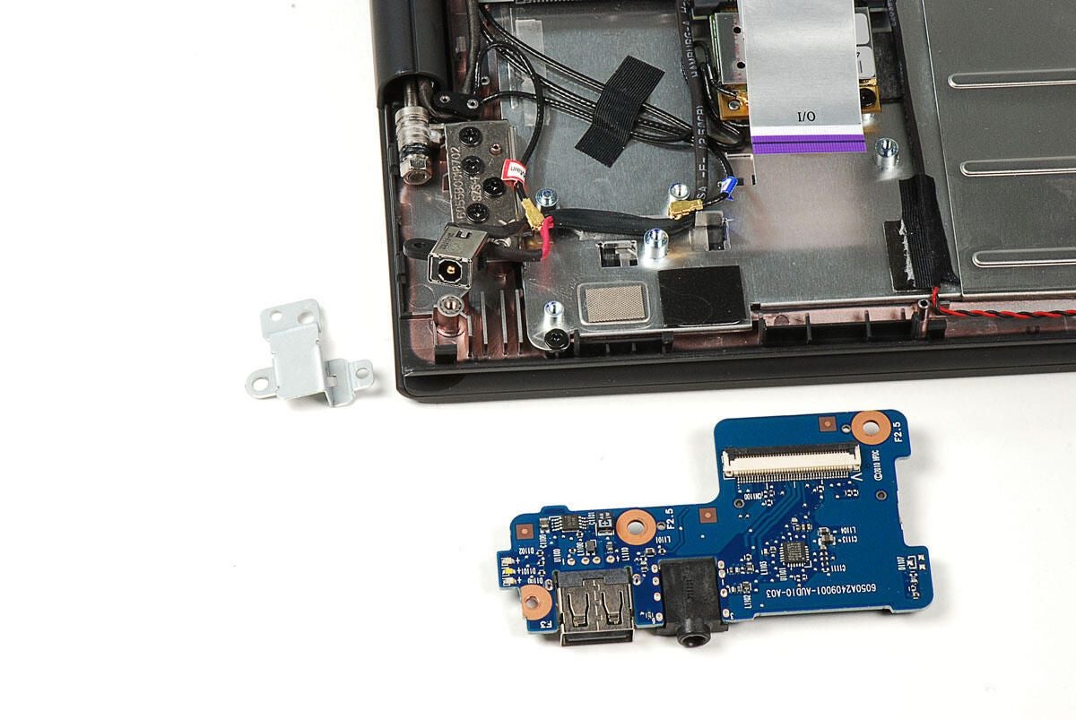
A thin metal bracket overlaps the Samsung Focus’ headphone jack. A single Phillips screws holds the bracket in place.
Photo by: Bill Detwiler / TechRepublic
Caption by: Bill Detwiler
Either after or before removing the headphone jack bracket, you’ll also need to pry loose its connector from the main PCB. The headpone jack appeared to be attached to the case with strong adhesive. As leaving it in place wouldn’t stop me from removing the main PCB, I decide not to pry it loose.
Photo by: Bill Detwiler / TechRepublic
Caption by: Bill Detwiler
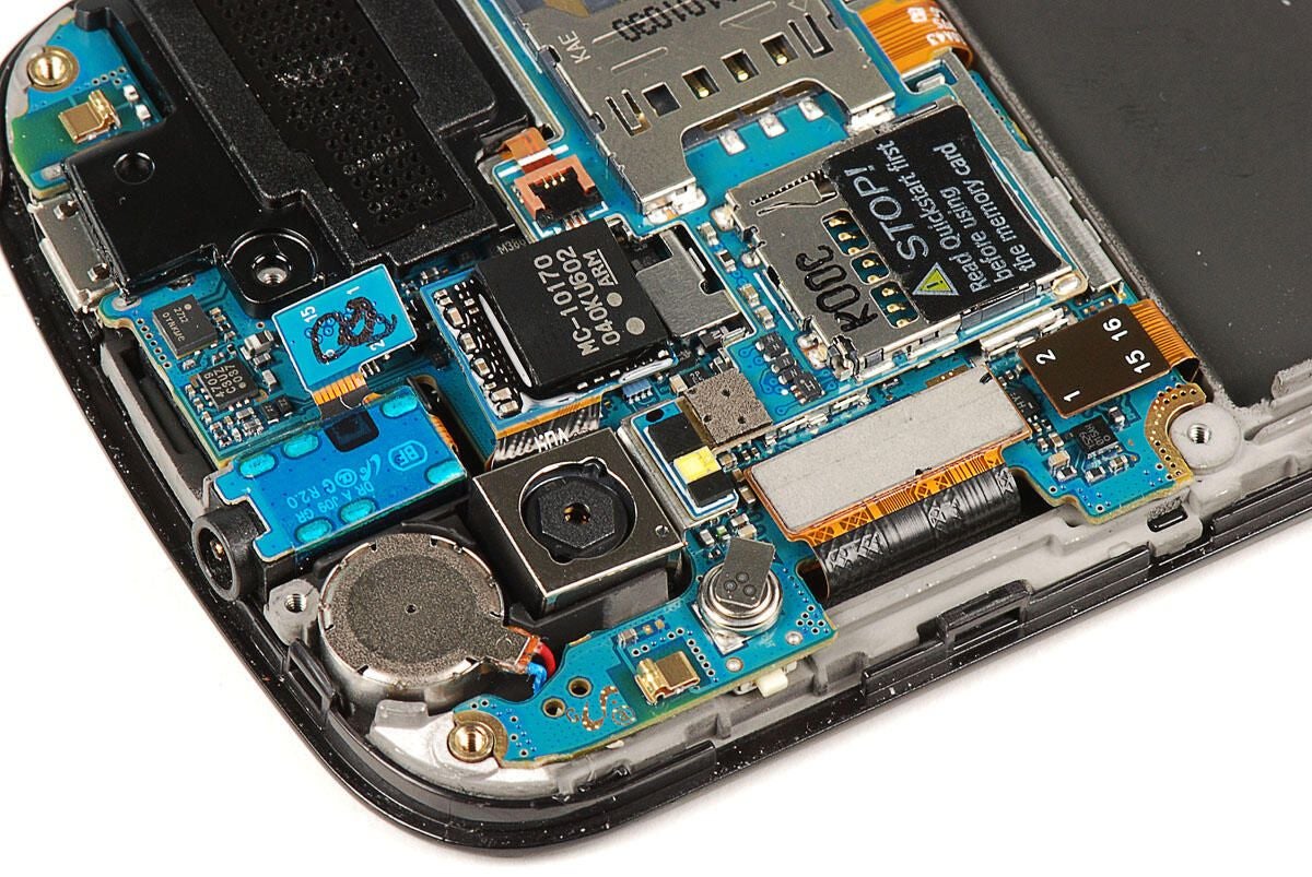
To remove the Samsung Focus’ 5.0MP camera you’ll need to pry loose its connector from the main PCB.
Photo by: Bill Detwiler / TechRepublic
Caption by: Bill Detwiler
With the camera disconnected from the main PCB, you can easily lift it out of the Samsung Focus.
Photo by: Bill Detwiler / TechRepublic
Caption by: Bill Detwiler
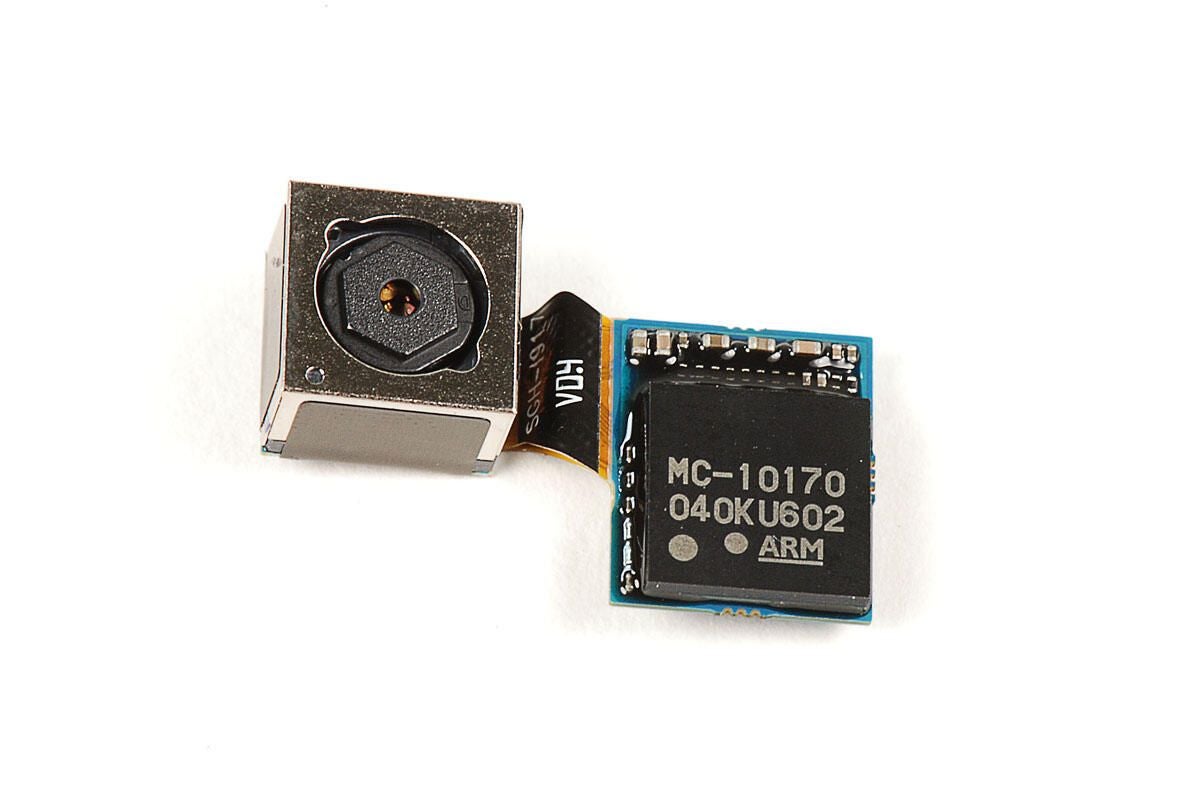
The Samsung Focus’ camera assembly uses the NEC MC-10170 image processor. This is the same IC used on the Samsung Galaxy S camera.?
Photo by: Bill Detwiler / TechRepublic
Caption by: Bill Detwiler
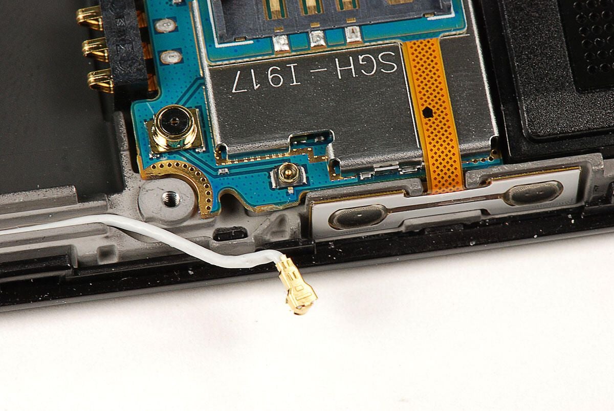
We’ll need to disconnect this antenna cable before removing the main PCB.
Photo by: Bill Detwiler / TechRepublic
Caption by: Bill Detwiler
Next, we’ll need to disconnect the three remaining cables attached to the Samsung Focus’ main PCB. The two large connectors (shown on the left) should pop loose without much force.
A much smaller ribbon cable (shown on the right) connects the speaker assembly to the small PCB that sit on top of the main PCB. To release the cable, gently lift up on the connector’s locking gate.
Photo by: Bill Detwiler / TechRepublic
Caption by: Bill Detwiler
With the ribbon cable disconnected, you can pry the speaker loose from the rest of the Samsung Focus. It’s not secured with adhesive, but it does fit very tightly.
Photo by: Bill Detwiler / TechRepublic
Caption by: Bill Detwiler
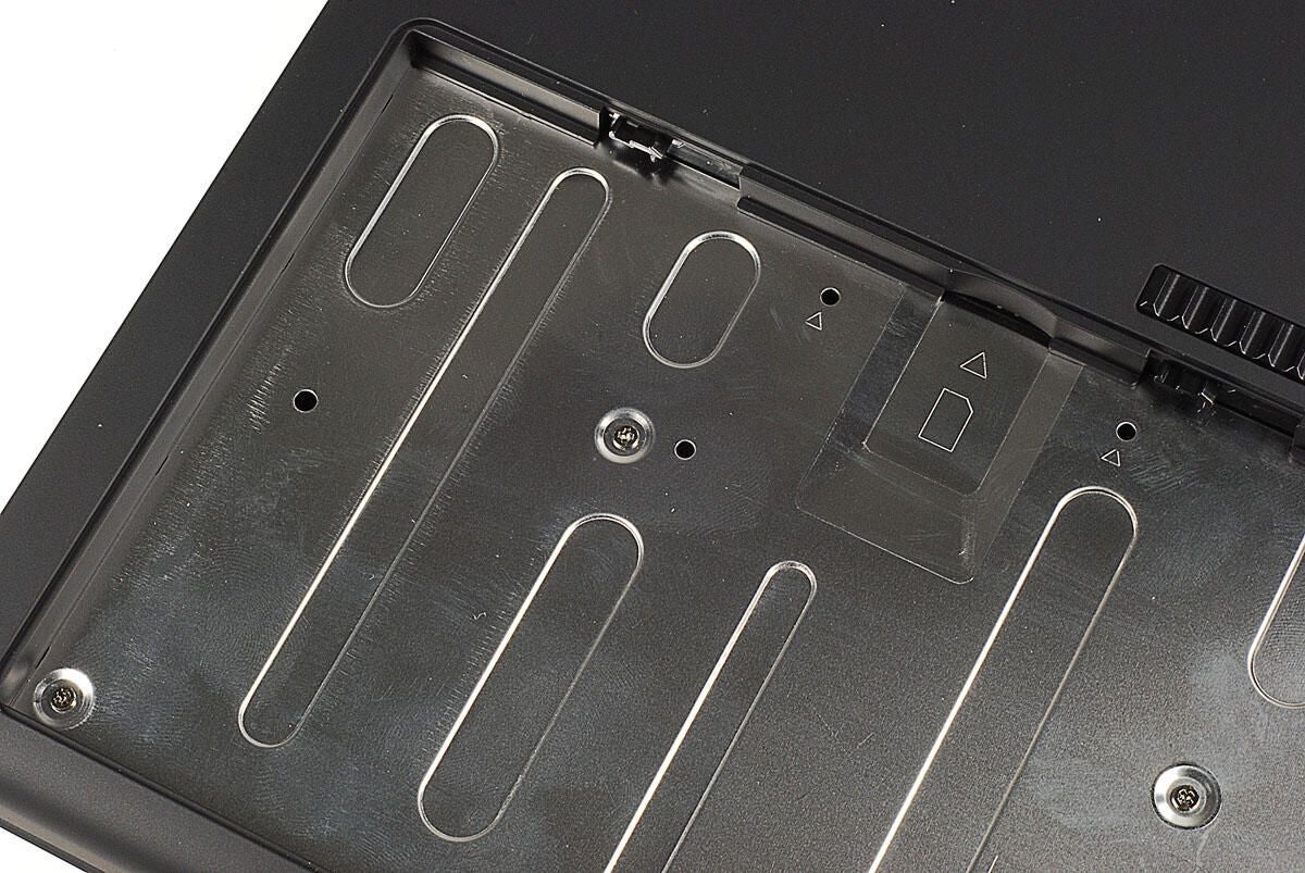
Photo by: Bill Detwiler / TechRepublic
Caption by: Bill Detwiler
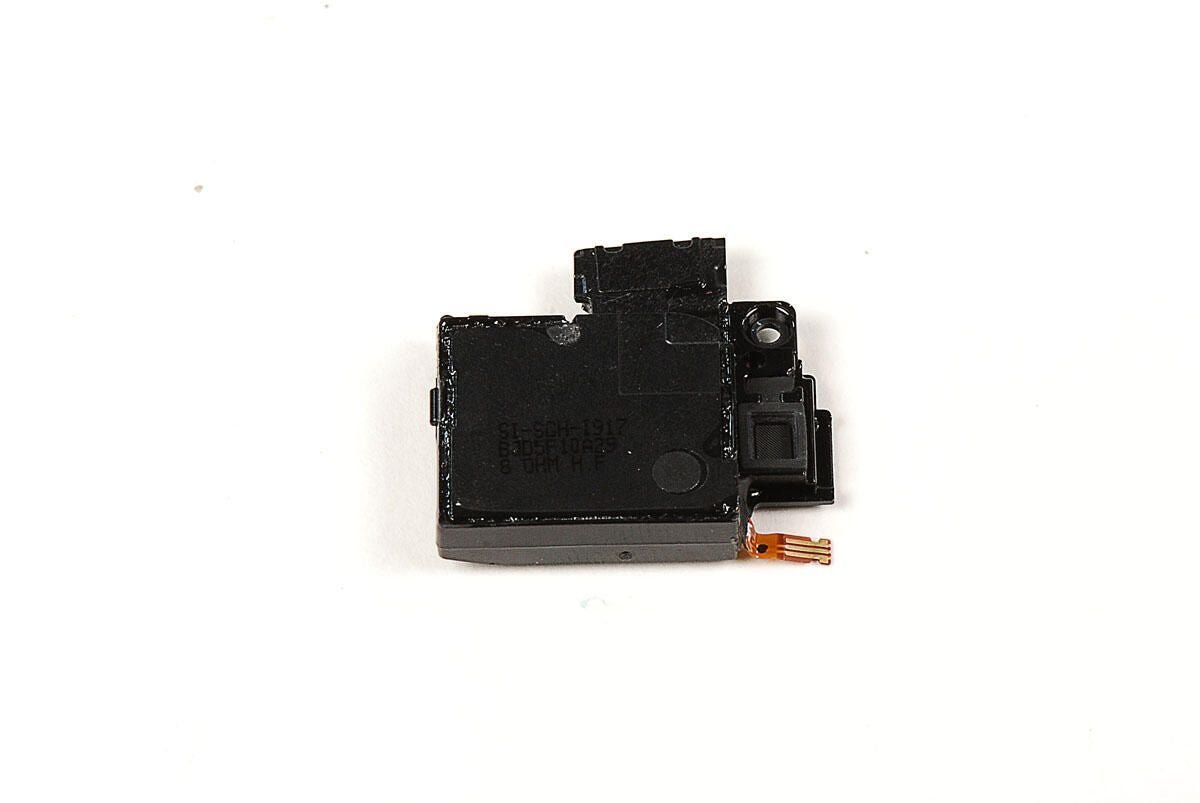
Photo by: Bill Detwiler / TechRepublic
Caption by: Bill Detwiler
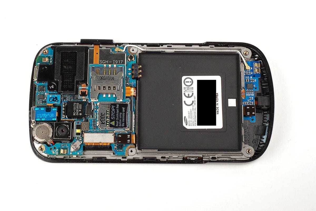
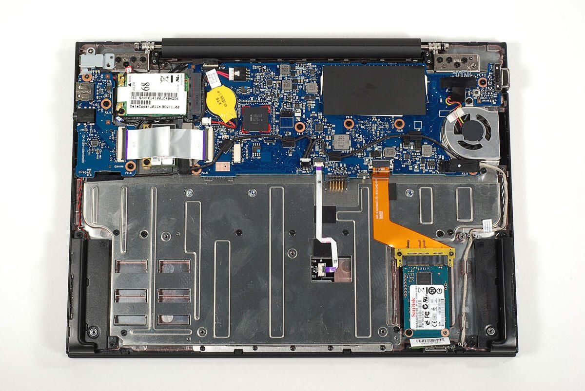
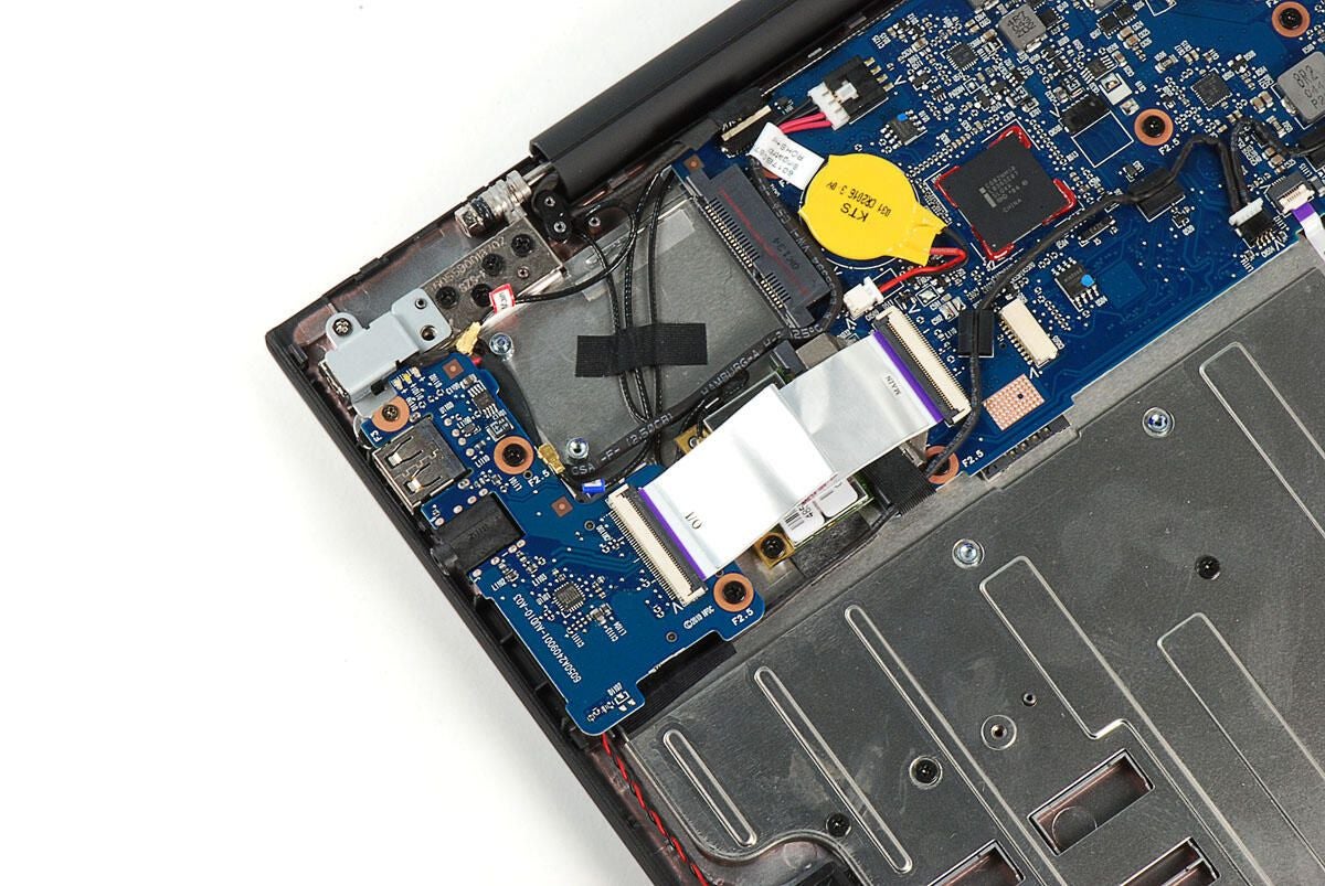
With all the cables disconnected, you can gently pry both the main PCB and smaller PCB (still attached to the main) away from the Samsung Focus. Take great care when doing this. As the next photo shows, the PCBs are still connected to the front case panel by the contacts for the volume up/down button.
Photo by: Bill Detwiler / TechRepublic
Caption by: Bill Detwiler
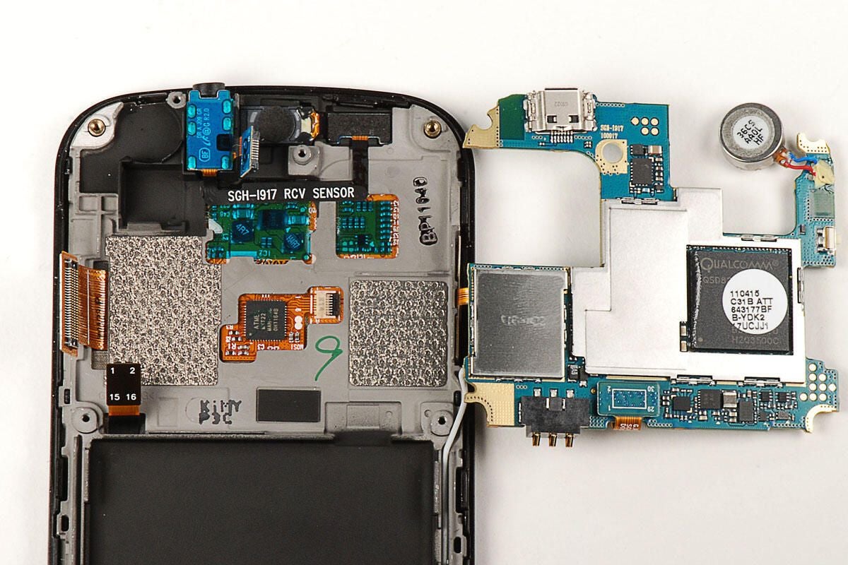
Photo by: Bill Detwiler / TechRepublic
Caption by: Bill Detwiler
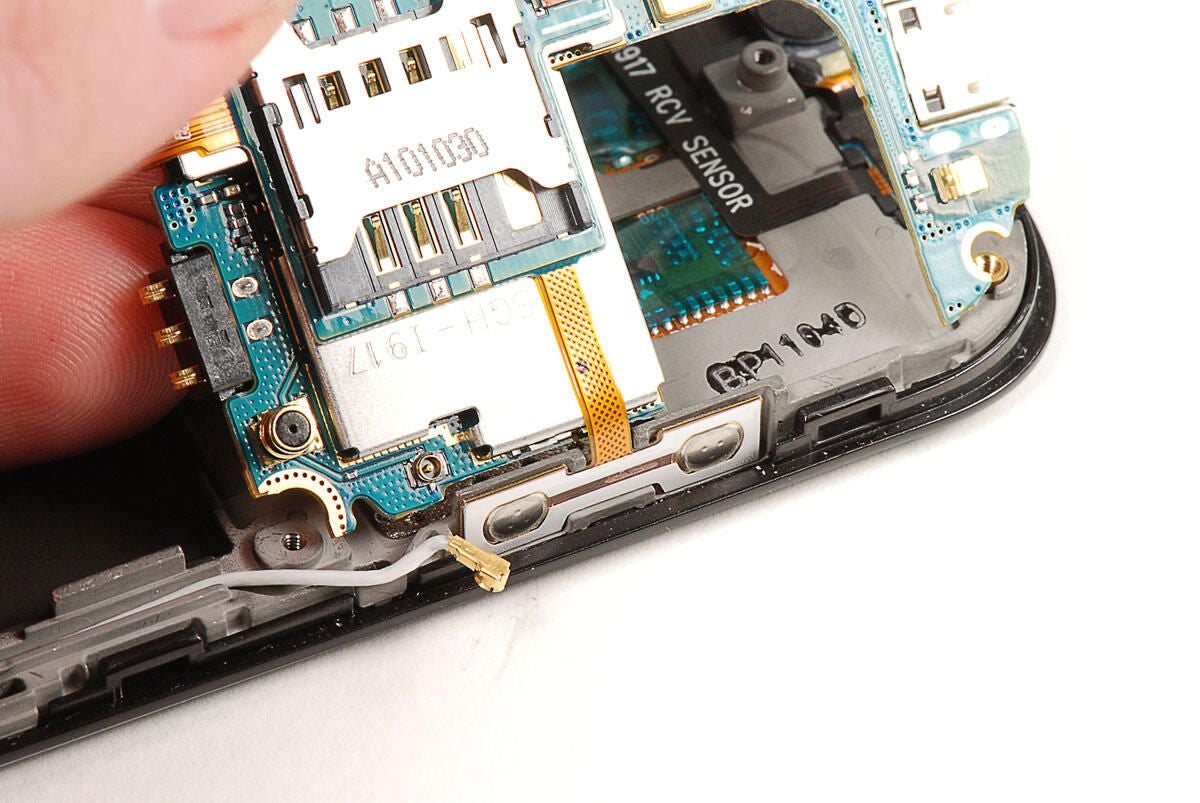
The volume up/down button contacts are attached to the display assembly with adhesive. We’ll need to pry them loose to further dissect the PCBs.
Photo by: Bill Detwiler / TechRepublic
Caption by: Bill Detwiler
Using a thin metal blade, I was able to very gently pry the volume up/down button contacts away from the display assembly.
Photo by: Bill Detwiler / TechRepublic
Caption by: Bill Detwiler
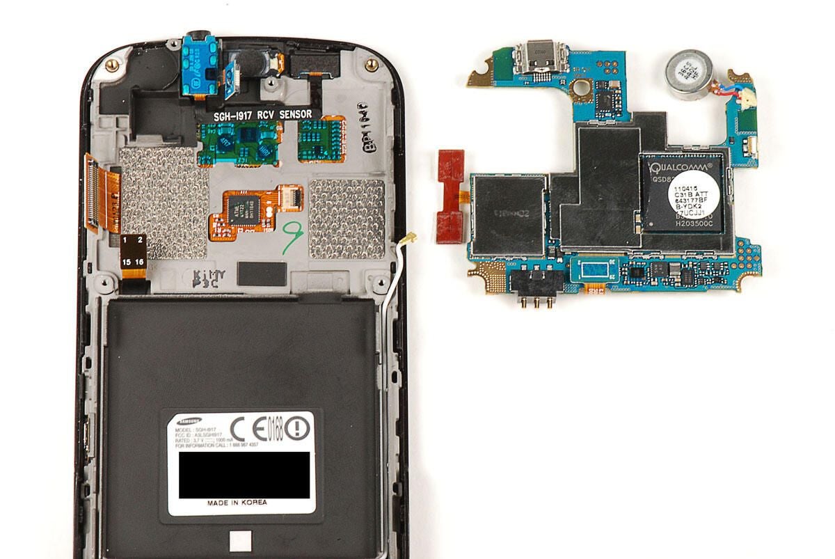
Photo by: Bill Detwiler / TechRepublic
Caption by: Bill Detwiler
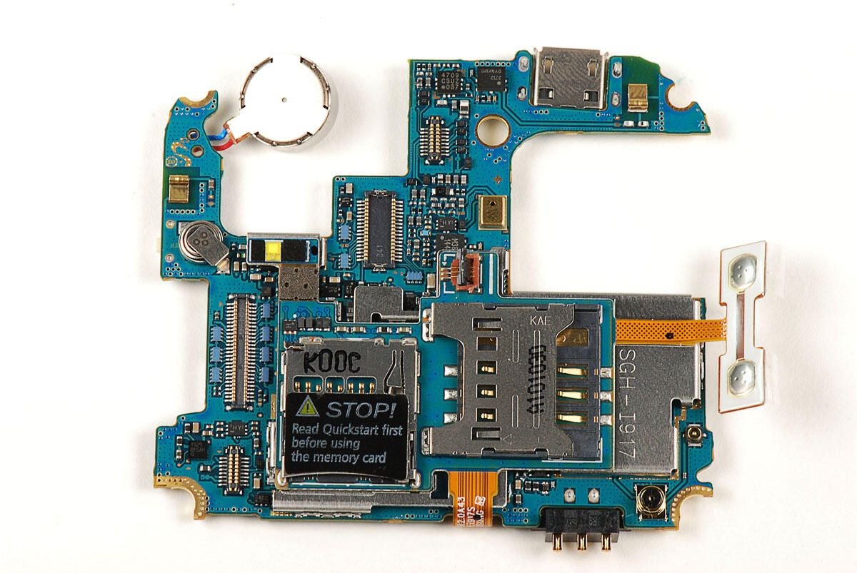
Photo by: Bill Detwiler / TechRepublic
Caption by: Bill Detwiler
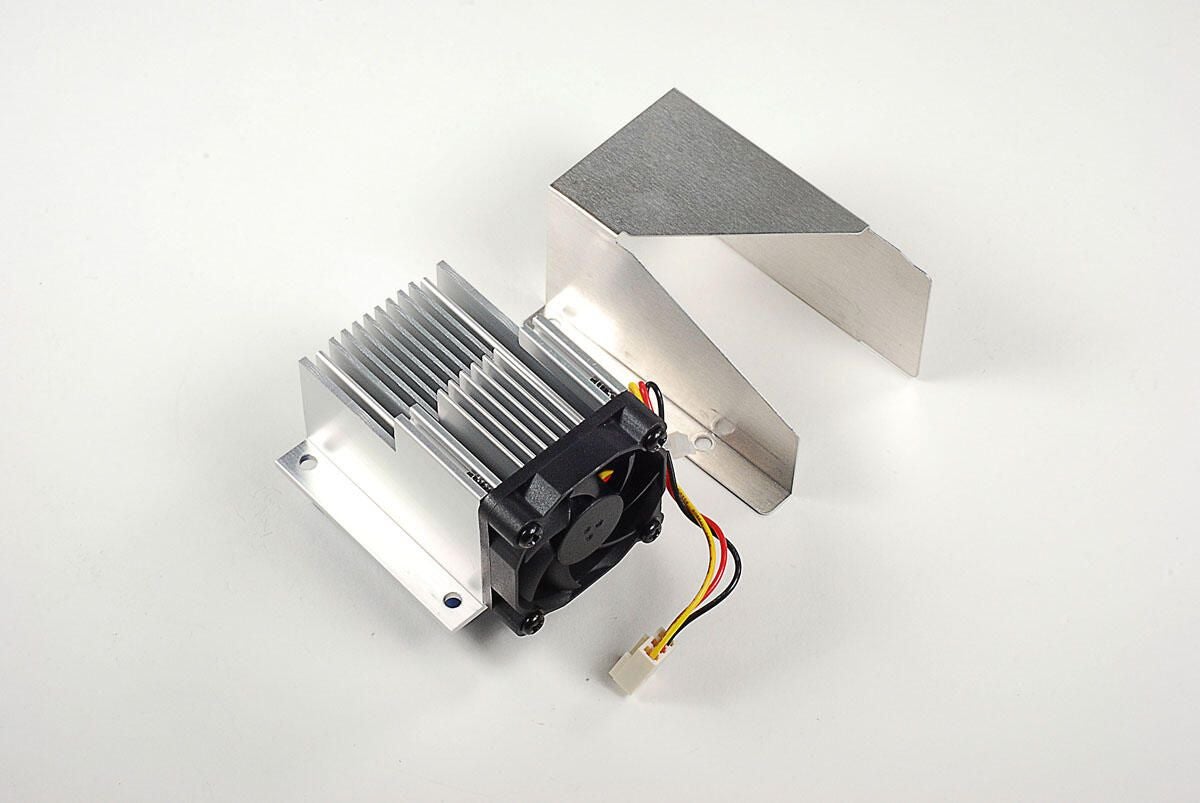
We’ll need to remove the metal EMI shields to see the chips underneath.
Photo by: Bill Detwiler / TechRepublic
Caption by: Bill Detwiler
You’ll need to pop loose this connector before separating the small PCB from the main PCB.
Photo by: Bill Detwiler / TechRepublic
Caption by: Bill Detwiler
The small, upper PCB is glued to the top of a metal EMI shield. Using a thin metal blade, you can pop the EMI shield (and small PCB) away from the main PCB.
With the small PCB and shield removed, we get our first glimpse of the chips on the main PCB.
Photo by: Bill Detwiler / TechRepublic
Caption by: Bill Detwiler
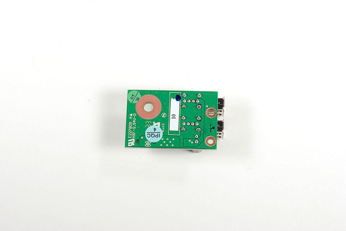
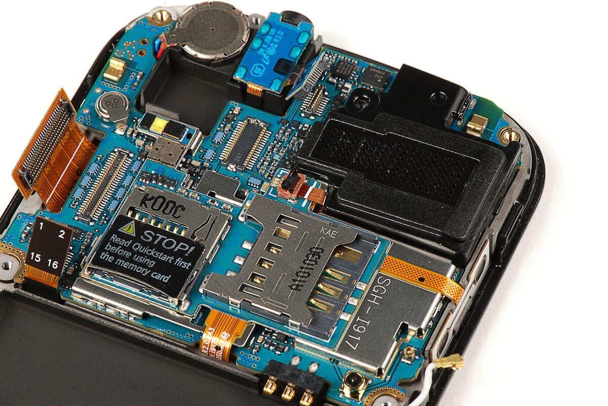
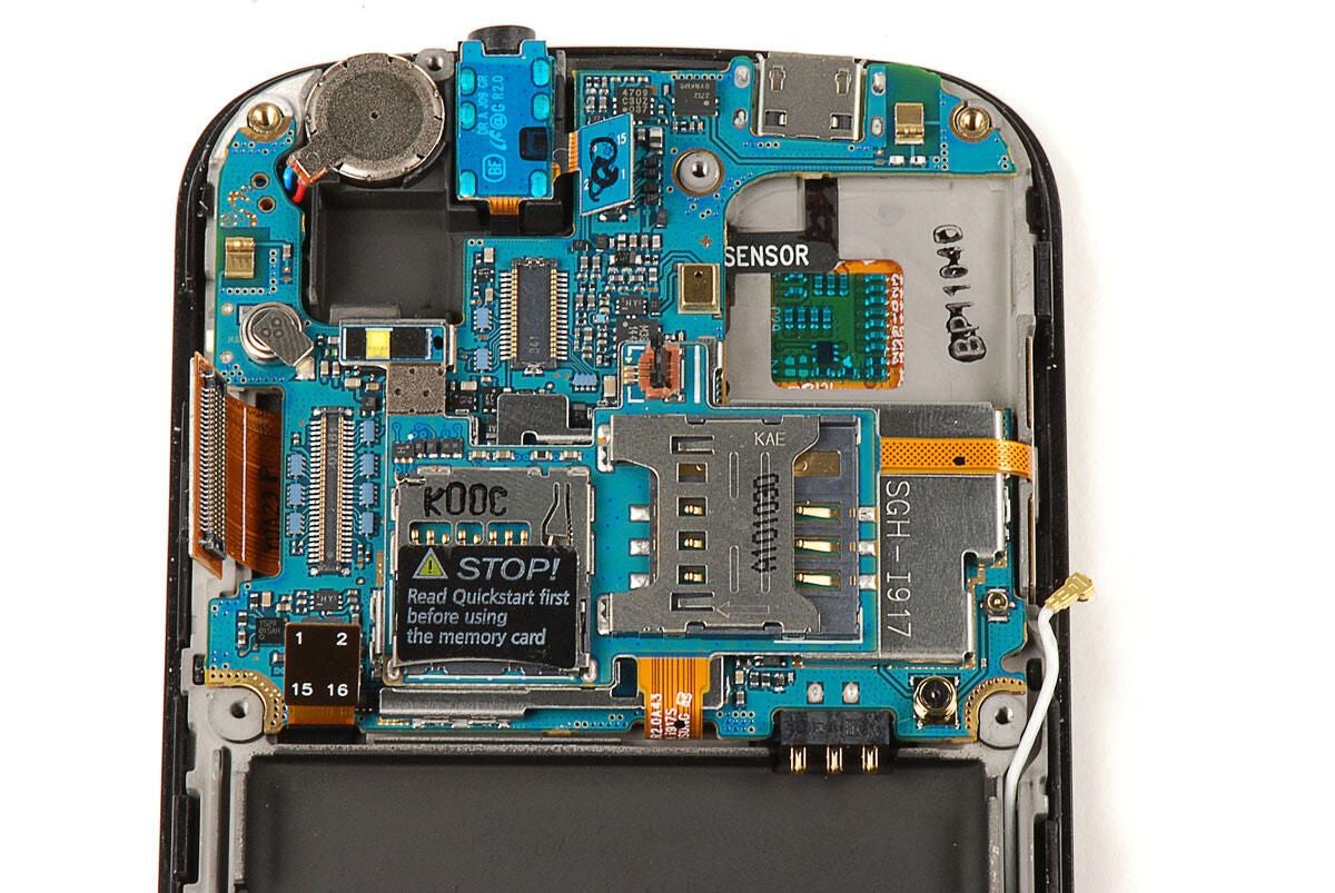
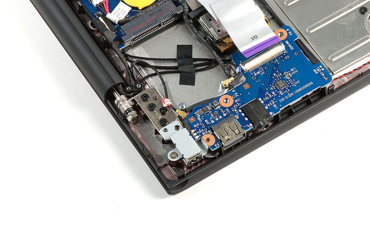
The small PCB contains the Samsung Focus’ SIM slot, microSD card slot, and the contacts for the volume up/down button.
Photo by: Bill Detwiler / TechRepublic
Caption by: Bill Detwiler
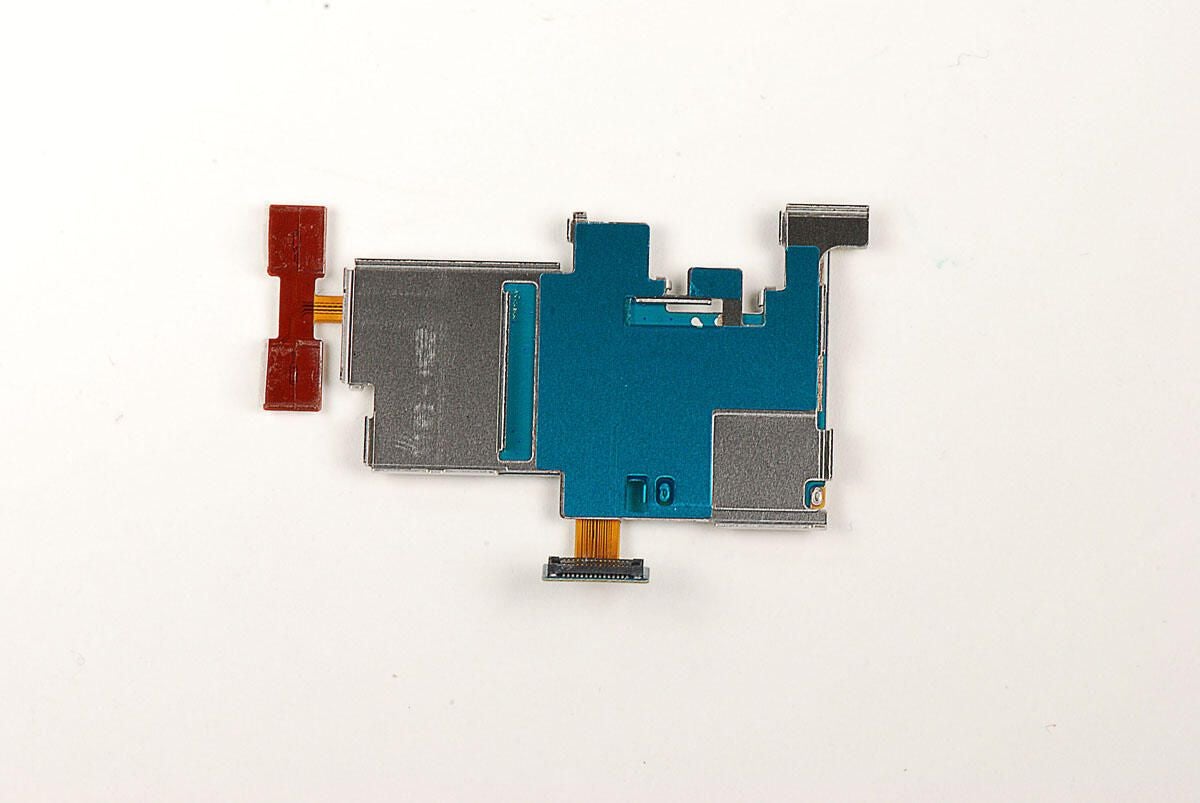
As I previously noted, the small, upper PCB is attached to a metal EMI shield.
Photo by: Bill Detwiler / TechRepublic
Caption by: Bill Detwiler
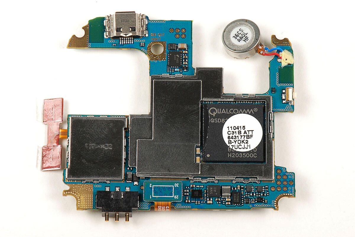
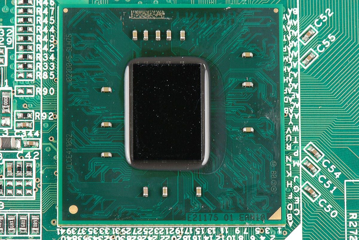
The Samsung Focus has a 1.0GHz Qualcomm QSD8250 Snapdragon processor.
Photo by: Bill Detwiler / TechRepublic
Caption by: Bill Detwiler
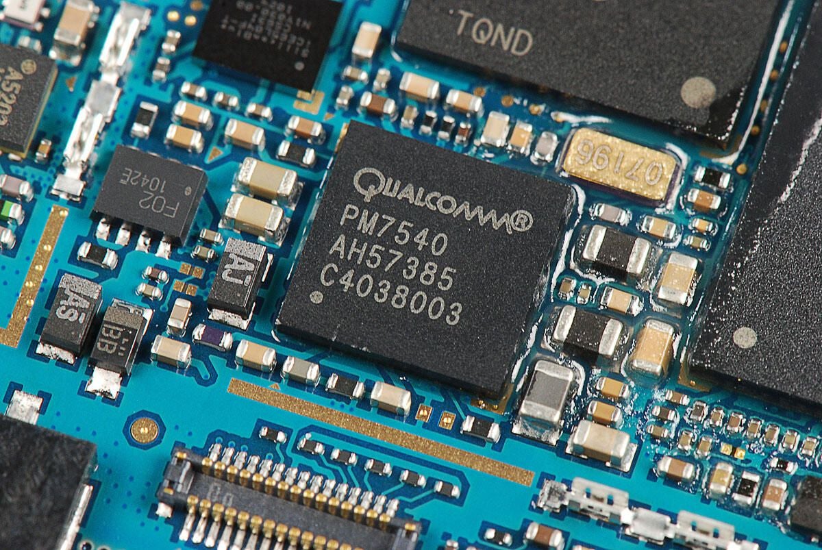
Qualcomm PM7540 power management IC
Photo by: Bill Detwiler / TechRepublic
Caption by: Bill Detwiler
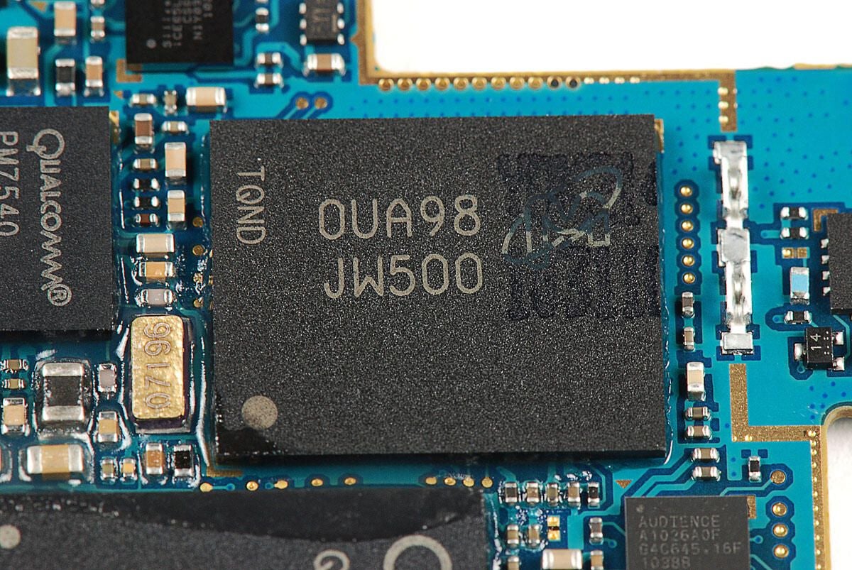
Micron Technology chip with markings:
OUA98 JW500 TQND
Photo by: Bill Detwiler / TechRepublic
Caption by: Bill Detwiler
SiliconBlue Technologies iCE65L04 Ultra Low-Power FPGA
Photo by: Bill Detwiler / TechRepublic
Caption by: Bill Detwiler
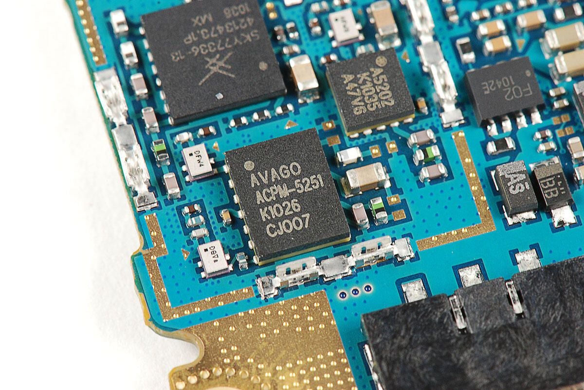
Photo by: Bill Detwiler / TechRepublic
Caption by: Bill Detwiler
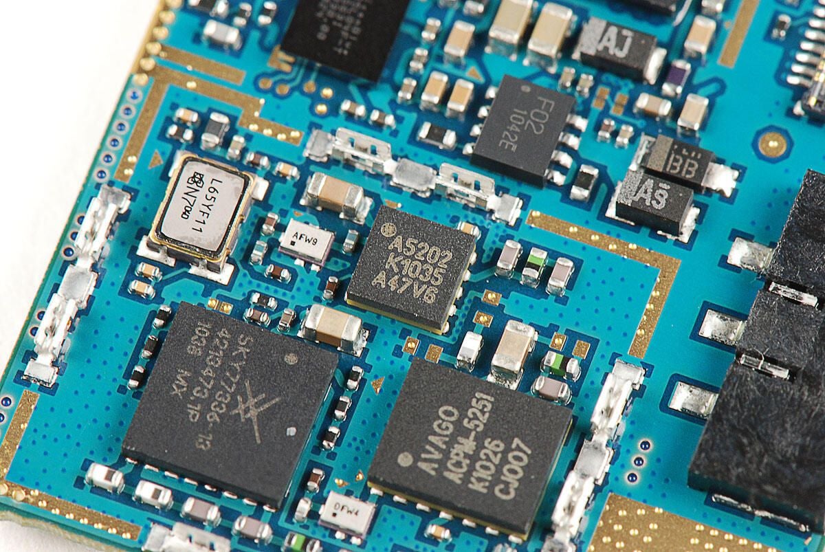
Chip with markings:
A5202 K1035 A47V6
Photo by: Bill Detwiler / TechRepublic
Caption by: Bill Detwiler
Skyworks SKY77336 Power Amplifier Module
Photo by: Bill Detwiler / TechRepublic
Caption by: Bill Detwiler
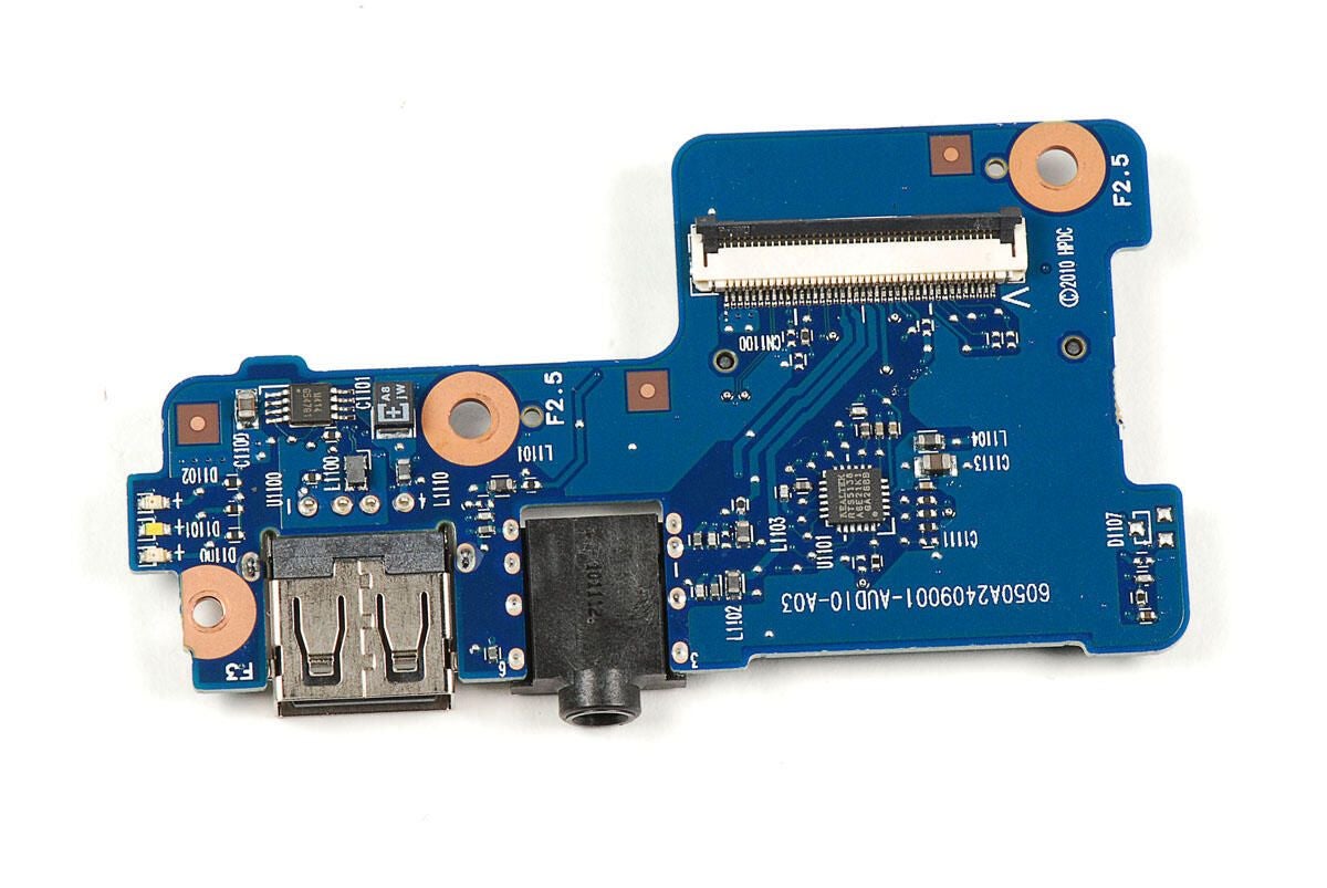
Fairchild Semiconductor FSA9280A USB 2.0 Accessory Detection Switch w/ 28V FET
According to the company’s website:
“These switches allow the sharing of a common USB port to pass audio, USB data / charging, as well as factory programmability. In addition, the FSA9280A / FSA9288A integrate detection of accessories, such as headphones, headsets (MIC / button), car chargers, USB chargers, and UART data cables with the ability to use a common USB connector.”
Photo by: Bill Detwiler / TechRepublic
Caption by: Bill Detwiler
More Miscellaneous chips located below the processor.
Photo by: Bill Detwiler / TechRepublic
Caption by: Bill Detwiler
After working our way through the chips on the top of the main PCB, let’s turn our attention to the chips on the bottom.
Photo by: Bill Detwiler / TechRepublic
Caption by: Bill Detwiler
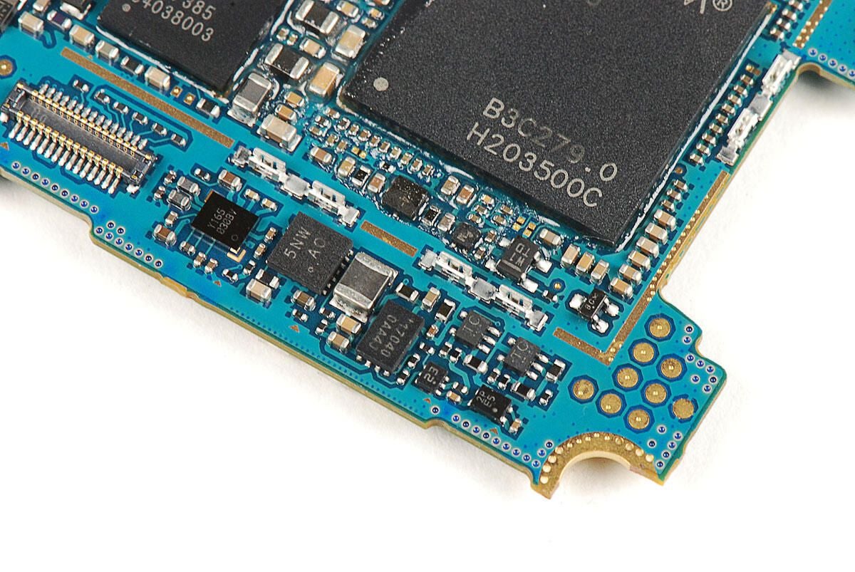
SanDisk SDIN4C2-8G 8GB NAND flash RAM
Photo by: Bill Detwiler / TechRepublic
Caption by: Bill Detwiler
Qualcomm RTR6285 UMTS/GSM/EDGE cellular transceiver
Photo by: Bill Detwiler / TechRepublic
Caption by: Bill Detwiler
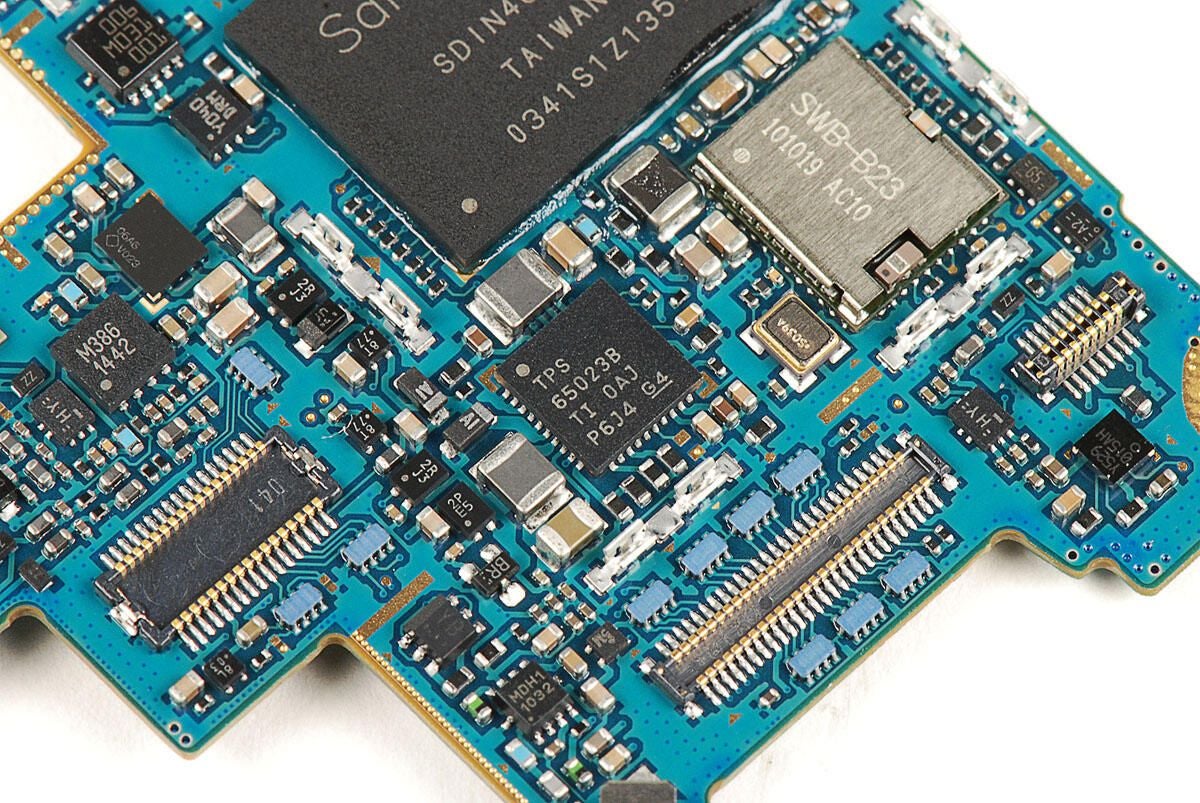
Texas Instruments TPS65023B 6-channel Power Management IC
Photo by: Bill Detwiler / TechRepublic
Caption by: Bill Detwiler
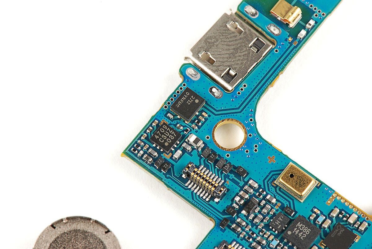
Photo by: Bill Detwiler / TechRepublic
Caption by: Bill Detwiler
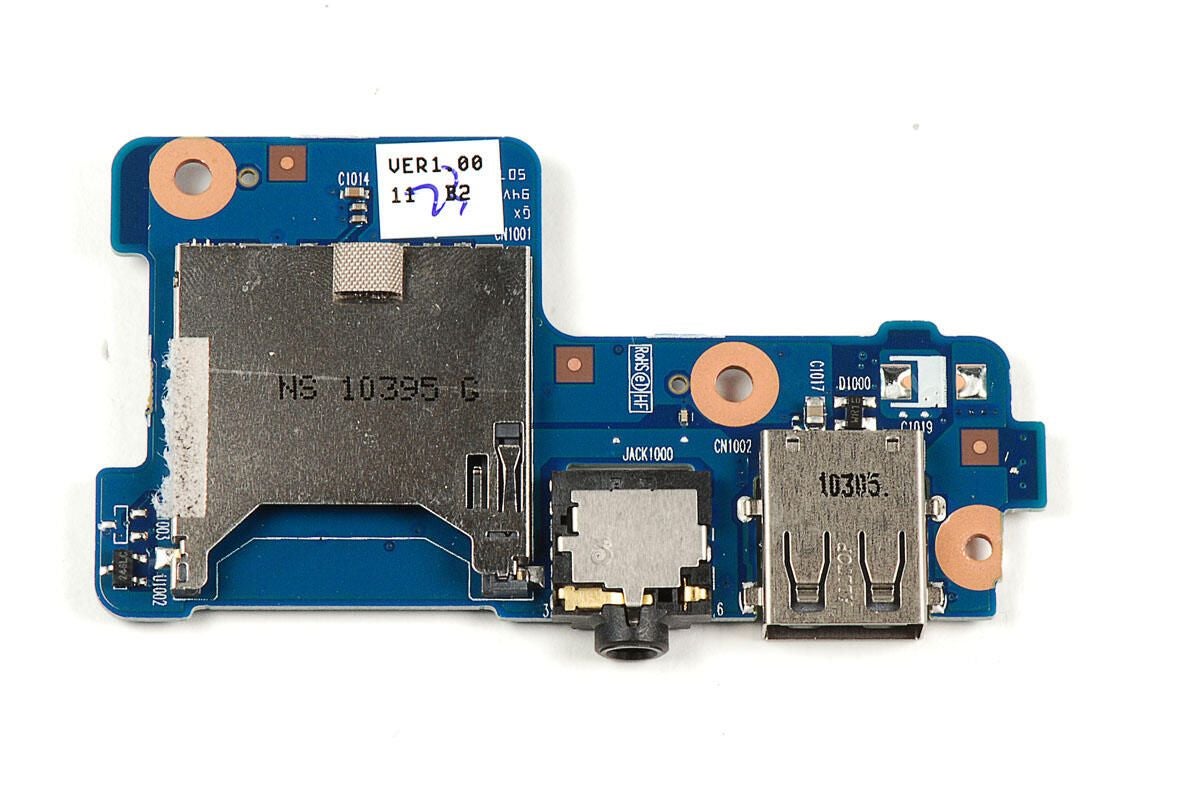
Photo by: Bill Detwiler / TechRepublic
Caption by: Bill Detwiler
Avago AFI037 1512BB
Photo by: Bill Detwiler / TechRepublic
Caption by: Bill Detwiler
The screen and display assembly are attached to the front panel with strong adhesive. As I want to reassemble this Samsung Focus in working order, I’m going to leave these components connected.
Photo by: Bill Detwiler / TechRepublic
Caption by: Bill Detwiler
Atmel mXT224 224-node touchscreen microcontroller
Photo by: Bill Detwiler / TechRepublic
Caption by: Bill Detwiler
The Samsung Focus was surprisingly easy to disassemble. It has standard Phillips screws and several easily-removable internal components. Unfortunately, the display assembly is held in place with strong adhesive. A heat gun or hair dryer could be used to loosen the glue during repair, but it should be a last resort.
Photo by: Bill Detwiler / TechRepublic
Caption by: Bill Detwiler
Bill Detwiler is the Editor for Technical Content and Ecosystem at Celonis. He is the former Editor in Chief of TechRepublic and previous host of TechRepublic's Dynamic Developer podcast and Cracking Open, CNET and TechRepublic's popular online show. Previously, Bill was an IT manager in the social research and energy industries. He has bachelor's and master's degrees from the University of Louisville, where he has also lectured on computer crime and crime prevention.
