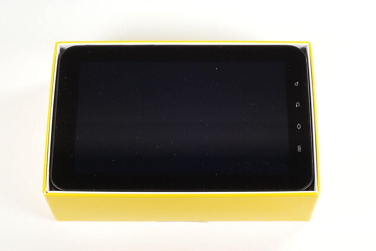
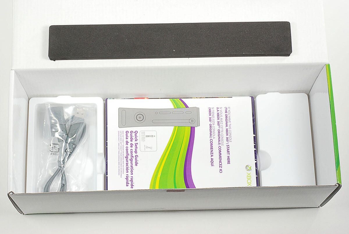
In the box are the PSP Go unit, the AC power adapter and cord, Media Go CD-ROM, and product documentation.
Photo by: Bill Detwiler / TechRepublic
Caption by: Bill Detwiler
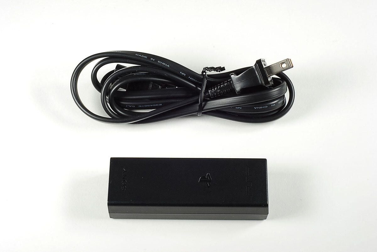
Photo by: Bill Detwiler / TechRepublic
Caption by: Bill Detwiler
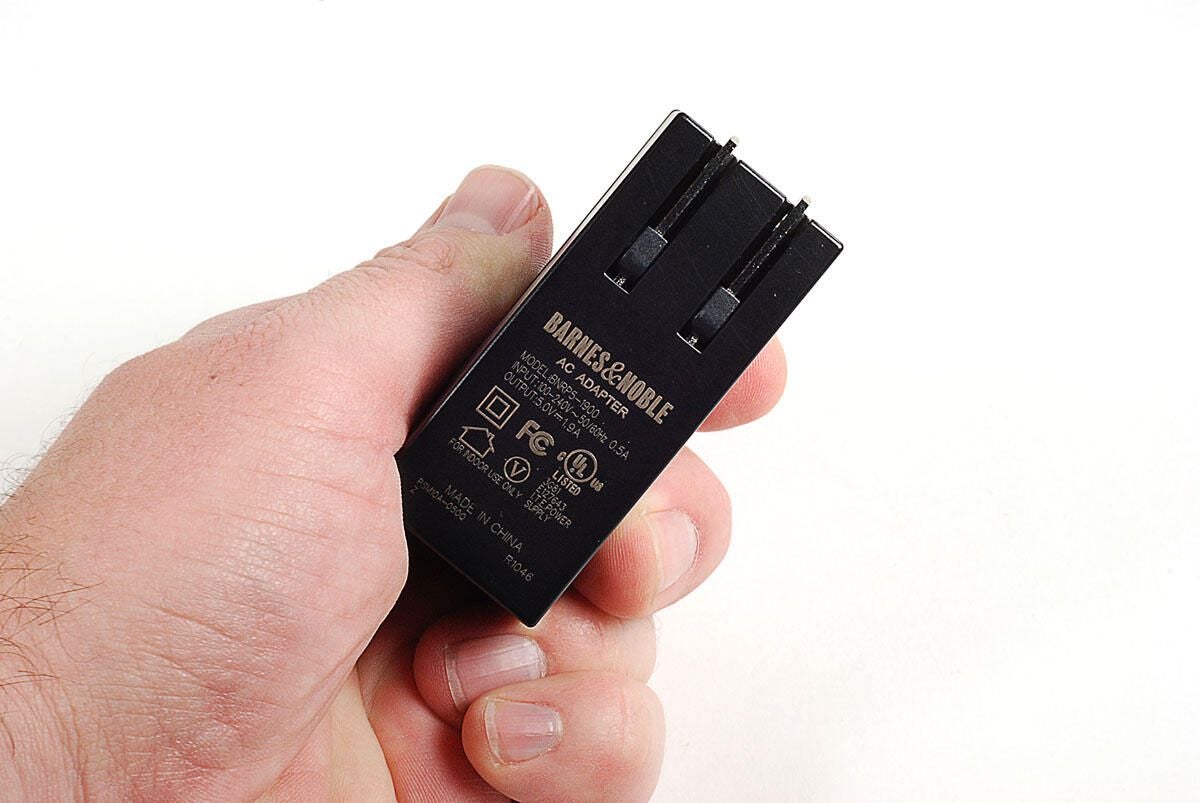
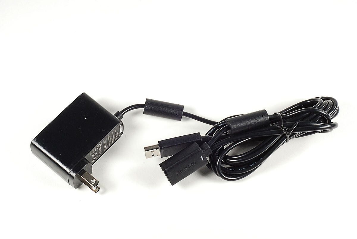
The PSP Go has a 5V AC adapter.
Photo by: Bill Detwiler / TechRepublic
Caption by: Bill Detwiler
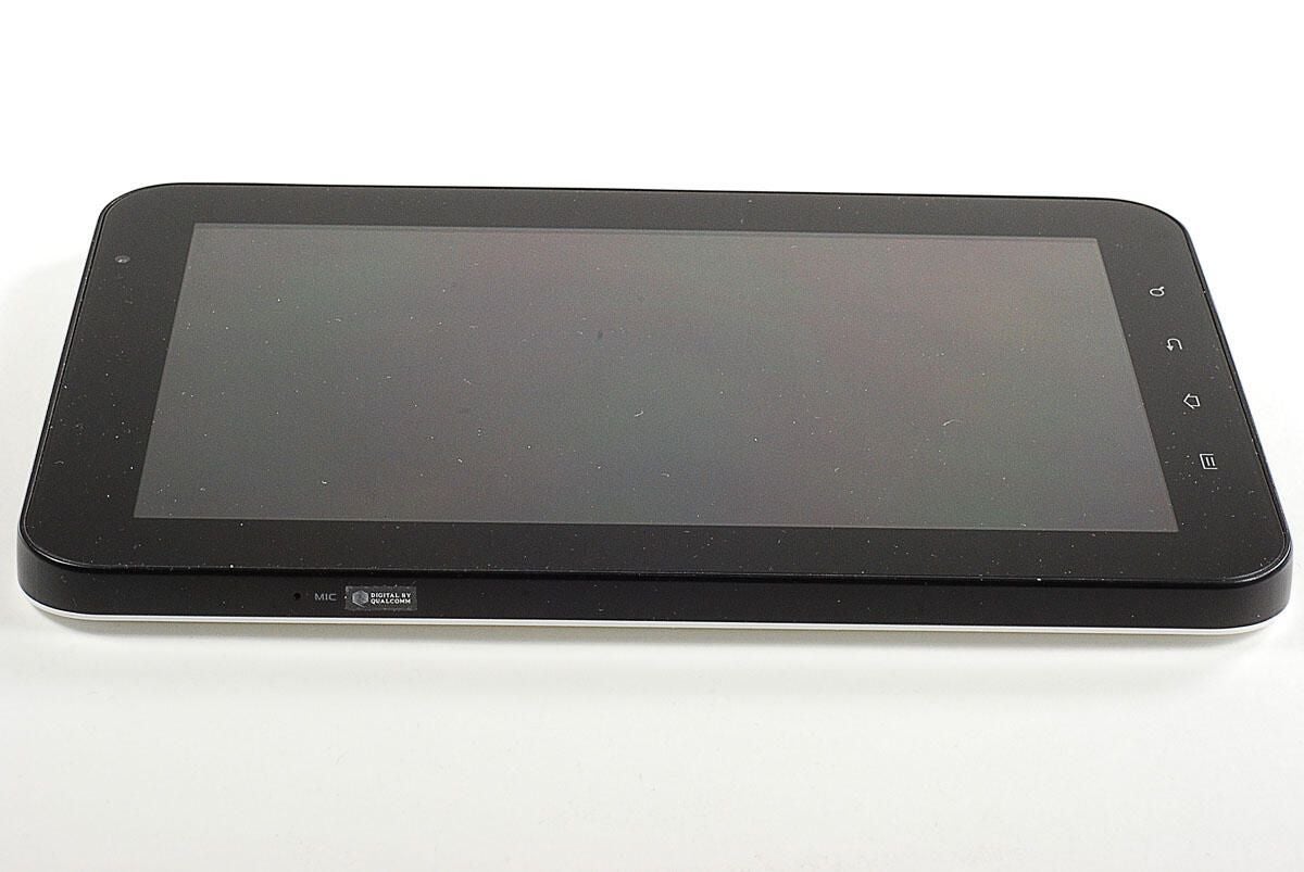
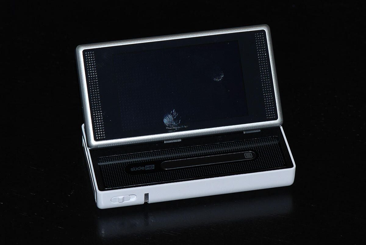
With the display panel closed, we can see the speakers, WLAN indicator, Bluetooth indicator, and PS button on the front of the PSP Go.
Photo by: Bill Detwiler / TechRepublic
Caption by: Bill Detwiler
With the display panel open, we can see the directional buttons, analog joystick, microphone, Start button, Select button, and control buttons.
Photo by: Bill Detwiler / TechRepublic
Caption by: Bill Detwiler
Photo by: Bill Detwiler / TechRepublic
Caption by: Bill Detwiler
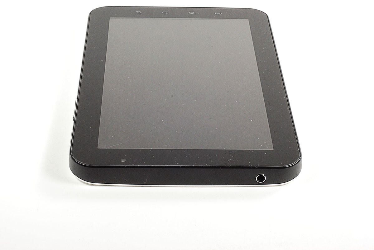
On the bottom of the PSP Go are the multi-use connector and headset connector.
Photo by: Bill Detwiler / TechRepublic
Caption by: Bill Detwiler
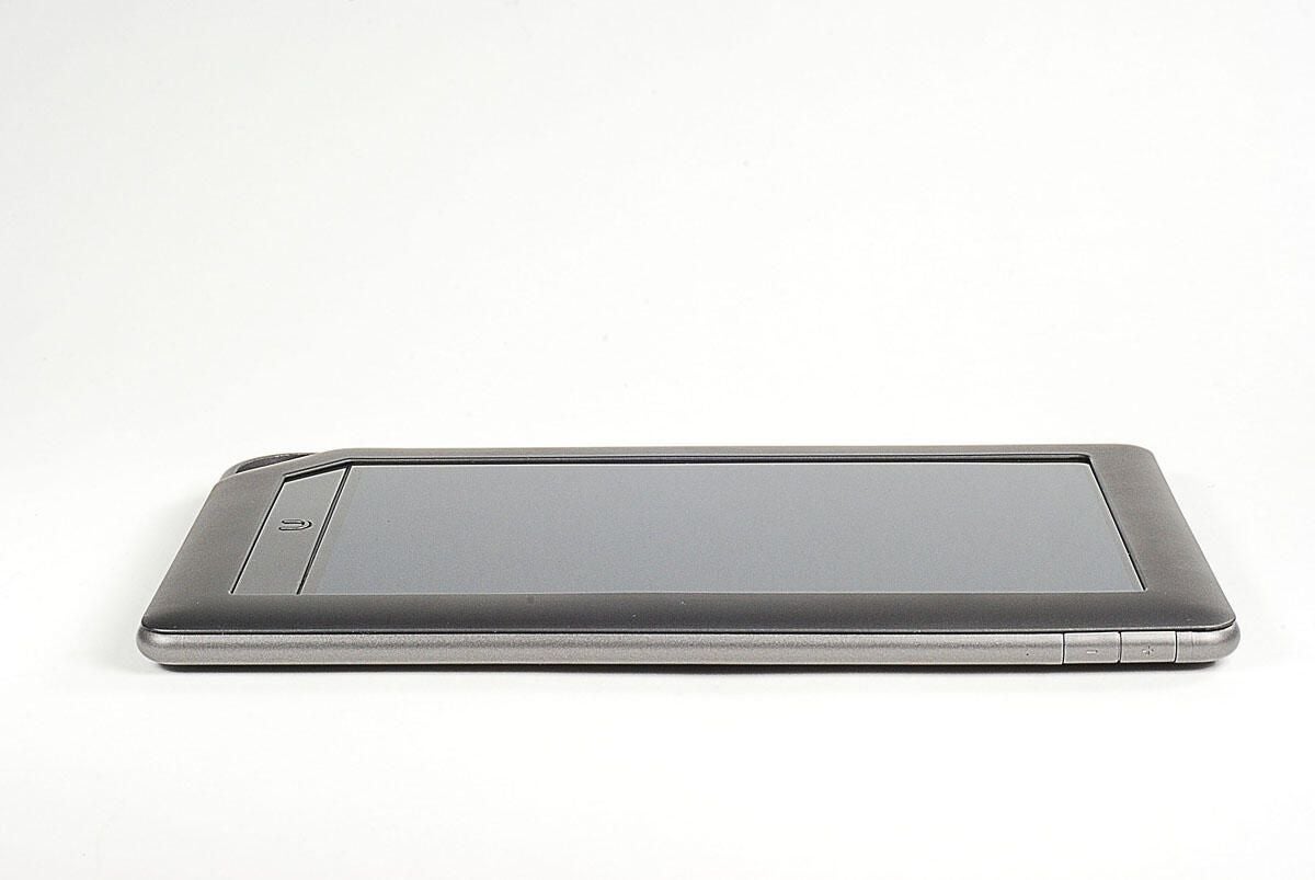
On the top of the PSP Go are the L button (left trigger), display button, volume up/down button, sound button, and R button (right trigger).
Photo by: Bill Detwiler / TechRepublic
Caption by: Bill Detwiler
Along the left side of the PSP Go are the Memory Stick Micro slot, Memory Stick Micro indicator, wireless switch, and strap holder.
Photo by: Bill Detwiler / TechRepublic
Caption by: Bill Detwiler
Along the right side of the PSP Go are the power indicator and the power/hold button.
Photo by: Bill Detwiler / TechRepublic
Caption by: Bill Detwiler
The first step in disassembling the PSP Go is to remove the four Phillips #00 screws on the back panel.
Photo by: Bill Detwiler / TechRepublic
Caption by: Bill Detwiler
Two more Phillips #00 screws are located along the PSP Go’s top edge. You’ll also need to remove these.
Photo by: Bill Detwiler / TechRepublic
Caption by: Bill Detwiler
With all six external screws removed, you can lift the back panel away from the case.
Photo by: Bill Detwiler / TechRepublic
Caption by: Bill Detwiler
Photo by: Bill Detwiler / TechRepublic
Caption by: Bill Detwiler
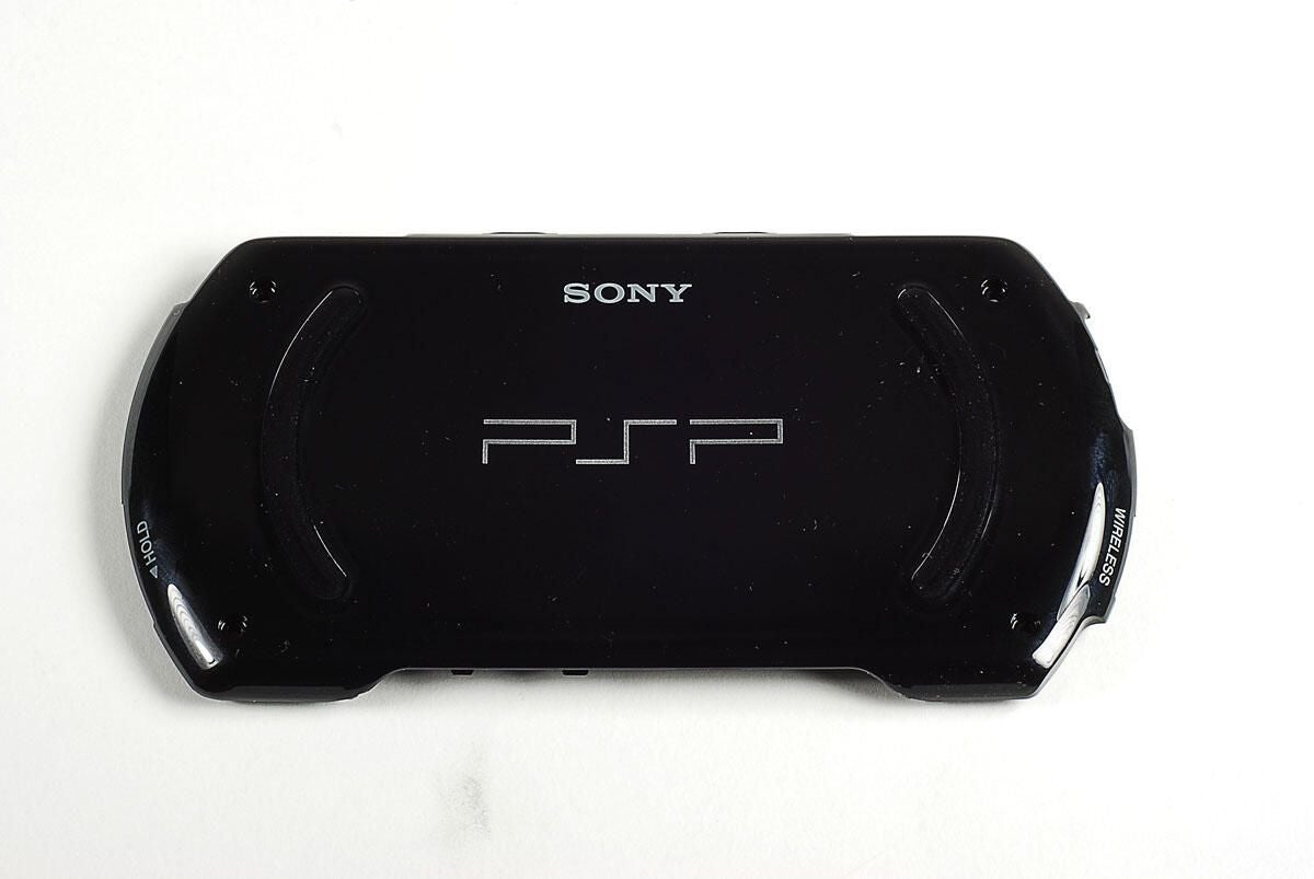
Photo by: Bill Detwiler / TechRepublic
Caption by: Bill Detwiler
With the back panel removed, we get our first look inside the PSP Go. Unfortunately, this is about as far as you can go without voiding your warranty.
Photo by: Bill Detwiler / TechRepublic
Caption by: Bill Detwiler
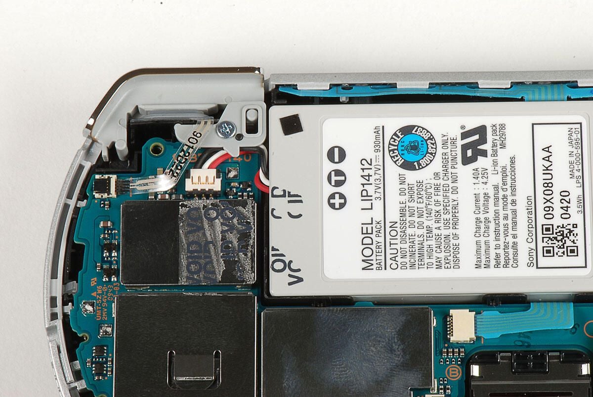
With the warranty sticker removed, we can see the battyer connector.
Photo by: Bill Detwiler / TechRepublic
Caption by: Bill Detwiler
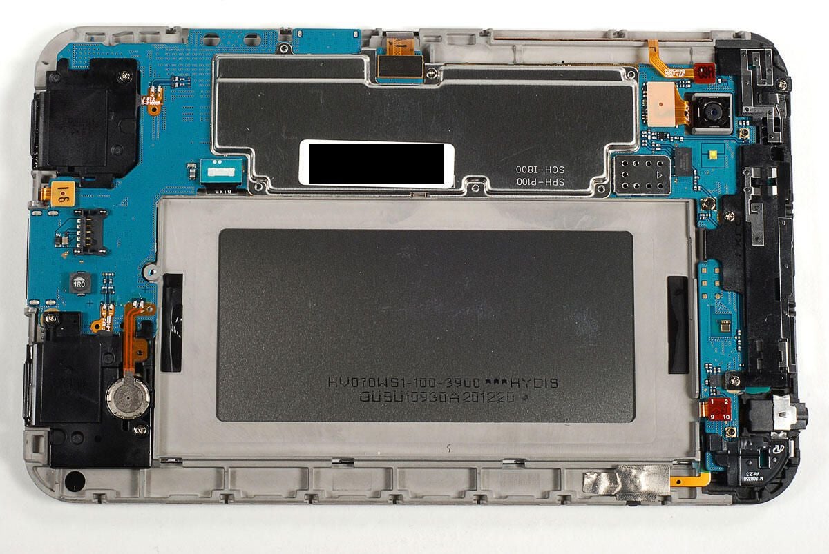
Photo by: Bill Detwiler / TechRepublic
Caption by: Bill Detwiler
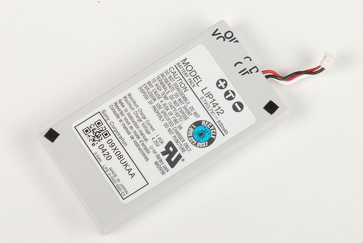
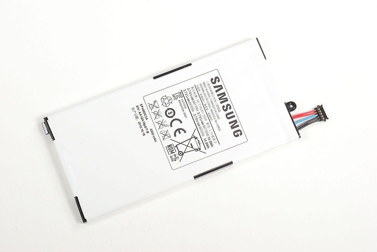
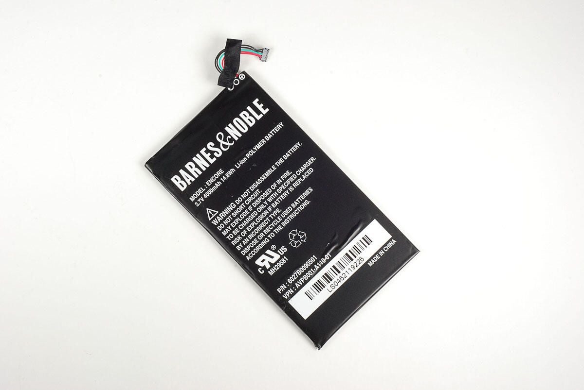
The PSP Go has a 3.7V Li-ion battery.
Photo by: Bill Detwiler / TechRepublic
Caption by: Bill Detwiler
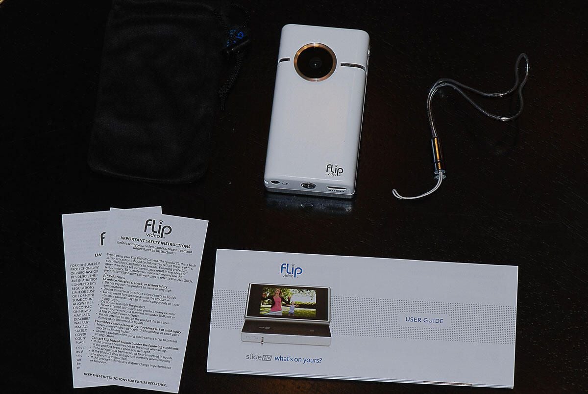
Photo by: Bill Detwiler / TechRepublic
Caption by: Bill Detwiler
With the battery and back panel removed, the thin plastic cover the run along the top of the PSP Go should pop off.
Photo by: Bill Detwiler / TechRepublic
Caption by: Bill Detwiler
Before removing the logic board, we’ll need to remove the two trigger buttons. A single Phillips screw holds each in place.
Photo by: Bill Detwiler / TechRepublic
Caption by: Bill Detwiler
Before removing the triggers, you’ll also have to disconnect their ribbon cables.
Photo by: Bill Detwiler / TechRepublic
Caption by: Bill Detwiler
Photo by: Bill Detwiler / TechRepublic
Caption by: Bill Detwiler
Two screws hold the plastic cover that runs along the PSP Go’s bottom edge in place. You’ll need to remove both screws before removing the cover.
Photo by: Bill Detwiler / TechRepublic
Caption by: Bill Detwiler
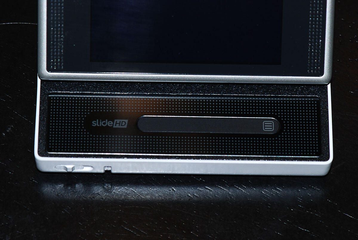
Photo by: Bill Detwiler / TechRepublic
Caption by: Bill Detwiler
A single screw and thin ribbon cable hold the PSP Go’s headphone jack in place.
Photo by: Bill Detwiler / TechRepublic
Caption by: Bill Detwiler
Photo by: Bill Detwiler / TechRepublic
Caption by: Bill Detwiler
To the left of the headphone jack is the screw for the analog joystick.
Photo by: Bill Detwiler / TechRepublic
Caption by: Bill Detwiler
With the screw removed, you can disconnect the analog joystick’s ribbon cable and separate it from the logic board.
Photo by: Bill Detwiler / TechRepublic
Caption by: Bill Detwiler
Photo by: Bill Detwiler / TechRepublic
Caption by: Bill Detwiler
A single screw remains in the logic board.
Photo by: Bill Detwiler / TechRepublic
Caption by: Bill Detwiler
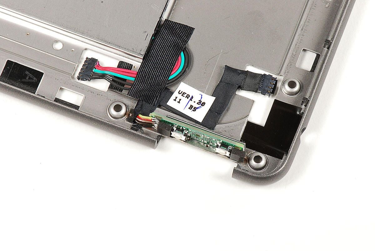
With all the screws removed, you’ll also need to disconnect several ribbon cables from the logic board.
Photo by: Bill Detwiler / TechRepublic
Caption by: Bill Detwiler
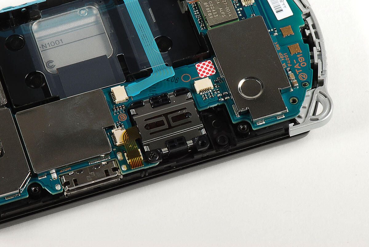
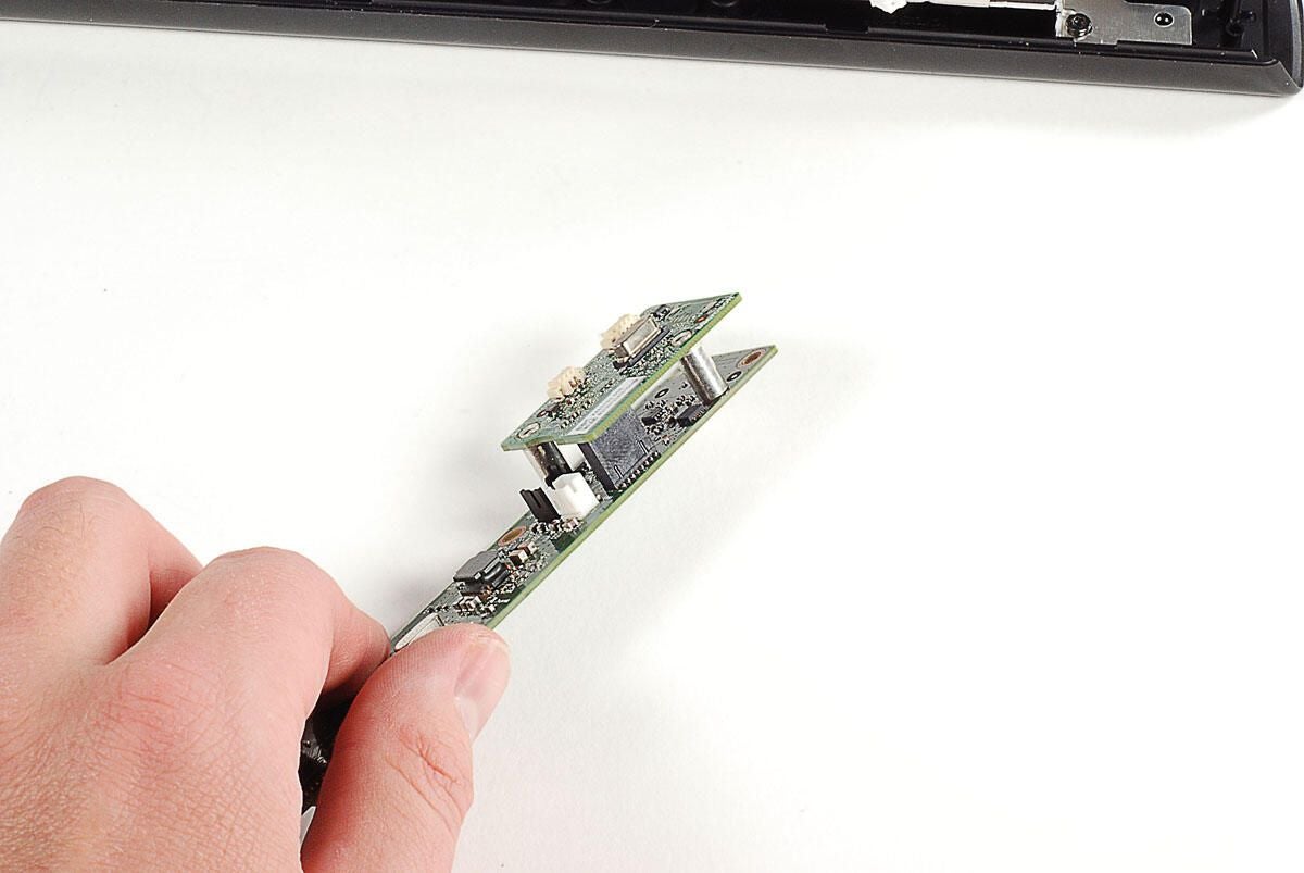
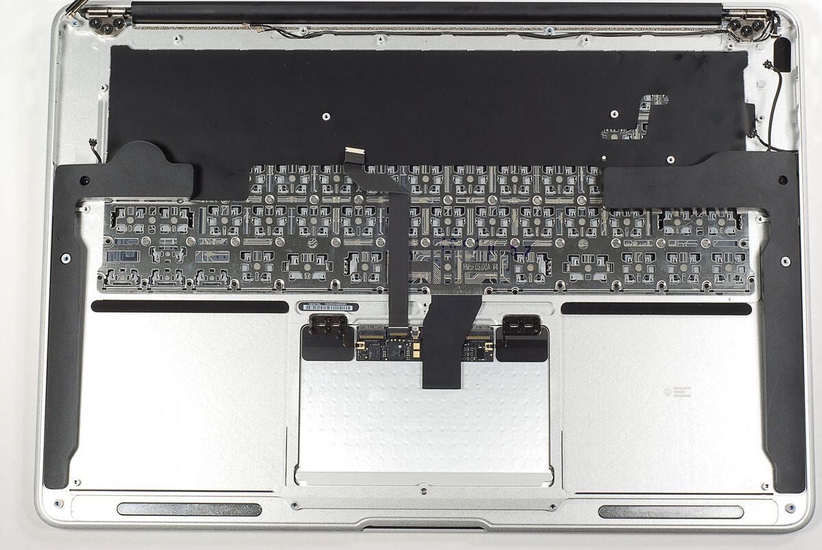
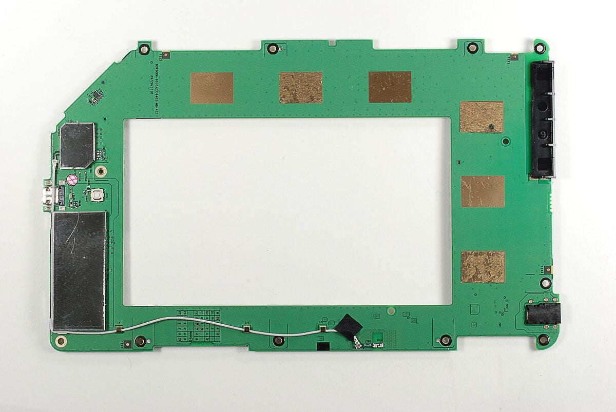
With all the screws removed and the ribbon cables disconnected, you can lift the logic board from the case.
Photo by: Bill Detwiler / TechRepublic
Caption by: Bill Detwiler
We’ll turn our attention back to the logic board in a bit. But now, let’s concentrate on the case and the components that remain inside.
Photo by: Bill Detwiler / TechRepublic
Caption by: Bill Detwiler
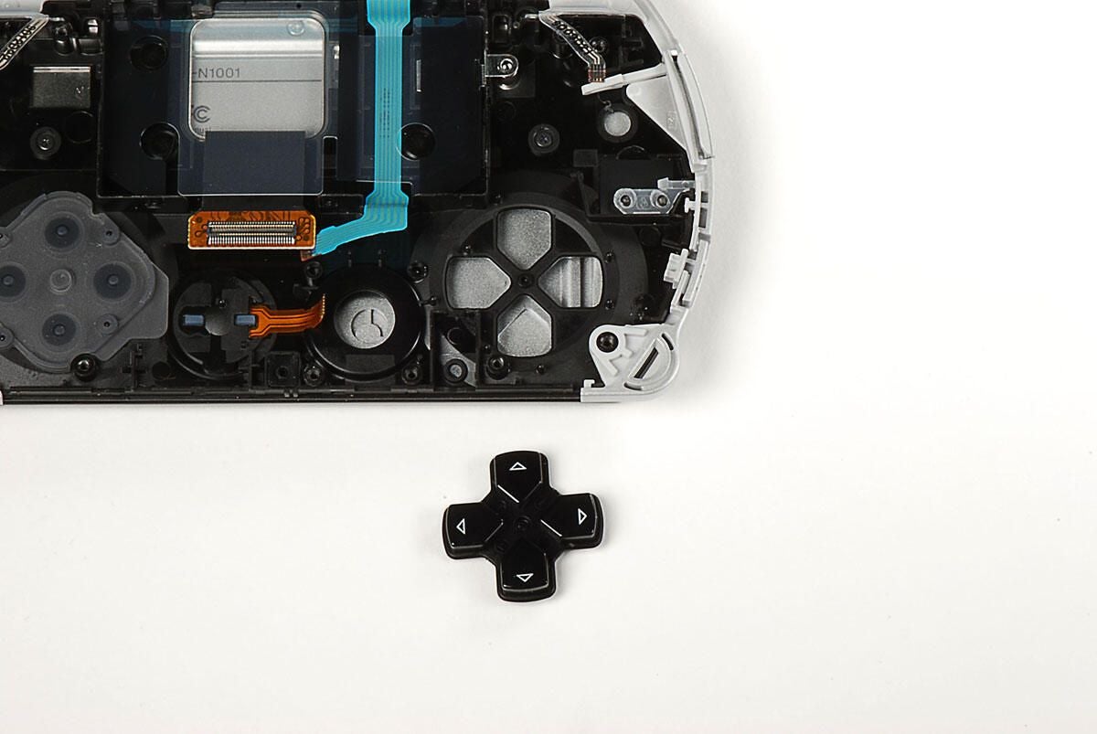
The direction buttons are part of a single cross-shaped button. It should just fall from the case.
Photo by: Bill Detwiler / TechRepublic
Caption by: Bill Detwiler
Four small, black screws remain in the case. These screws hold the sliding display assembly to the black plastic case. You’ll need to remove all four screws.
Photo by: Bill Detwiler / TechRepublic
Caption by: Bill Detwiler
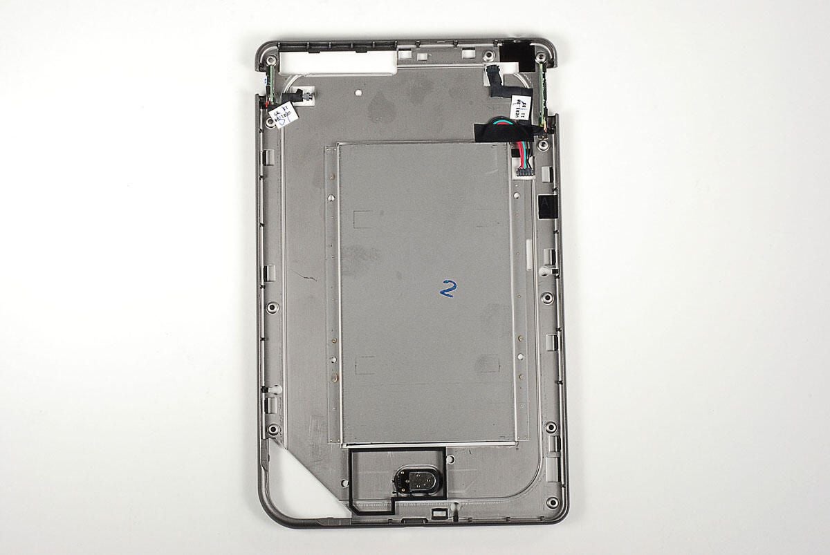
With the display assembly removed, you can more easily see the four screws holes in the black plastic case.
Photo by: Bill Detwiler / TechRepublic
Caption by: Bill Detwiler
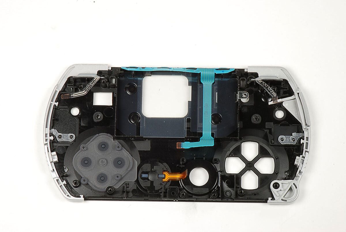
At this point, there’s not much left attached to the PSP Go’s case.
Photo by: Bill Detwiler / TechRepublic
Caption by: Bill Detwiler
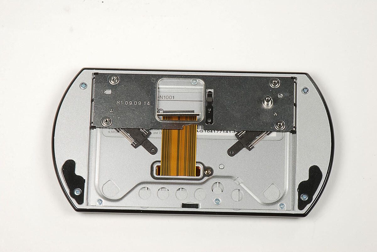
Photo by: Bill Detwiler / TechRepublic
Caption by: Bill Detwiler
The display assembly contains the sliding hinge, a base plate, the display, and the exterior plastic frame. There are a total of 10 screws on the back of the display assembly. Six of the screws hold the hinge to the plastic base plate. You don’t need to remove these.
The four outer screws hold the display’s exterior frame (and thus the display) to the base plate. You’ll need to remove these four screws to remove the display.
Photo by: Bill Detwiler / TechRepublic
Caption by: Bill Detwiler
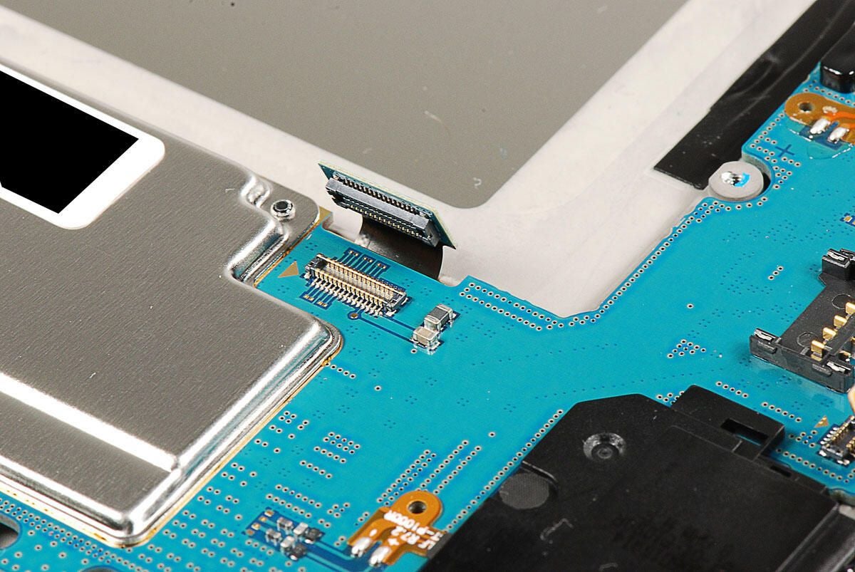
A thin ribbon cable connects the display plate to the display. You’ll need to disconnect this cable before proceeding.
Photo by: Bill Detwiler / TechRepublic
Caption by: Bill Detwiler
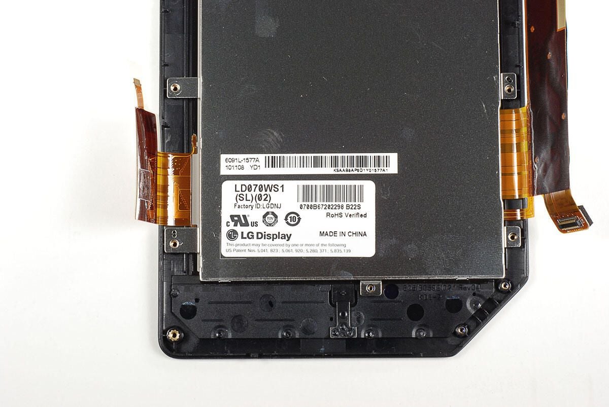
Photo by: Bill Detwiler / TechRepublic
Caption by: Bill Detwiler
Photo by: Bill Detwiler / TechRepublic
Caption by: Bill Detwiler
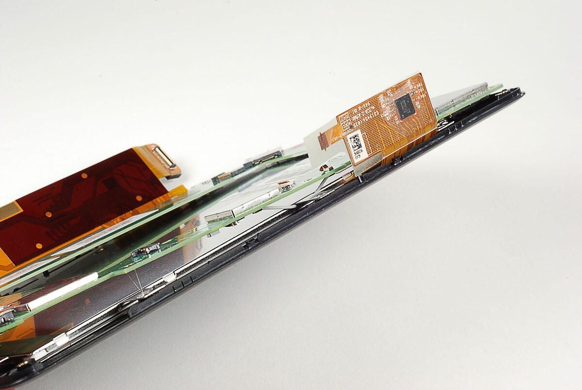
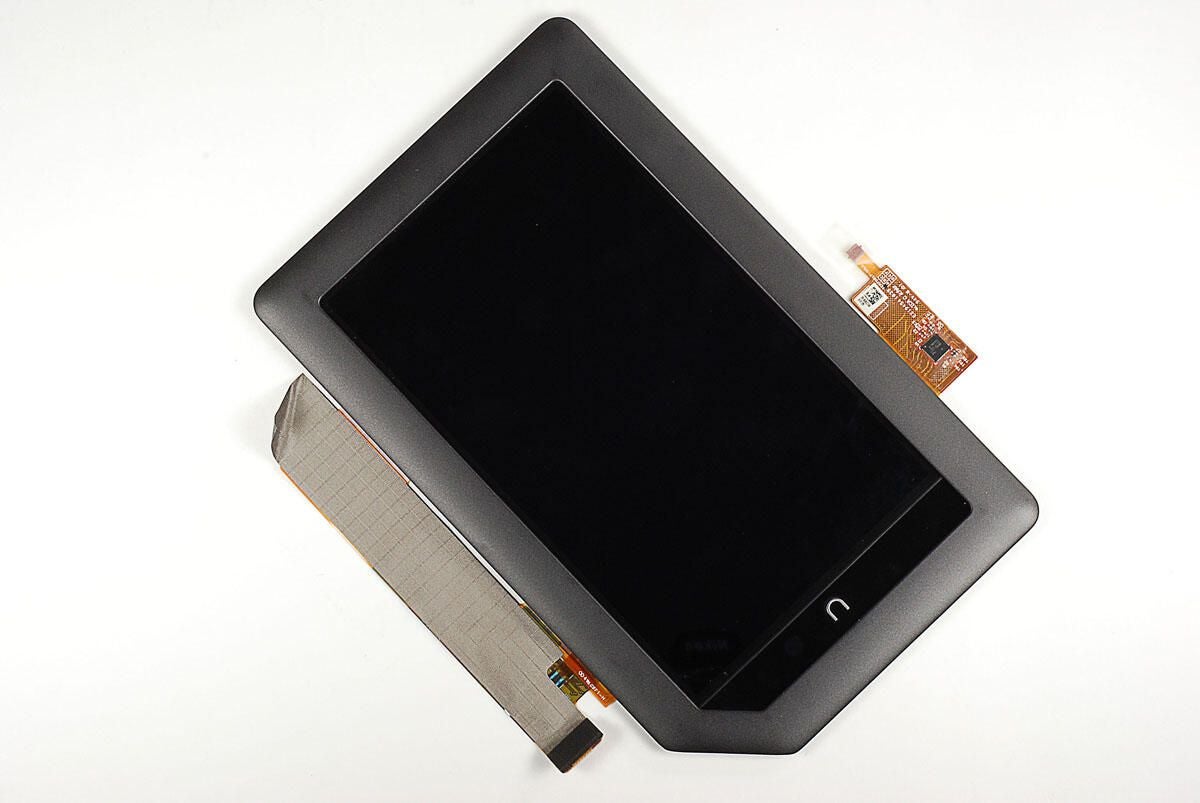
With the base plate removed from the display assembly, you can separate the display screen from the exterior frame. You could use a thin metal blade or a plastic PSP case opening tool. But, I found the my fingernail work just as well and didn’t scratch the frame or display.
Photo by: Bill Detwiler / TechRepublic
Caption by: Bill Detwiler
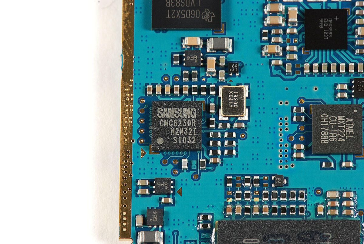
Photo by: Bill Detwiler / TechRepublic
Caption by: Bill Detwiler
The speakers and PS button are still mounted to the display’s frame.
Photo by: Bill Detwiler / TechRepublic
Caption by: Bill Detwiler
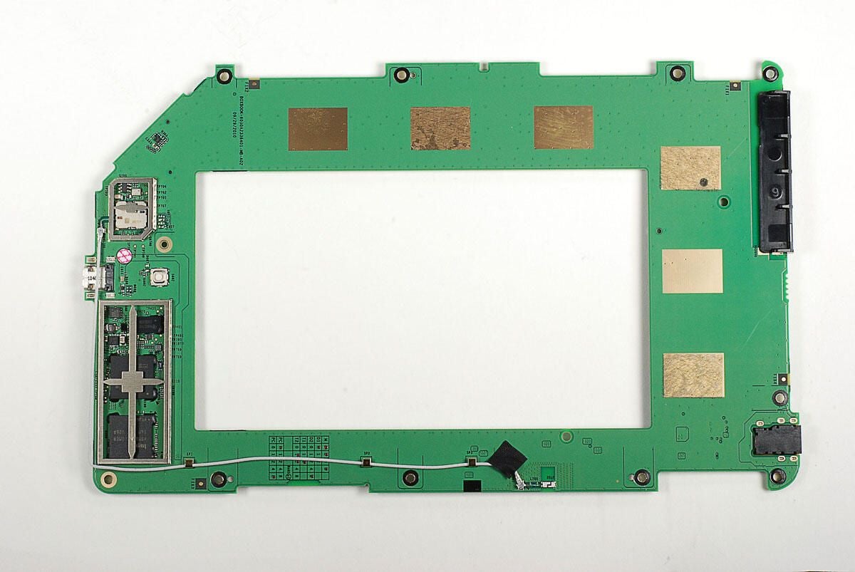
We’ll need to remove the EMI shields before we can see the main chips on the PSP Go’s logic board.
Photo by: Bill Detwiler / TechRepublic
Caption by: Bill Detwiler
Unfortunately, the EMI shield bases have cross beams, which obscure some of the chips. As I want to reassemble this PSP Go in working order, I’m going to leave the beams in place.
Photo by: Bill Detwiler / TechRepublic
Caption by: Bill Detwiler
Sony Computer Entertainment CXD2986A1GG
SL38007C1C0934C9165B
Photo by: Bill Detwiler / TechRepublic
Caption by: Bill Detwiler
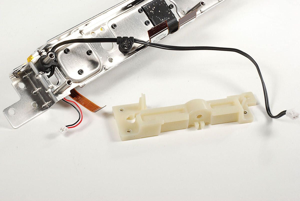
Photo by: Bill Detwiler / TechRepublic
Caption by: Bill Detwiler
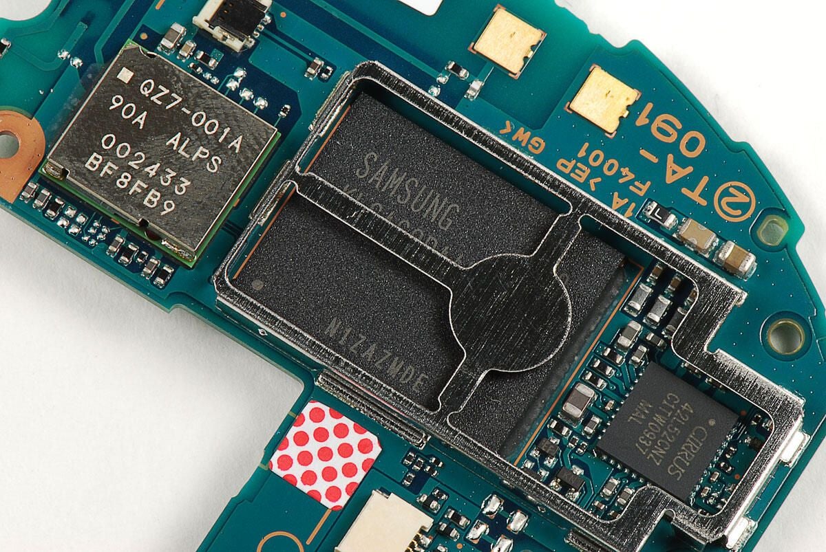
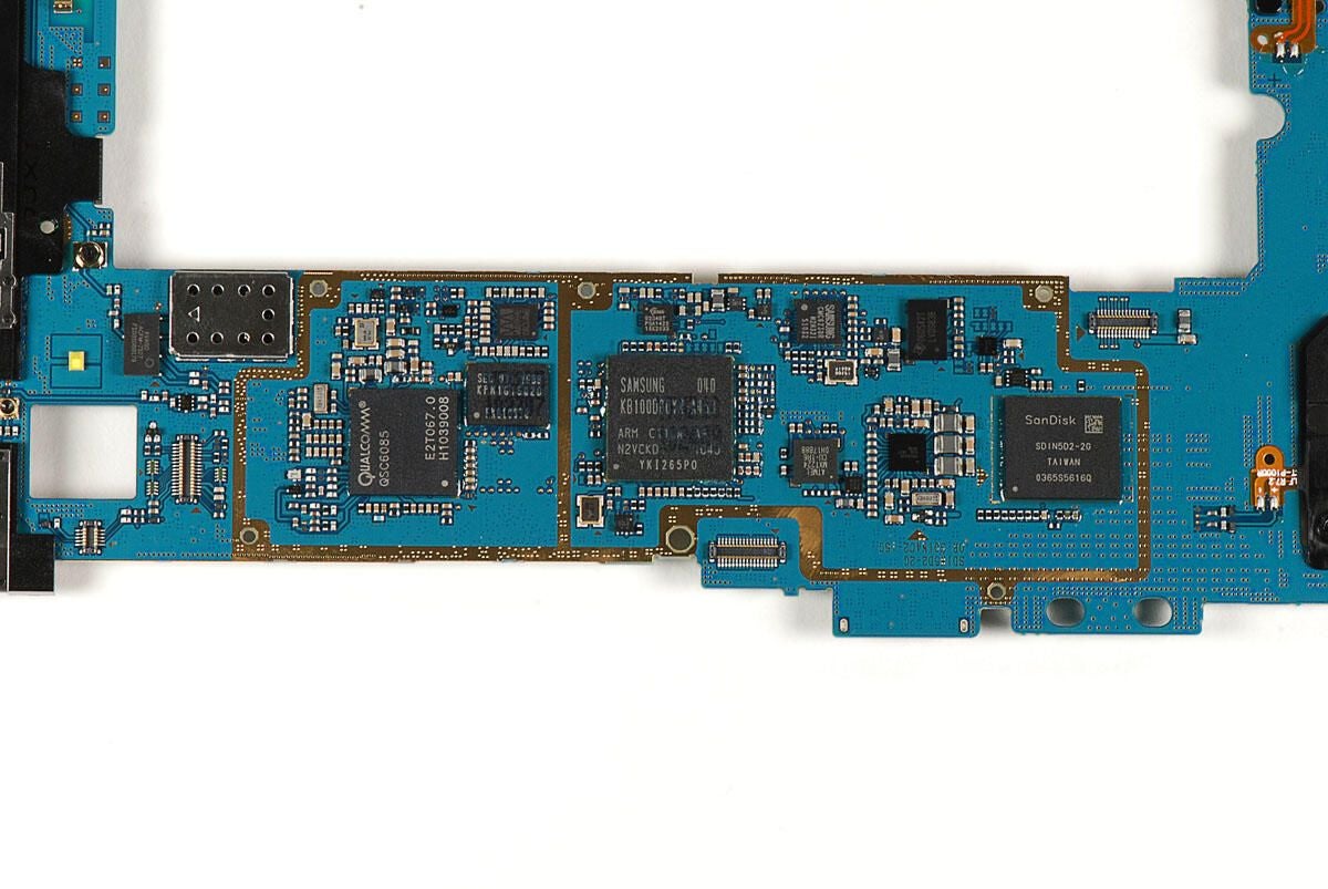
The Samsung 922 flash memory module provides 16GB of storage. The Cirrus Logic 42L52CNZ CFTW0937 MAL is a stereo codec.
Photo by: Bill Detwiler / TechRepublic
Caption by: Bill Detwiler
OKI L86V7657 9405903J
SHARP LR388G1
Photo by: Bill Detwiler / TechRepublic
Caption by: Bill Detwiler
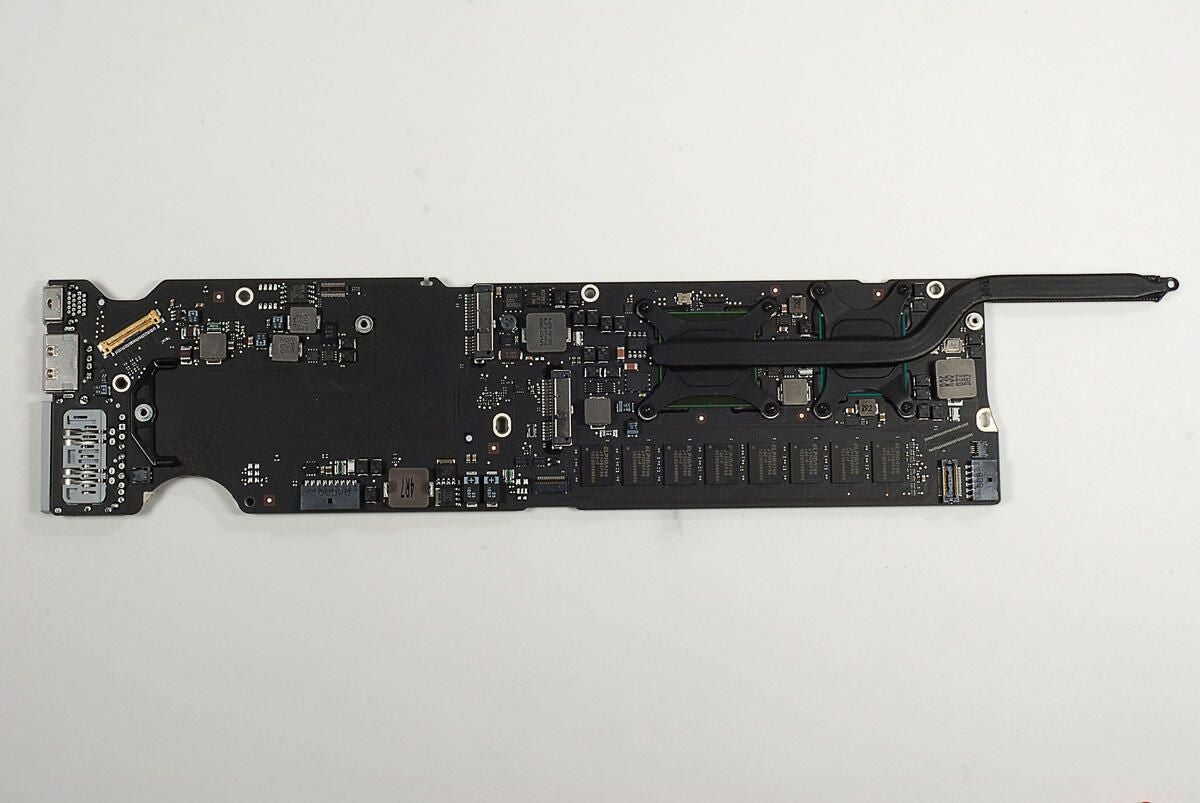
Photo by: Bill Detwiler / TechRepublic
Caption by: Bill Detwiler
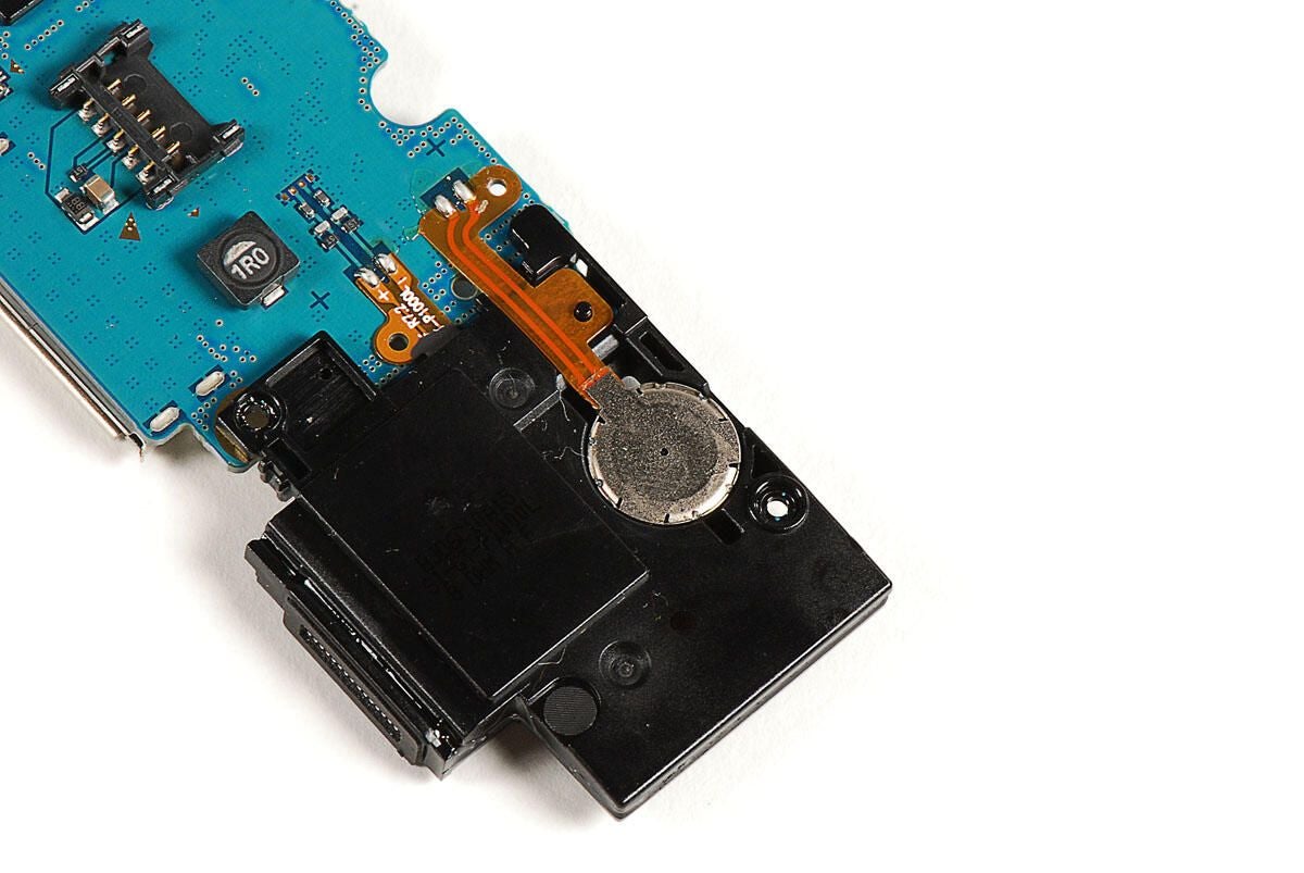
Photo by: Bill Detwiler / TechRepublic
Caption by: Bill Detwiler
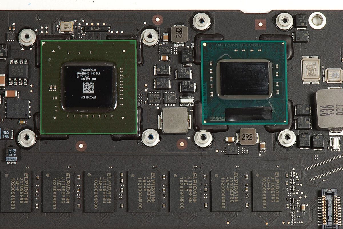
Photo by: Bill Detwiler / TechRepublic
Caption by: Bill Detwiler
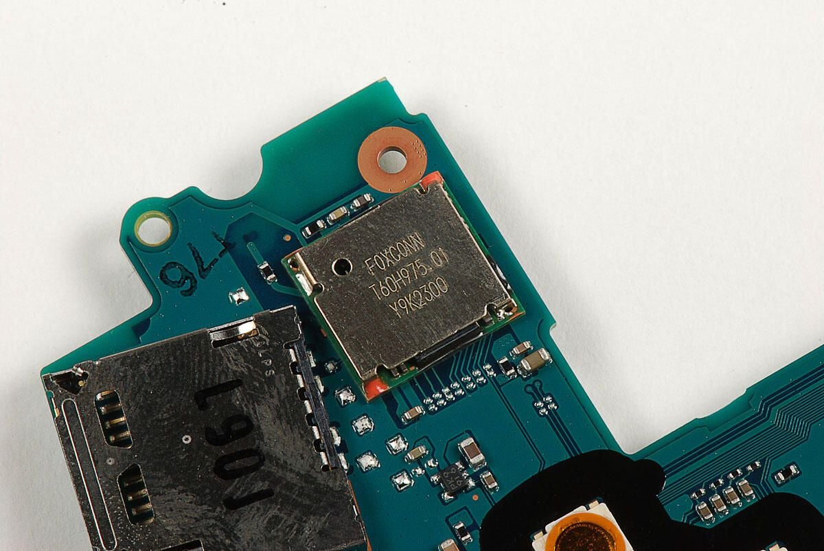
Photo by: Bill Detwiler / TechRepublic
Caption by: Bill Detwiler
SCEI 940EM0E 4053
U2021 9T127
S158 0719
Photo by: Bill Detwiler / TechRepublic
Caption by: Bill Detwiler
Photo by: Bill Detwiler / TechRepublic
Caption by: Bill Detwiler
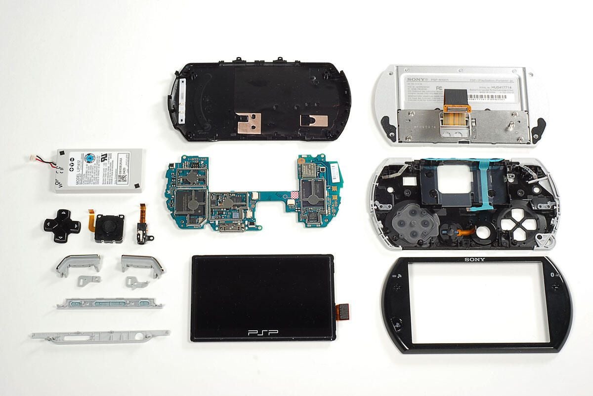
The Sony PSP Go was fairly easy to disassemble. Sony used standard Phillips #00 screws and didn’t solder any of the key components in place. Although disassembling the PSP Go will likely void the warranty, it’s definitely serviceable with the right tools and a little patience.
If you’re thinking about buying a PSP Go for your favorite gadget geek this holiday season, check out our Geek Gift review.
Photo by: Bill Detwiler / TechRepublic
Caption by: Bill Detwiler
Bill Detwiler is the Editor for Technical Content and Ecosystem at Celonis. He is the former Editor in Chief of TechRepublic and previous host of TechRepublic's Dynamic Developer podcast and Cracking Open, CNET and TechRepublic's popular online show. Previously, Bill was an IT manager in the social research and energy industries. He has bachelor's and master's degrees from the University of Louisville, where he has also lectured on computer crime and crime prevention.
