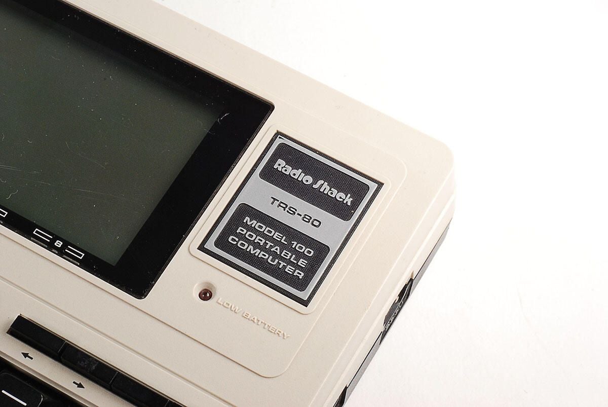
\n\tIn 1983, Tandy released the TRS-80 Model 100 at $999 (US). Adjusted for inflation, the machine would cost $2,187 (US) in 2010.
\n
\n\tThe Model 100 came with an 2.4MHz 8-bit Intel 80C85 CPU (a CMOS verions of the Intel 8085) and 8Kb of base RAM (expandable to 32KB). The machine aslo came with an onboard ROM, which stored pre-installed software, such Basic, Text, Telcom, and Schedule, and Address.
\n
\n\tPhoto by: Bill Detwiler
\n\tCaption by: Bill Detwiler
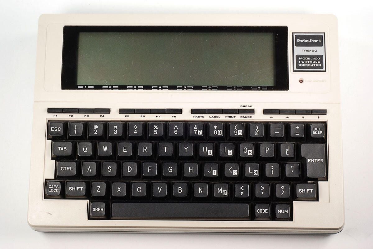
\n\tThe Tandy TRS-80 Model 100 measured 11.8 inches wide by 8.5 inches tall by 2 inches thick. It weighed just over 3 lbs. (with four AA batteries).
\n
\n\tPhoto by: Bill Detwiler
\n\tCaption by: Bill Detwiler
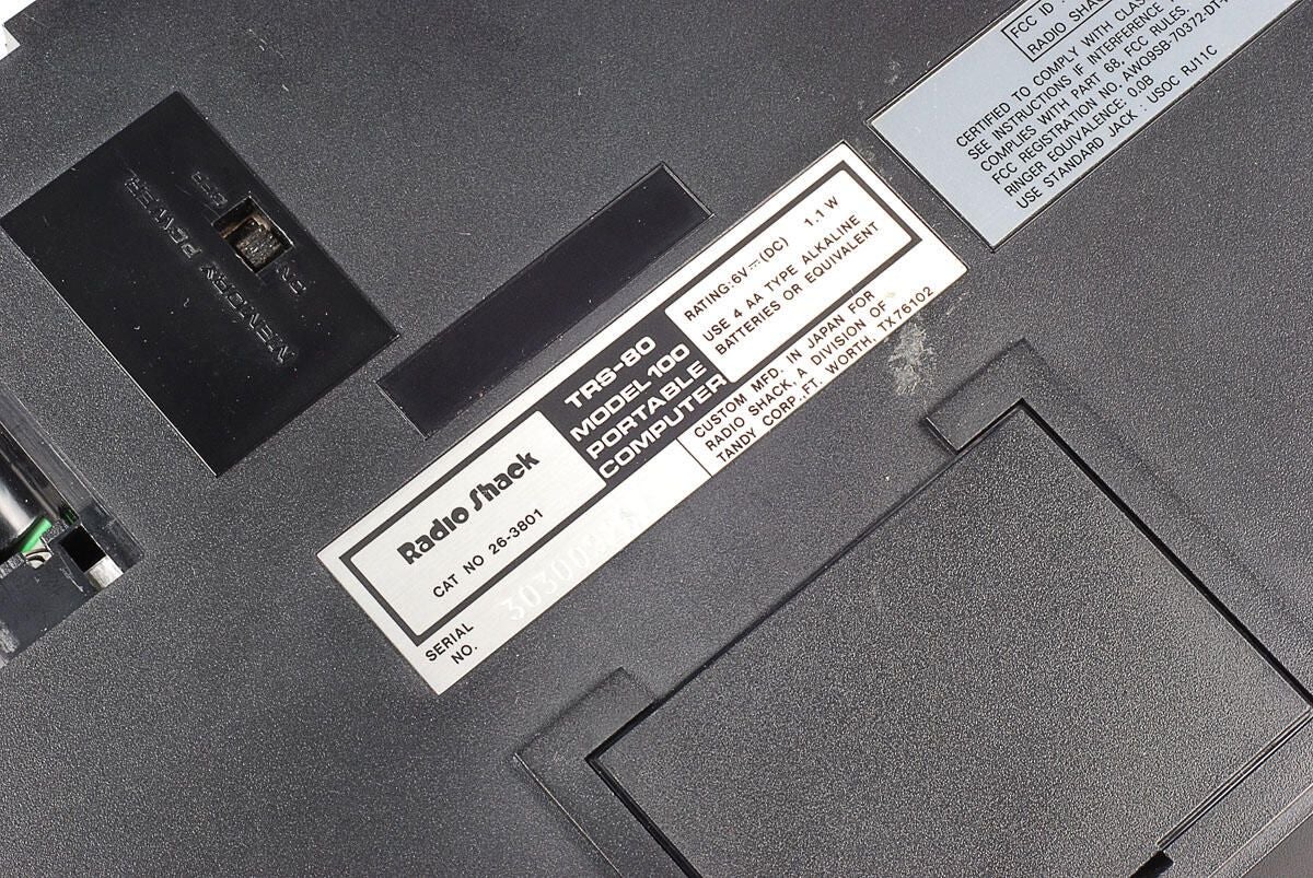
\n\tThis TRS-80 Model 100 was manufactured in Japan by Kyocera for Tandy/Radio Shack.
\n
\n\tPhoto by: Bill Detwiler
\n\tCaption by: Bill Detwiler
\n\tPhoto by: Bill Detwiler
\n\tCaption by: Bill Detwiler
\n\tThe Model 100 has a Memory Power switch. If the 4 AA batteries ever go dead or are removed, the switch let’s you use the CMOS battery to power the memory and store data.
\n
\n\tPhoto by: Bill Detwiler
\n\tCaption by: Bill Detwiler
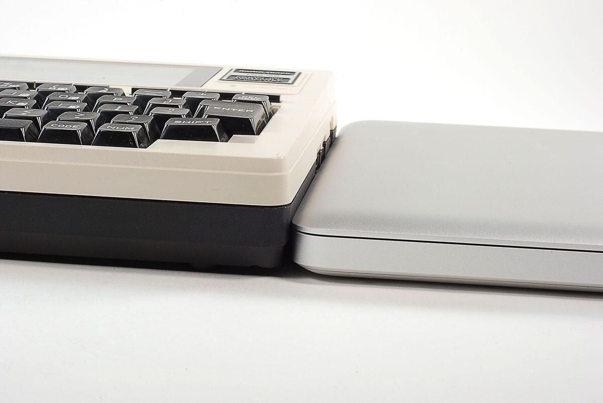
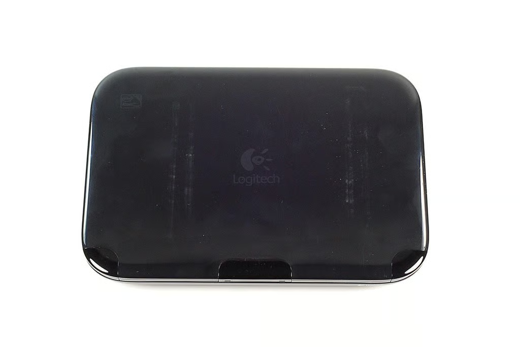
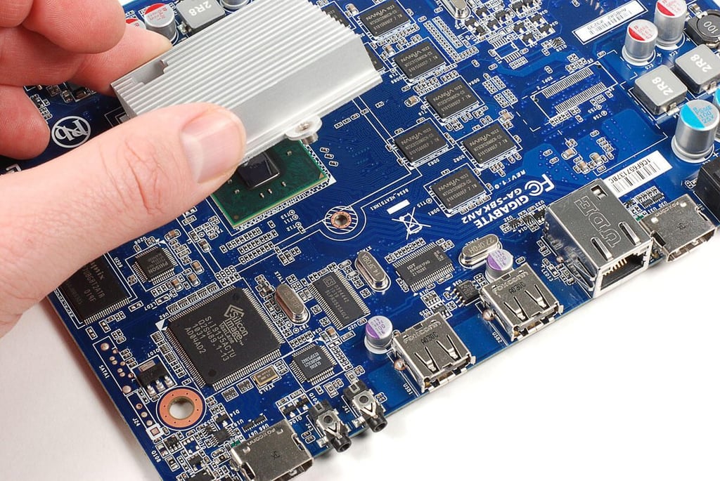
\n\tThis photo shows the Tandy TRS-80 Model 100 next to a 2010 MacBook Pro. It’s interesting to see how much thinner today’s machines are.
\n
\n\tPhoto by: Bill Detwiler
\n\tCaption by: Bill Detwiler
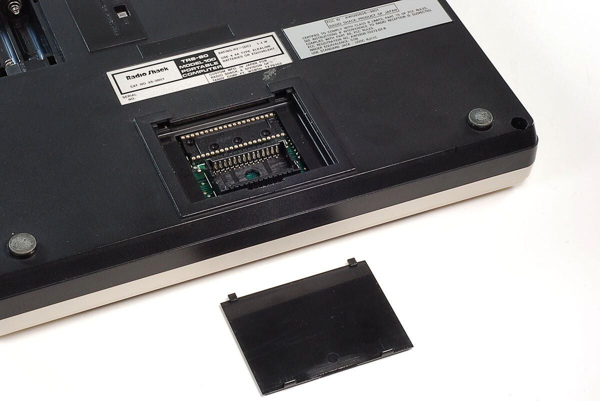
\n\tYou could add programs to the TRS-80 Model 100 through preprogrammed ROMs, which could be installed here.
\n
\n\tPhoto by: Bill Detwiler
\n\tCaption by: Bill Detwiler
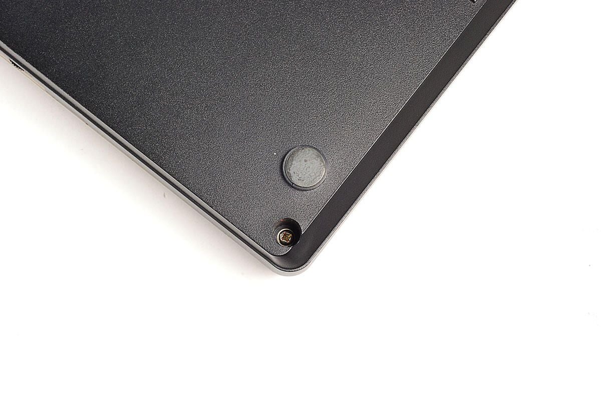
\n\tUnlike many of today’s portable computers which use special tamper-resistant screws, the TRS-80 Model 100 uses standard Phillips screws. There are four external screws that need to be removed.
\n
\n\tPhoto by: Bill Detwiler
\n\tCaption by: Bill Detwiler
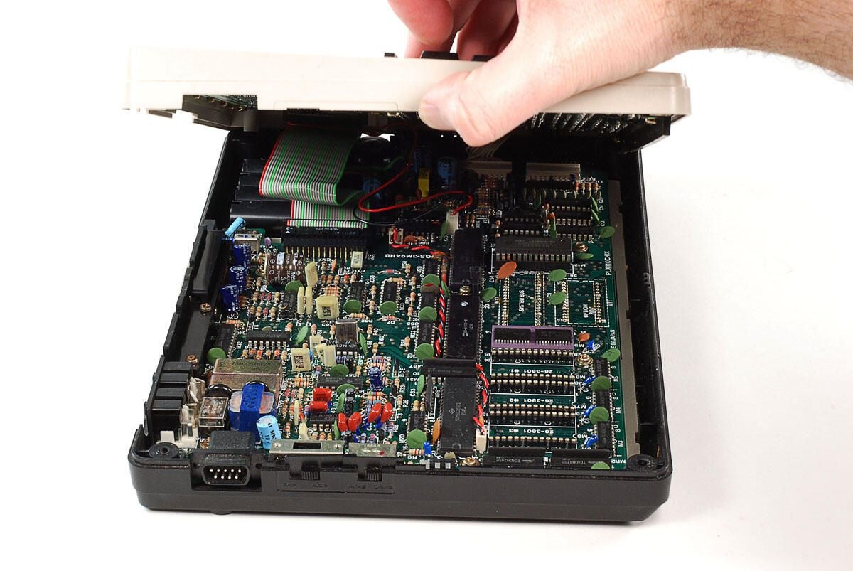
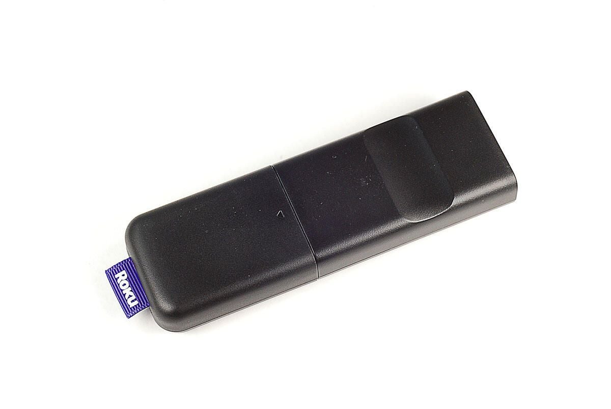
\n\tWith the four external screws removed, you can lifting the top half of the case away from the bottom. There are several cables that connect the two halves, so lift up from the machine’s left side (where the bar code reader port is).
\n
\n\tPhoto by: Bill Detwiler
\n\tCaption by: Bill Detwiler
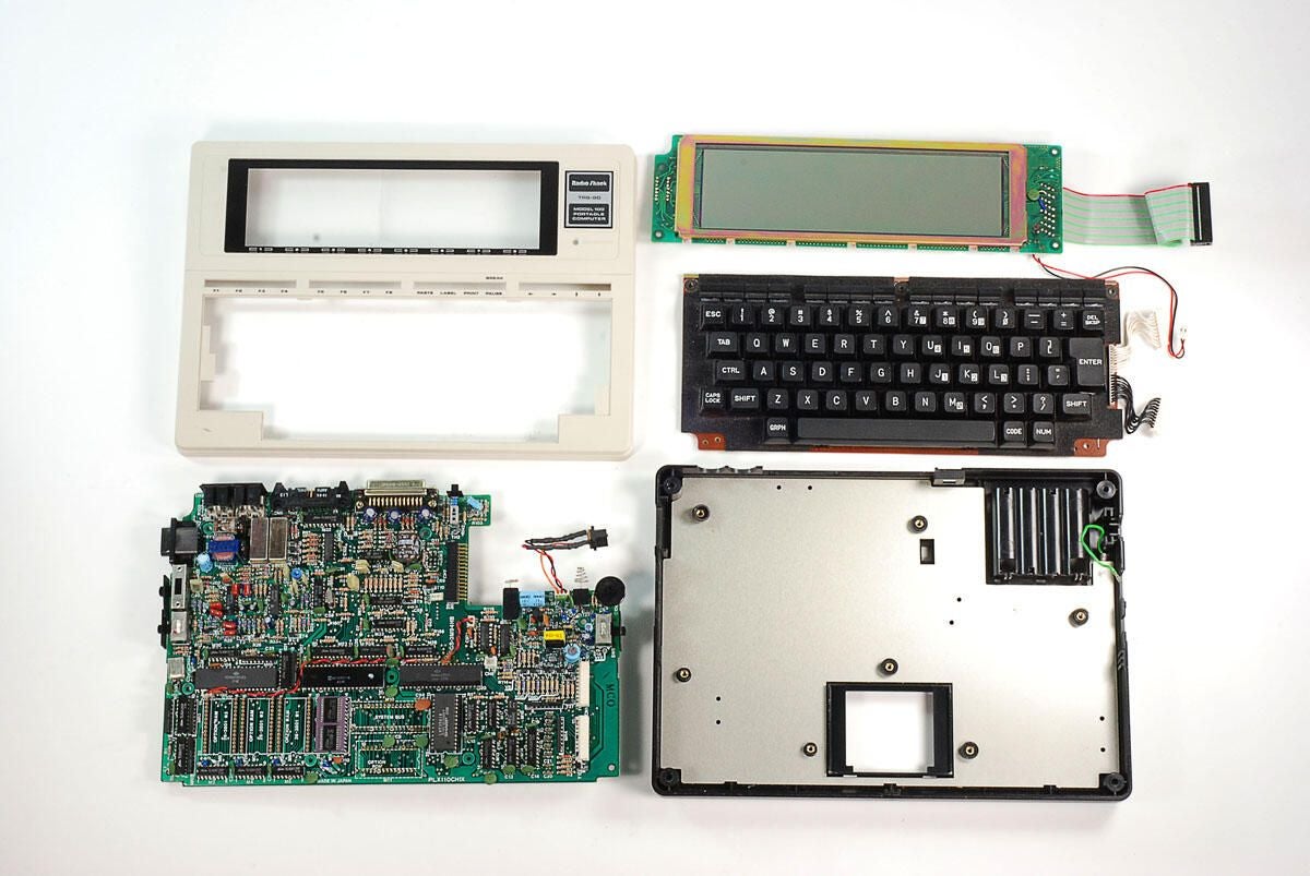
\n\tLuckily, the internal cables on the TRS-80 Model 100 are long enough to lay both halves next to each other.
\n
\n\tThe motherboard and ports remain in the lower half of the case, while the display, keyboard, and internal speaker are attached to the top.
\n
\n\tPhoto by: Bill Detwiler
\n\tCaption by: Bill Detwiler
\n\tYou’ll need to disconnect the cables for the display, speaker, and keyboard before separating the two halves of the TRS-80 Model 100.
\n
\n\tPhoto by: Bill Detwiler
\n\tCaption by: Bill Detwiler
\n\tThe display, keyboard, and speaker are attached to the top half of the the TRS-80 Model 100’s case.
\n
\n\tPhoto by: Bill Detwiler
\n\tCaption by: Bill Detwiler
\n\tFive Phillips screws hold the TRS-80 Model 100’s keyboard in place.
\n
\n\tPhoto by: Bill Detwiler
\n\tCaption by: Bill Detwiler
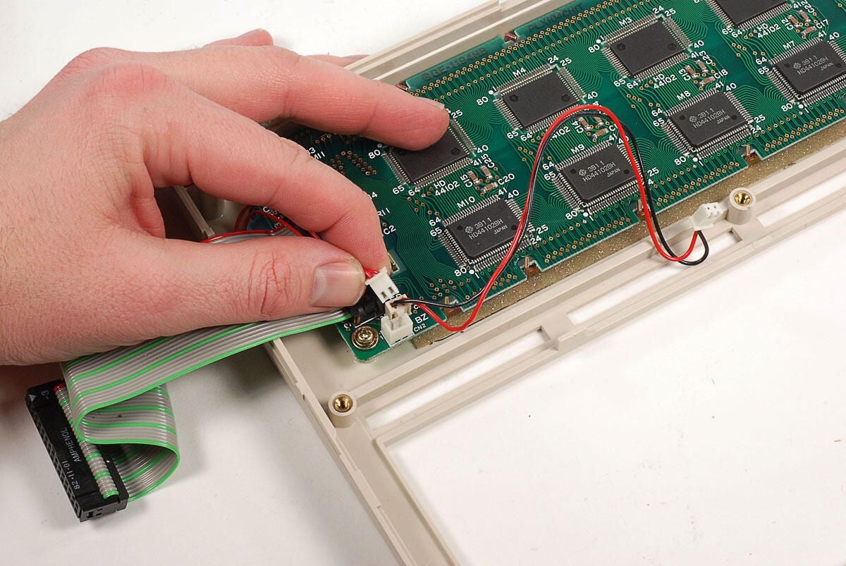
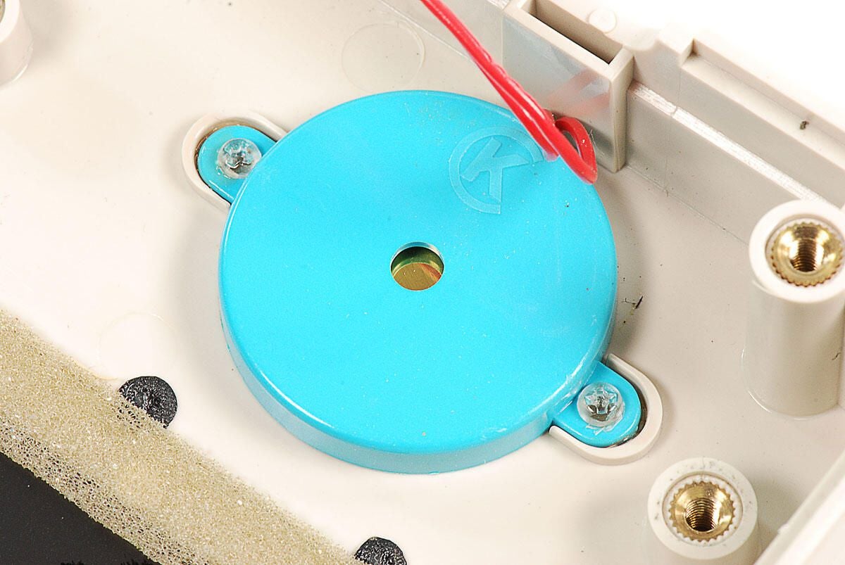
\n\tThe TRS-80 Model 100’s internal speaker is connected to the display’s PCB with a thin wire. You’ll need to disconnect this wire before removing the display assembly.
\n
\n\tPhoto by: Bill Detwiler
\n\tCaption by: Bill Detwiler
\n\tFour Phillips screws hold the TRS-80 Model 100’s LCD display assembly to the upper half of the case.
\n
\n\tPhoto by: Bill Detwiler
\n\tCaption by: Bill Detwiler
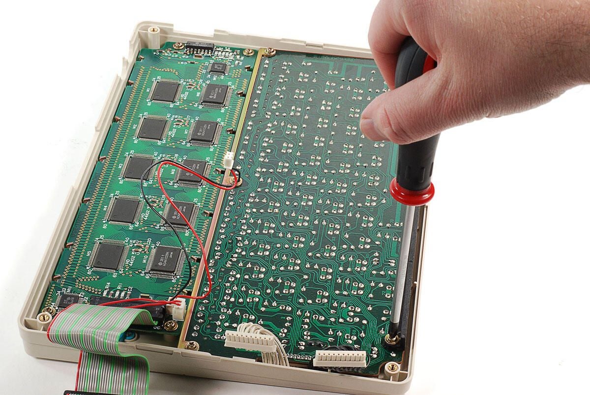
\n\tWith the screws removed, you can lift the Model 100’s display screen and PCB away from the case.
\n
\n\tPhoto by: Bill Detwiler
\n\tCaption by: Bill Detwiler
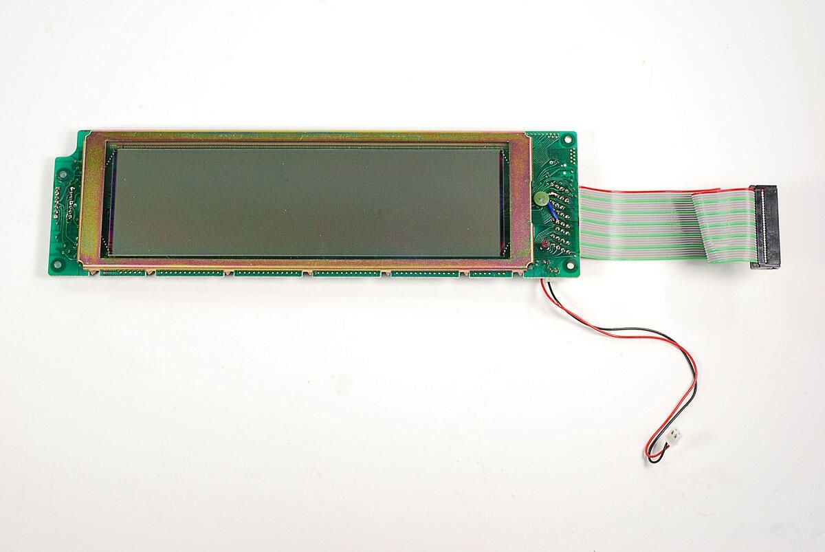
\n\tThe TRS-80 Model 100’s monochrome LCD display provides a resolution of 240 x 64 pixels and can show eight lines of text. The screen was not backlit.
\n
\n\tPhoto by: Bill Detwiler
\n\tCaption by: Bill Detwiler
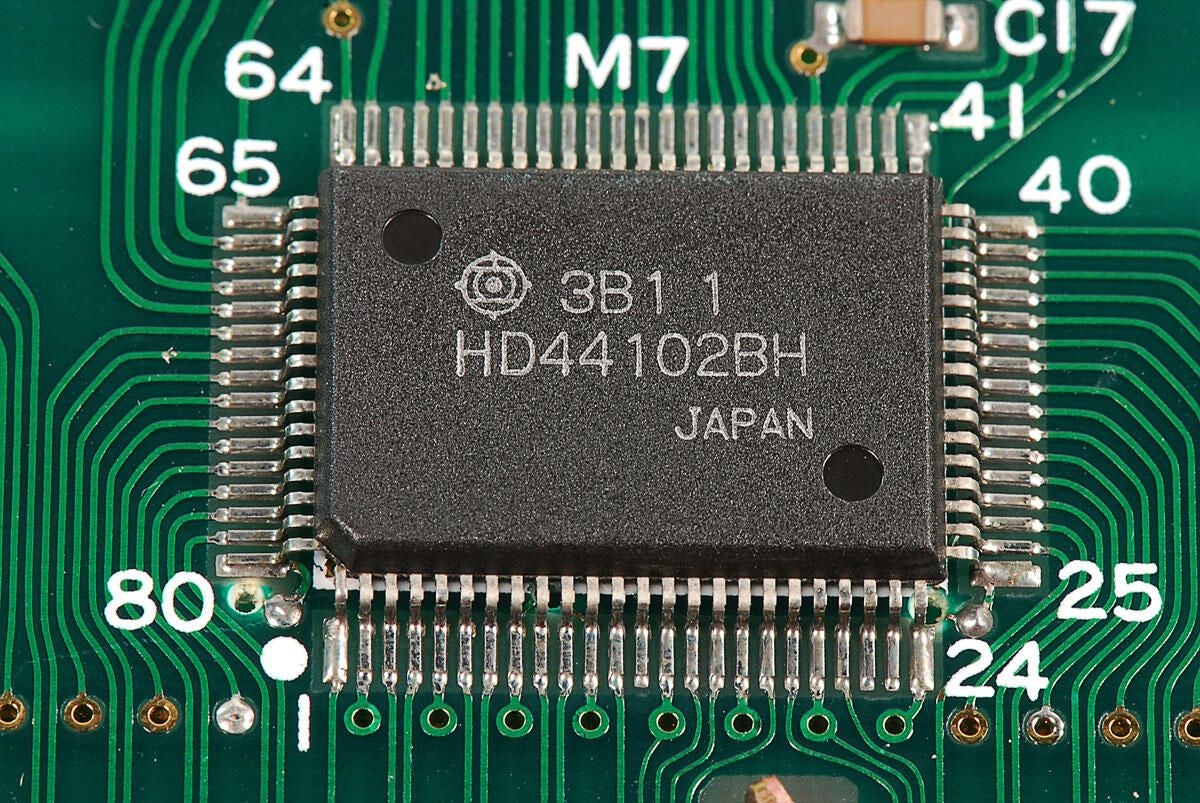
\n\tThere are several large Hitachi HD44102 Dot Matrix Liquid Crystal Graphic Display Column Driver chips mounted to the back of the display’s PCB.
\n
\n\tPhoto by: Bill Detwiler
\n\tCaption by: Bill Detwiler
\n\tAlong with the HD44102 chips, there are two Hitachi HD44103 Dot Matrix Liquid Crystal Graphic Display Common Driver chips mounted to the display’s PCB.
\n
\n\tAccording to documentation on Alldatasheet.com, the smaller HD44103 chips generate the timing signals required for display with their internal oscillator and supply them to the HD44102 column driver to control the display.
\n
\n\tPhoto by: Bill Detwiler
\n\tCaption by: Bill Detwiler
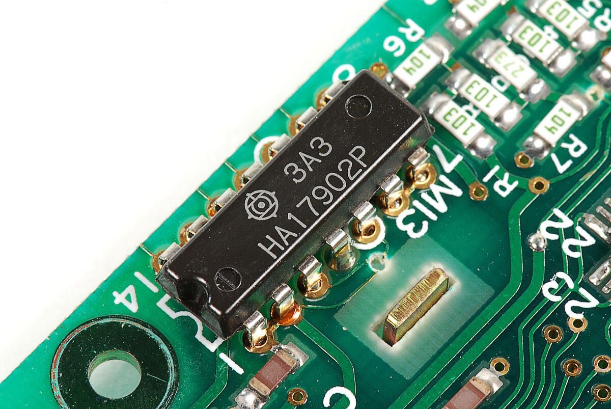
\n\tA single Hitachi HA17902 Quad Operational Amplifier is also mounted on the display’s PCB.
\n
\n\tPhoto by: Bill Detwiler
\n\tCaption by: Bill Detwiler
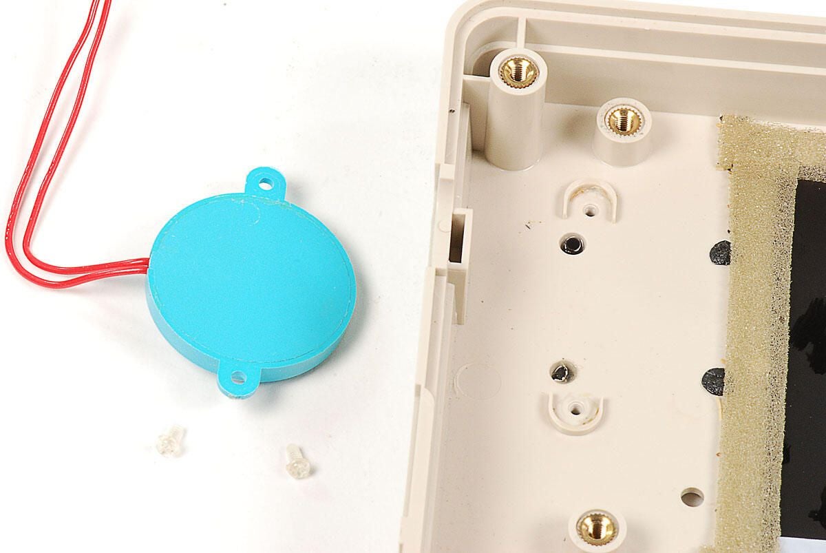
\n\tThe TRS-80 Model 100’s internal speaker is held to the frame with clear, plastic screws. I used a #00 Phillips screw driver bit to remove them.
\n
\n\tPhoto by: Bill Detwiler
\n\tCaption by: Bill Detwiler
\n\tPhoto by: Bill Detwiler
\n\tCaption by: Bill Detwiler
\n\tWith the upper case completely disassembled, let’s turn out attention back to the lower half of the TRS-80 Model 100.
\n
\n\tPhoto by: Bill Detwiler
\n\tCaption by: Bill Detwiler
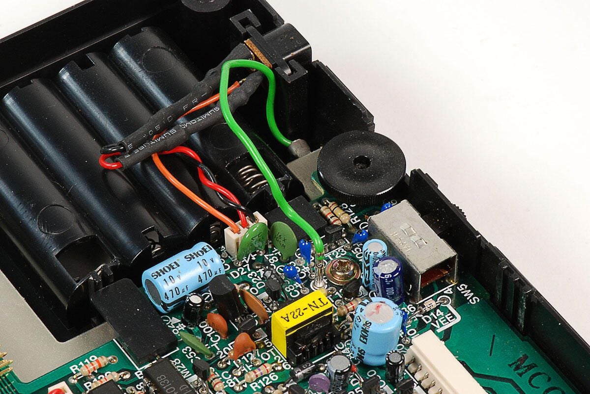
\n\tThe first step in removing the TRS-80 Model 100’s motherboard from the lower half of the case is to disconnect the green ground wire.
\n
\n\tPhoto by: Bill Detwiler
\n\tCaption by: Bill Detwiler
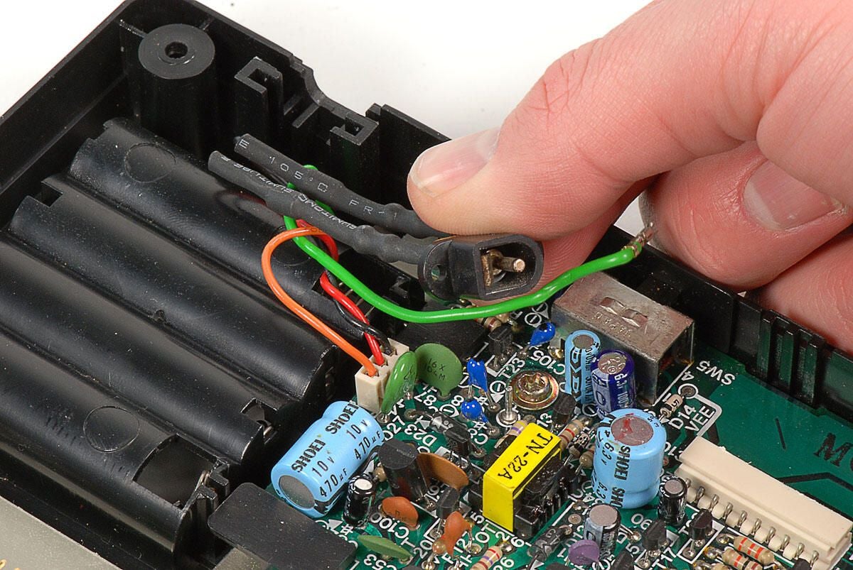
\n\tAfter disconneting the ground wire, you can lift the power connecter away from its slot in the case. You do not need to disconnect its wires from the motherboard.
\n
\n\tPhoto by: Bill Detwiler
\n\tCaption by: Bill Detwiler
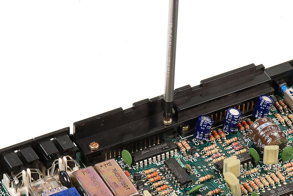
\n\tAlthough it’s not necessary to remove the plastic bar that covers the serial and printer ports, I went ahead and did so.
\n
\n\tPhoto by: Bill Detwiler
\n\tCaption by: Bill Detwiler
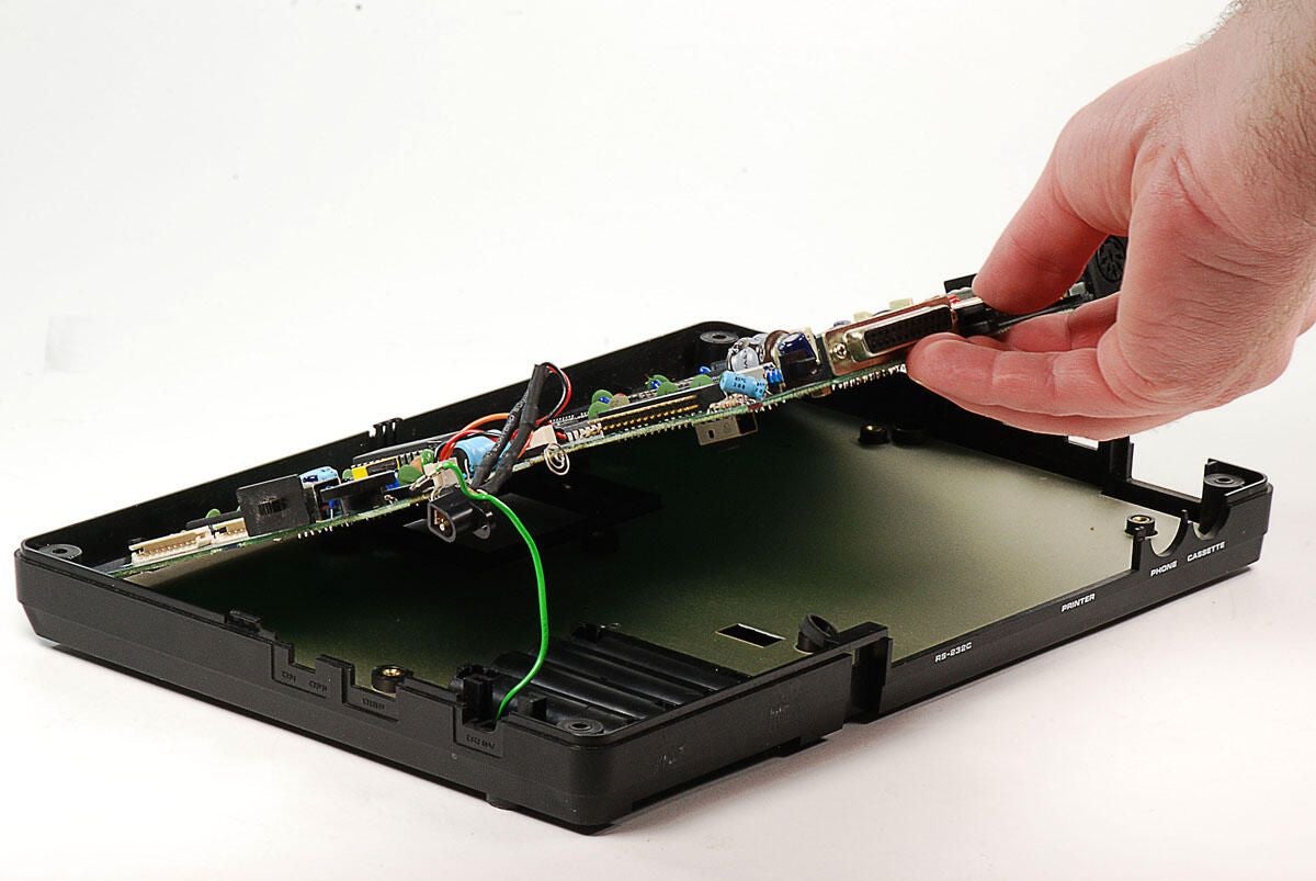
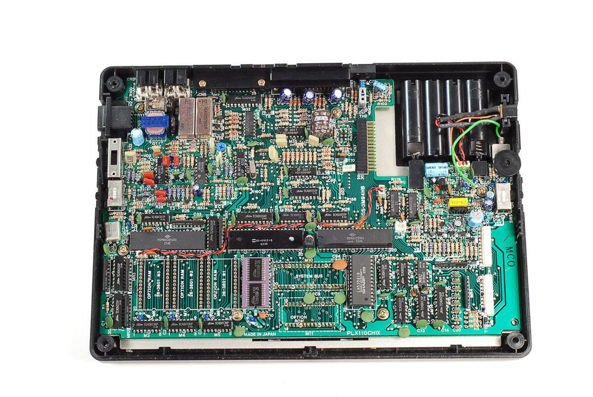
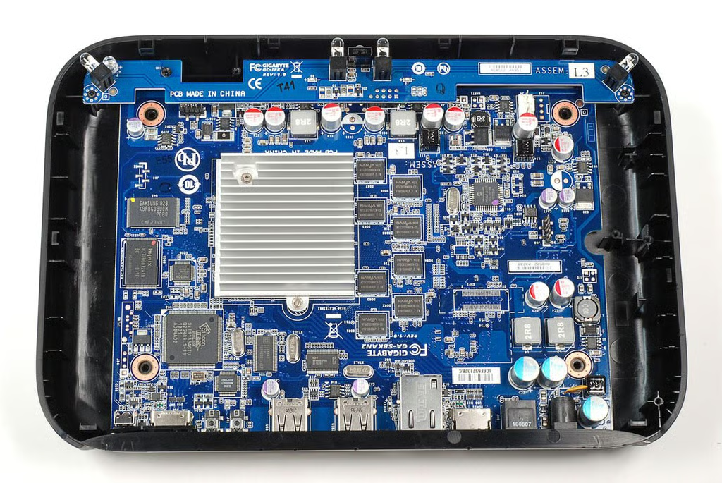
\n\tWith the screws removed, you can lift the TRS-80 Model 100’s motherboard away from the lower half of the case.
\n
\n\tPhoto by: Bill Detwiler
\n\tCaption by: Bill Detwiler
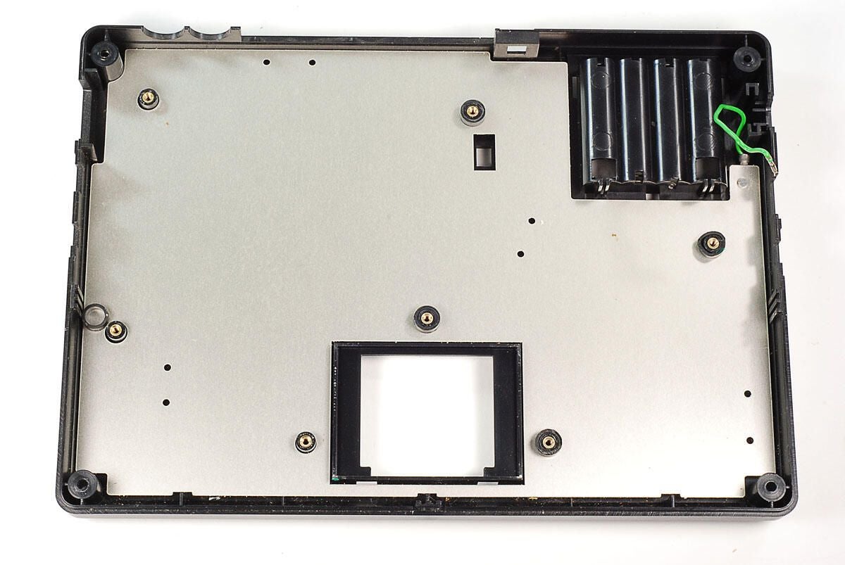
\n\tThere’s nothing left in the case but a thin metal shield and attached ground wire.
\n
\n\tPhoto by: Bill Detwiler
\n\tCaption by: Bill Detwiler
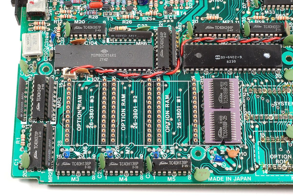
\n\tThe main points of interest in this corner of the motherboard are the OKI MSM80C85ARS processor (upper left), D3-6402-9 UART chip (upper right), and Toshiba TC5518BF-25 RAM (lower right).
\n
\n\tPhoto by: Bill Detwiler
\n\tCaption by: Bill Detwiler
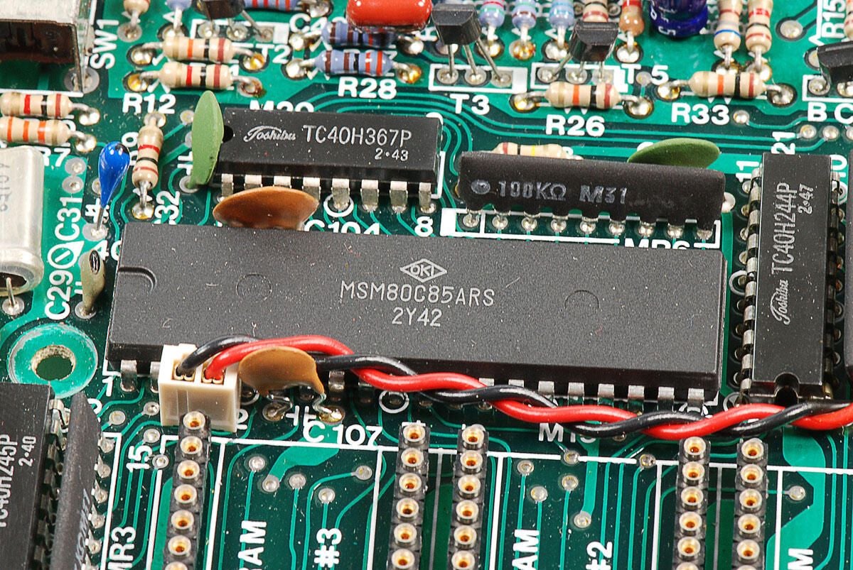
\n\tThis Model 100’s Intel 2.4MHz 80C85 CPU was manufactured by OKI and has markings MSM80C85ARS.
\n
\n\tPhoto by: Bill Detwiler
\n\tCaption by: Bill Detwiler
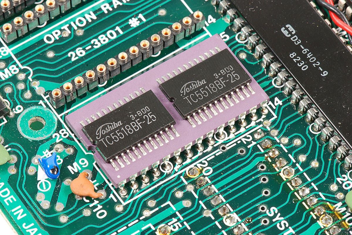
\n\tToshiba TC5518BF-25 RAM
\n
\n\tThis unit has 8Kb of RAM.
\n
\n\tPhoto by: Bill Detwiler
\n\tCaption by: Bill Detwiler
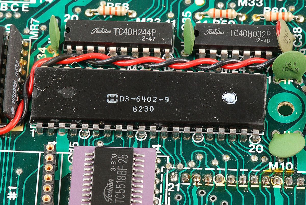
\n\tThis D3-6402-9 UART chip drives the TRS-80 Model 100’s RS232 serial port.
\n
\n\tPhoto by: Bill Detwiler
\n\tCaption by: Bill Detwiler
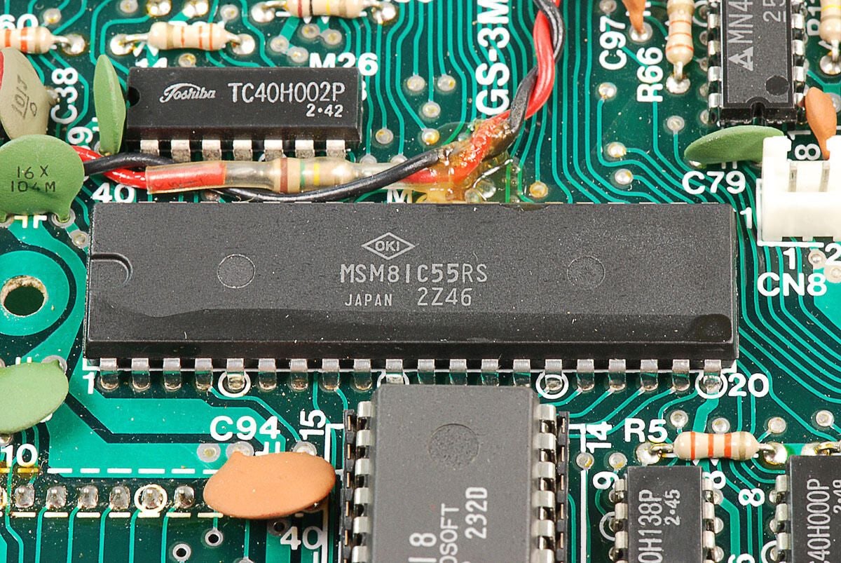
\n\tThis MC81C85RS I/O controller chip drives the keyboard, parallel printer, speaker, clock, and LCD.
\n
\n\tPhoto by: Bill Detwiler
\n\tCaption by: Bill Detwiler
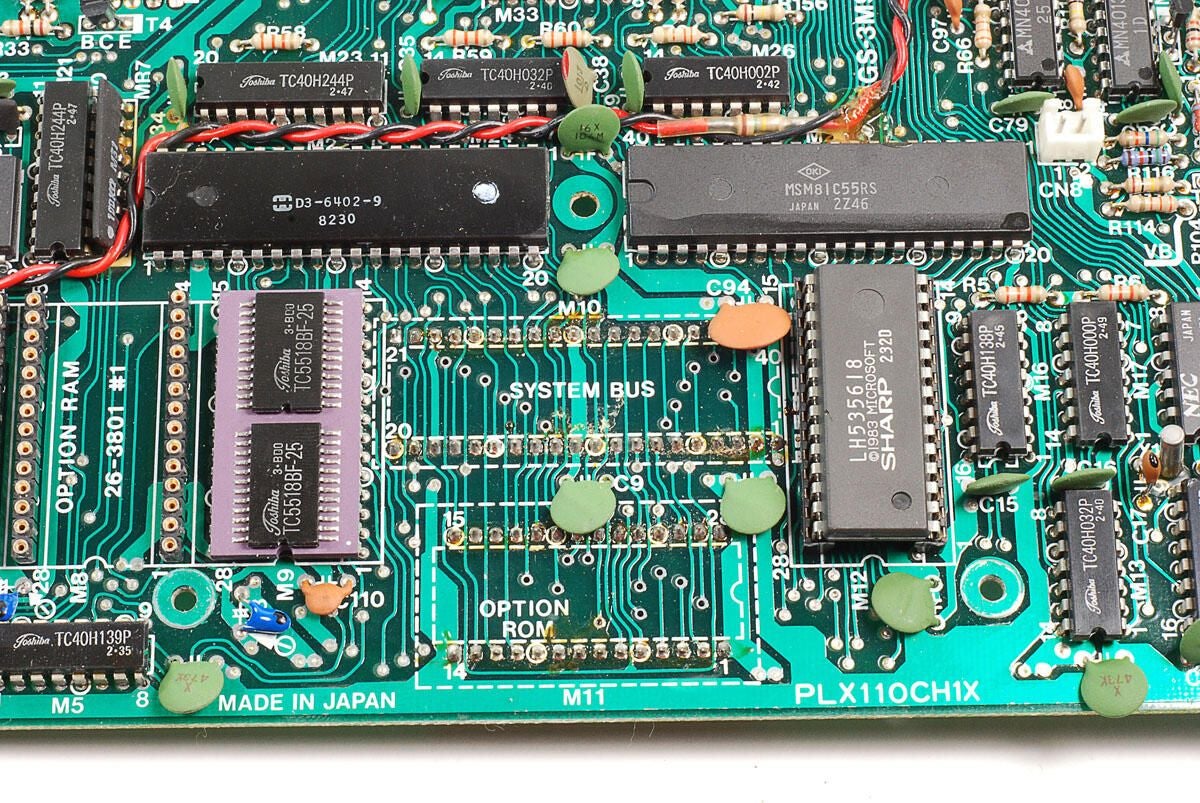
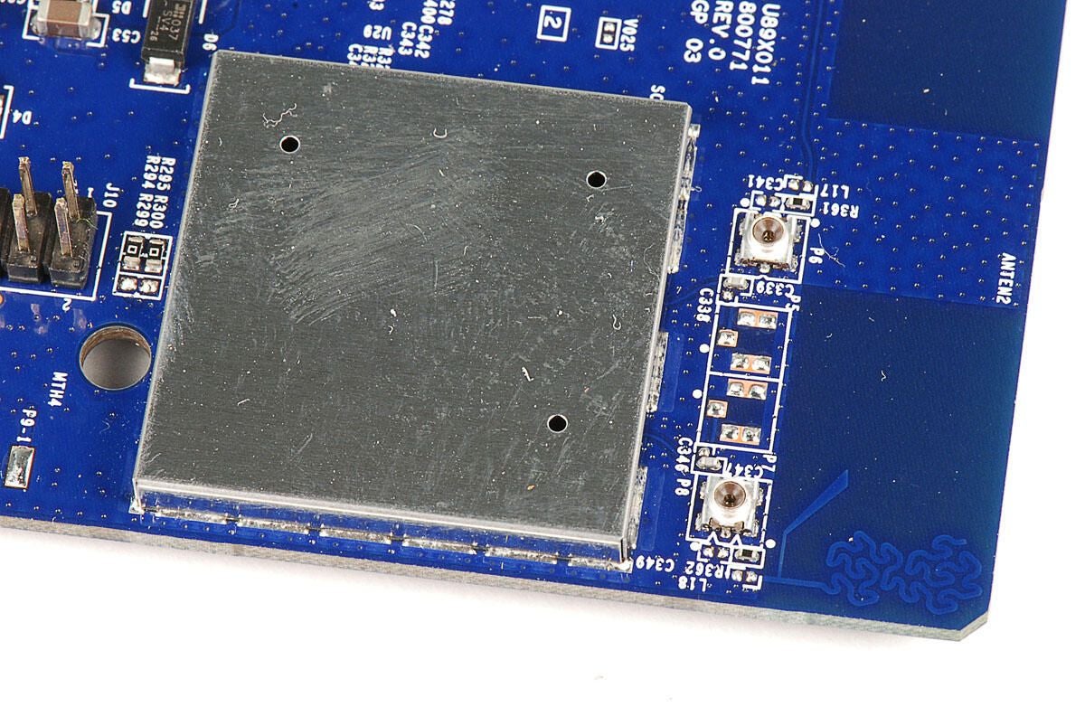
\n\tBelow the serial connector and I/O controller chips and to the right of the RAM chip, there are solder points for the option ROM sockets, which are mounted on the underside of the motherboard.
\n
\n\tPhoto by: Bill Detwiler
\n\tCaption by: Bill Detwiler
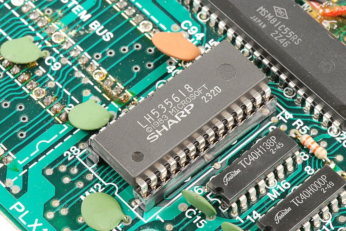
\n\tThis Sharp LH535618 ROM chip contains the TRS-80 Model 100’s built-in software, such as BASIC.
\n
\n\tPhoto by: Bill Detwiler
\n\tCaption by: Bill Detwiler
\n\tThere are many different Toshiba TC40H chips mounted around the motherboard, which are used for the keyboard.
\n
\n\tPhoto by: Bill Detwiler
\n\tCaption by: Bill Detwiler
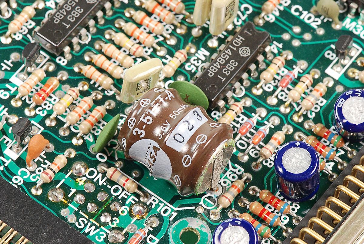
\n\tAs noted eariier, this 3.6V rechargeable battery would power the information stored in memory if the four AA batteries were removed or went dead.
\n
\n\tPhoto by: Bill Detwiler
\n\tCaption by: Bill Detwiler
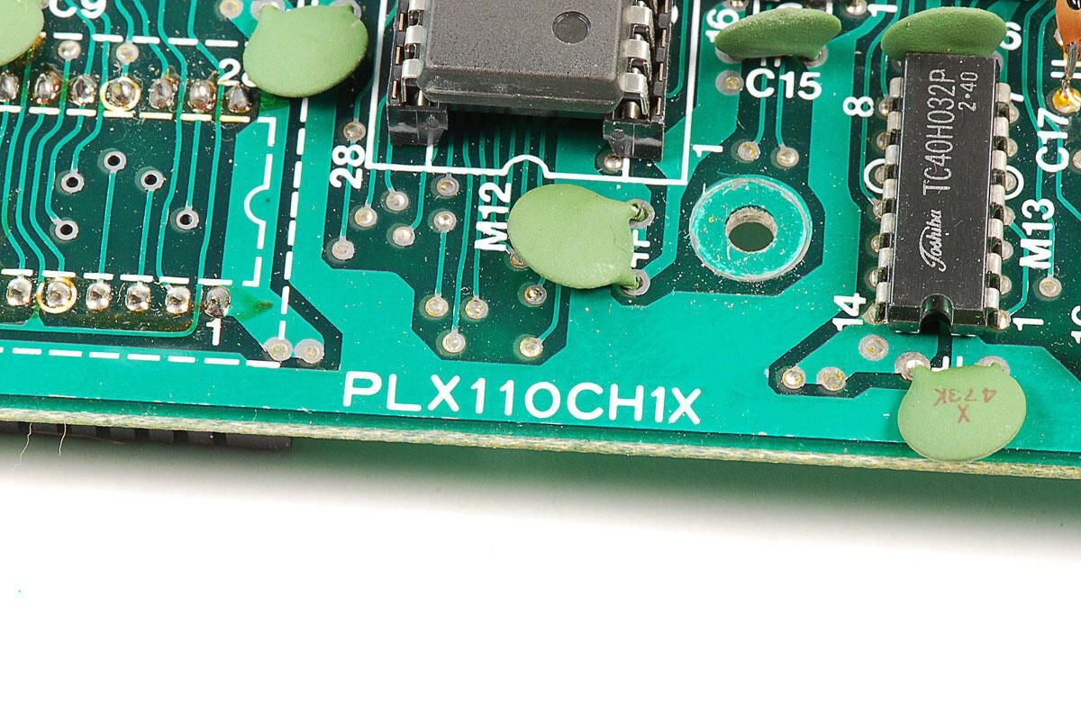
\n\tThe motherboard on this TRS-80 Model 100 has the marking PLX100CH1X.
\n
\n\tPhoto by: Bill Detwiler
\n\tCaption by: Bill Detwiler
\n\tThanks to TRS-80 Model 100’s standard Phillips screws and sturdy construction, cracking it open was an simple and enjoyable process. It’s also interesting to see how the internal components of notebook computers have change in 28 years.
\n
\n\tYou can find out more about the Tandy TRS-80 Model 100 with the following links:
\n
\n\t
\n
\n
\n\tPhoto by: Bill Detwiler
\n\tCaption by: Bill Detwiler
Bill Detwiler is the Editor for Technical Content and Ecosystem at Celonis. He is the former Editor in Chief of TechRepublic and previous host of TechRepublic's Dynamic Developer podcast and Cracking Open, CNET and TechRepublic's popular online show. Previously, Bill was an IT manager in the social research and energy industries. He has bachelor's and master's degrees from the University of Louisville, where he has also lectured on computer crime and crime prevention.


