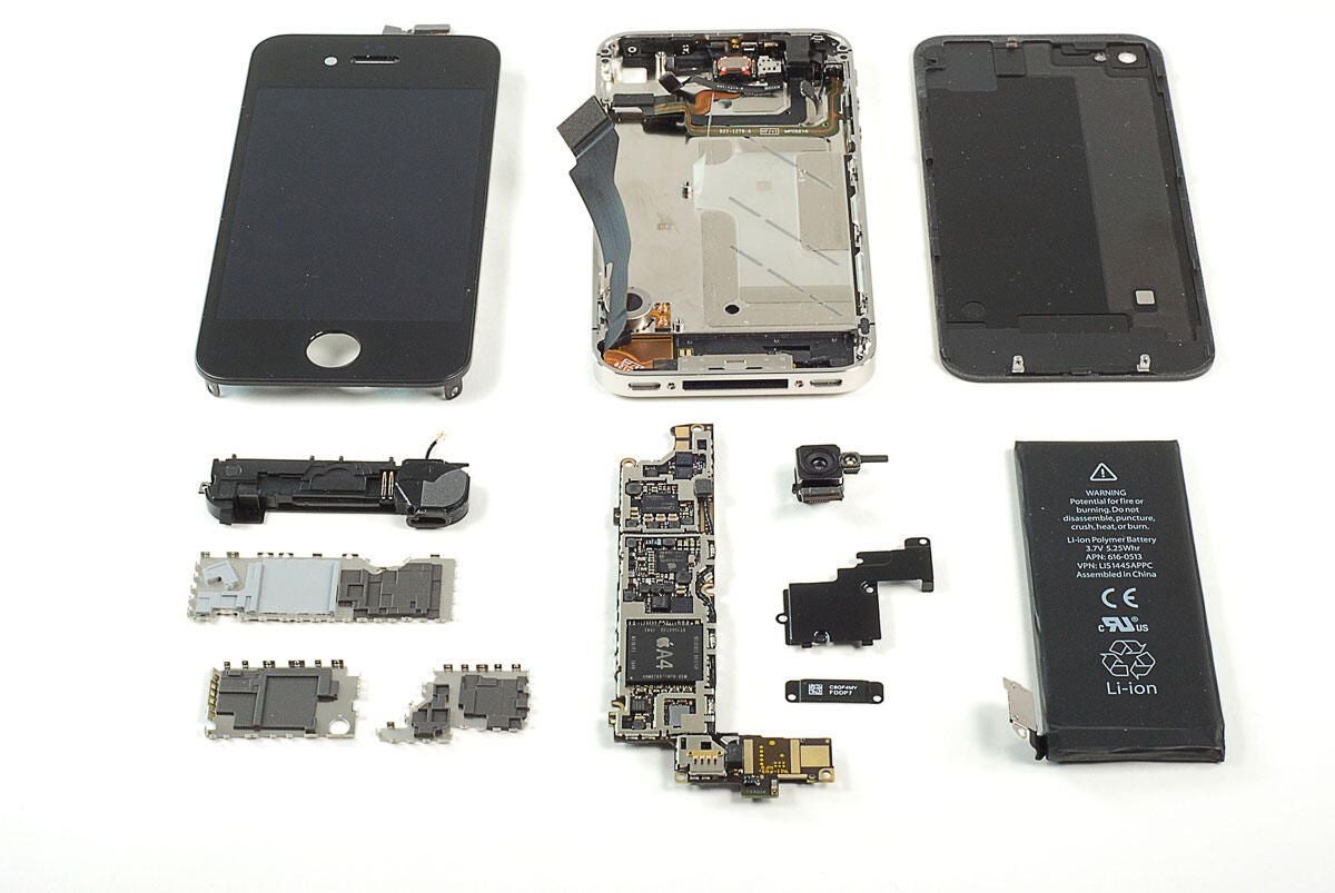
\n\tAfter four years of being exclusive to AT&T (in the US), the Apple iPhone is now available on Verizon. And like the original iPhone 4, we couldn’t wait to get our hands on the Verizon model and crack it open. Follow along as we take a peak at the hardware inside Apple’s CDMA iPhone 4 for Verizon.
\n\t
\n\tPhoto by: Bill Detwiler / TechRepublic
\n\tCaption by: Bill Detwiler
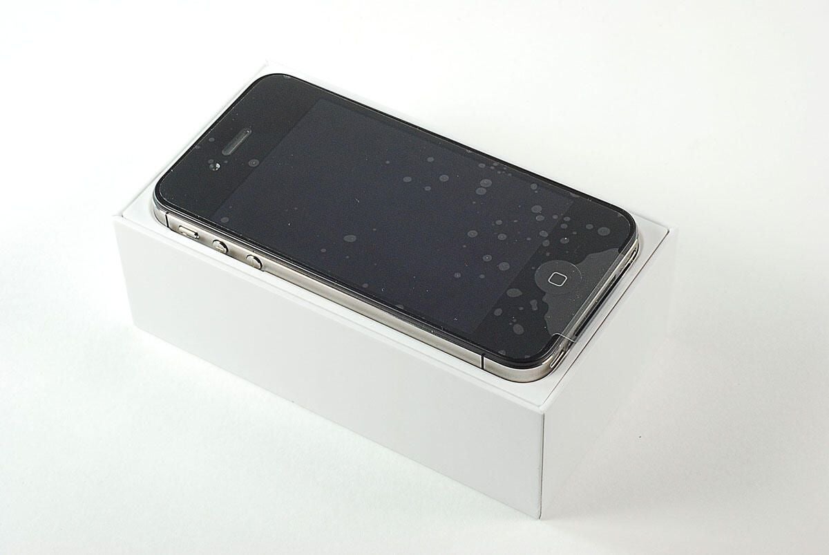
\n\tOpening the box, we find the Verizon iPhone 4.
\n
\n\tPhoto by: Bill Detwiler / TechRepublic
\n\tCaption by: Bill Detwiler
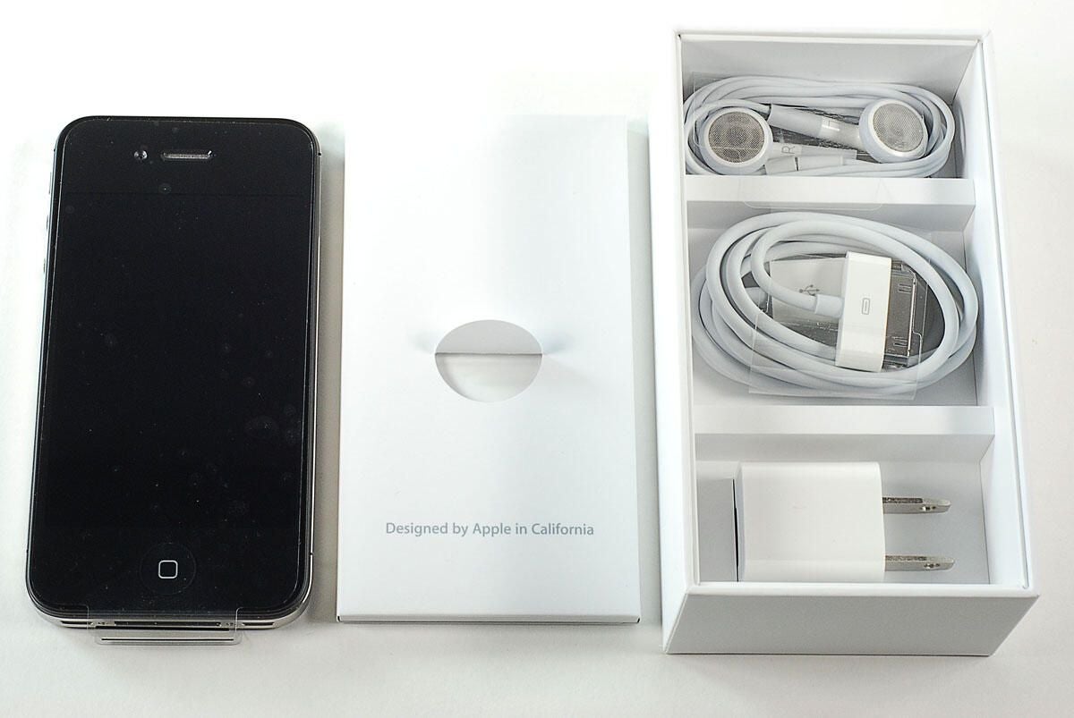
\n\tAs with the original iPhone 4, inside the Verizon iPhone 4’s box are the device, headphones, AC power adapter, 30-pin connector cable, and product documentation.
\n\t
\n\tPhoto by: Bill Detwiler / TechRepublic
\n\tCaption by: Bill Detwiler
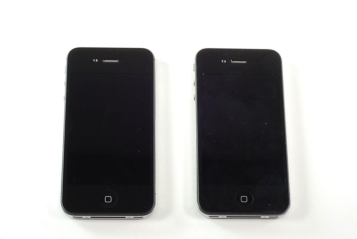
\n\tThe Verizon iPhone 4 is on the left and the AT&T iPhone 4 is on the right. From the front, I can’t tell the difference. Can you?
\n\t
\n\tPhoto by: Bill Detwiler / TechRepublic
\n\tCaption by: Bill Detwiler

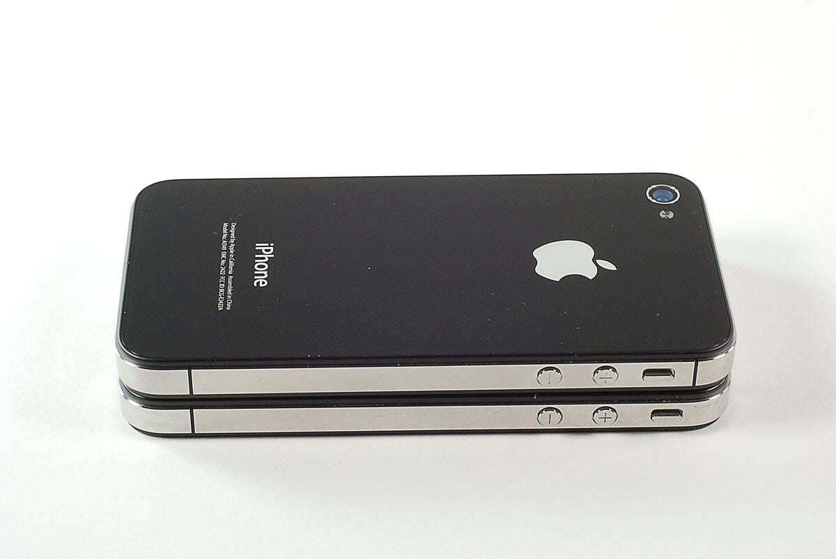
\n\tFrom the back, you can tell the Verizon iPhone 4 (left) from the AT&T iPhone 4 (right) by looking at the model number–A1349 for the Verizon device and A1322 for the AT&T phone.
\n\t
\n\tPhoto by: Bill Detwiler / TechRepublic
\n\tCaption by: Bill Detwiler
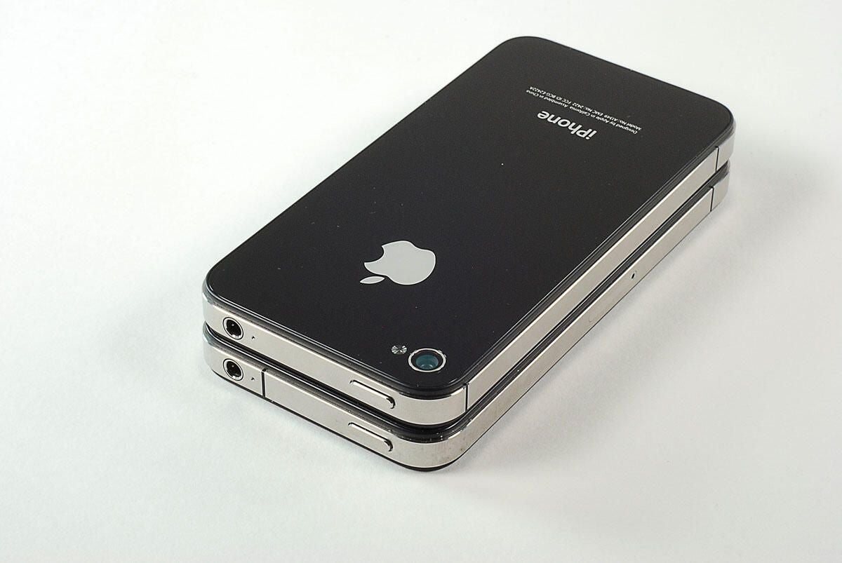
\n\tLooking at the left edges of each device, we can see another external difference–the antenna design. The iPhone 4’s metal frame also serves as the phone’s antenna. The Verizon iPhone 4 (top) has a slightly different antenna configuration. Notice the black space to the right of the Verizon device’s vibrate toggle switch.
\n\t
\n\tPhoto by: Bill Detwiler / TechRepublic
\n\tCaption by: Bill Detwiler
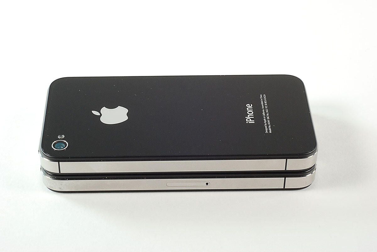
\n\tLooking at the right edge of each phone, you’ll also notice the absense of a SIM card slot on the Verizon iPhone 4 (top).
\n\t
\n\tPhoto by: Bill Detwiler / TechRepublic
\n\tCaption by: Bill Detwiler
\n\tNow that we’ve looked at the external differences, let’s get down to cracking the Verizon iPhone 4 open.
\n\t
\n\tPhoto by: Bill Detwiler / TechRepublic
\n\tCaption by: Bill Detwiler
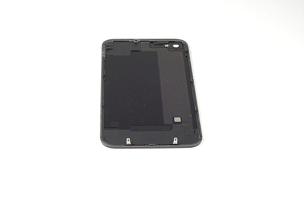
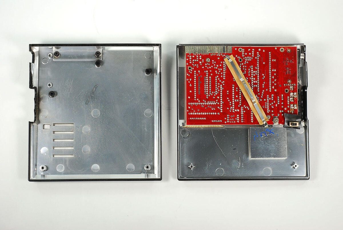
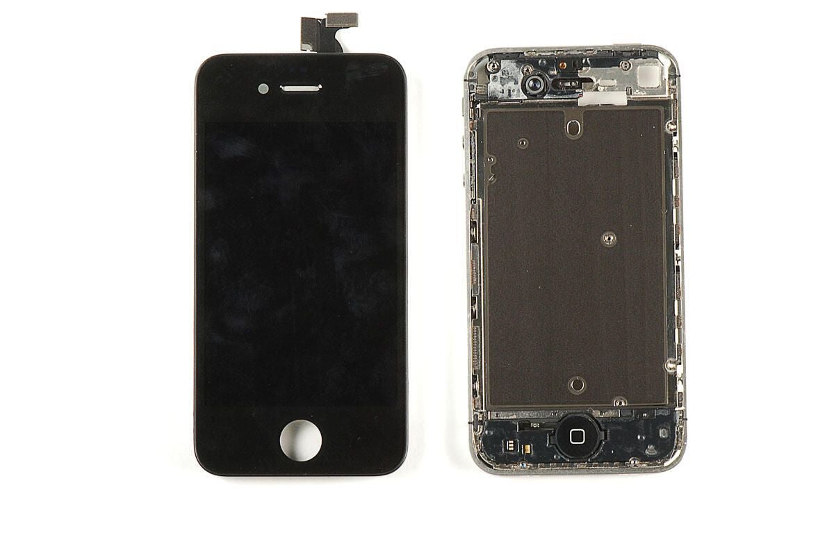
\n\tOnce the external case screws are removed, you can slide the back cover up and lift it away from the case.
\n\t
\n\tPhoto by: Bill Detwiler / TechRepublic
\n\tCaption by: Bill Detwiler
\n\tPhoto by: Bill Detwiler / TechRepublic
\n\tCaption by: Bill Detwiler
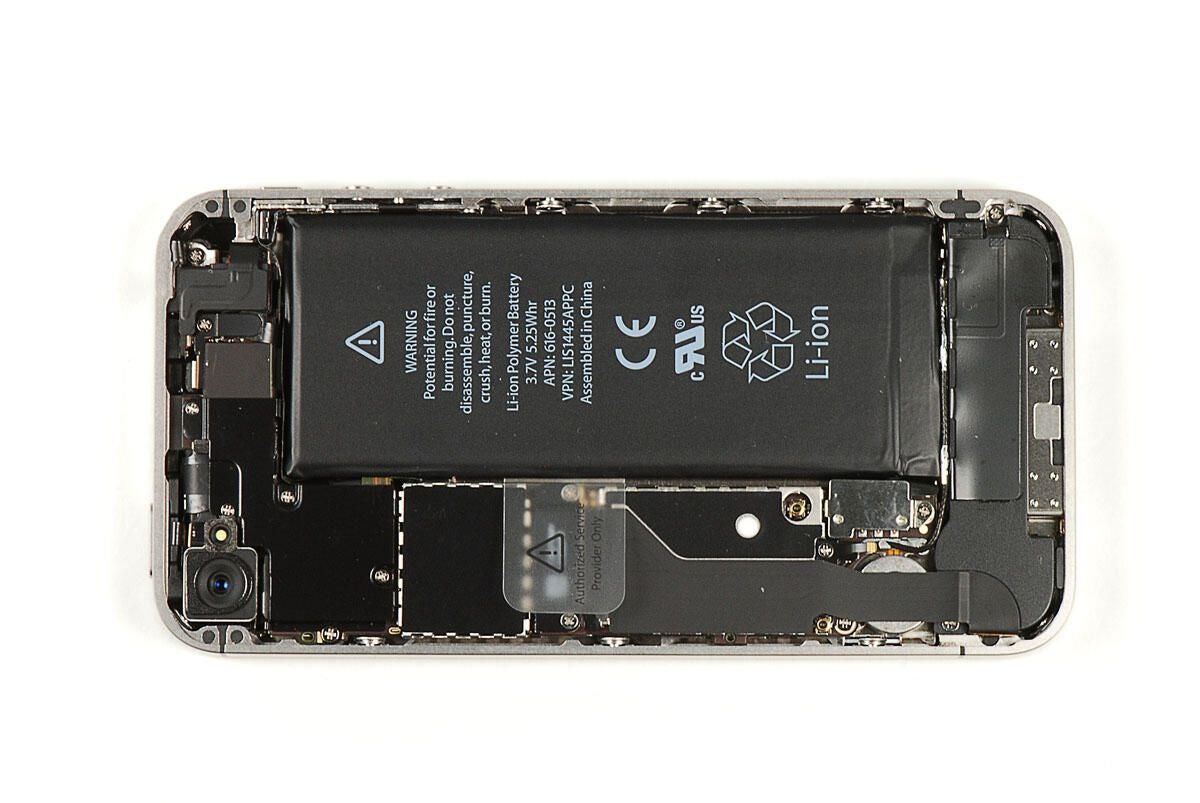
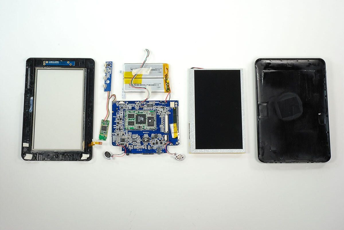
\n\tFor comparison, here’s a photo of the AT&T iPhone 4 from our, “Cracking Open the Apple iPhone 4,” gallery.
\n
\n\tPhoto by: Bill Detwiler / TechRepublic
\n\tCaption by: Bill Detwiler
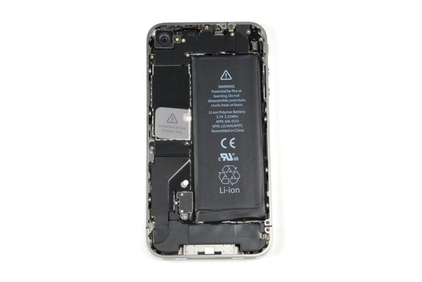
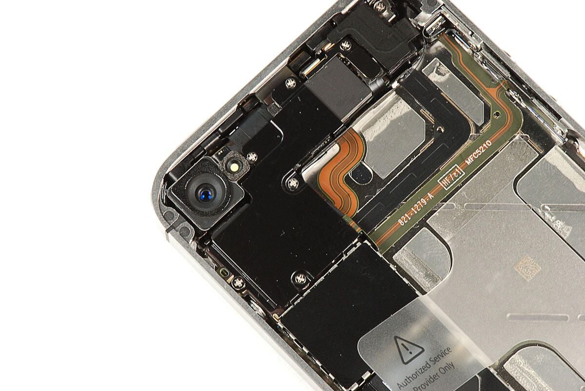
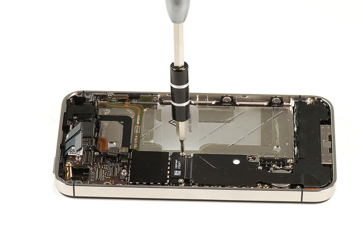
\n\tAt the top of the Verizon iPhone 4, there is a black metal shield covering part of the main PCB and several connectors. Five screws hold the shield in place. As the next phone shows, there’s a similar shield on the AT&T version of the iPhone 4, but it has a different shape.
\n\t
\n\tPhoto by: Bill Detwiler / TechRepublic
\n\tCaption by: Bill Detwiler
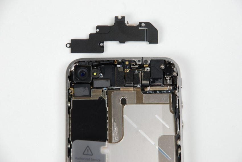
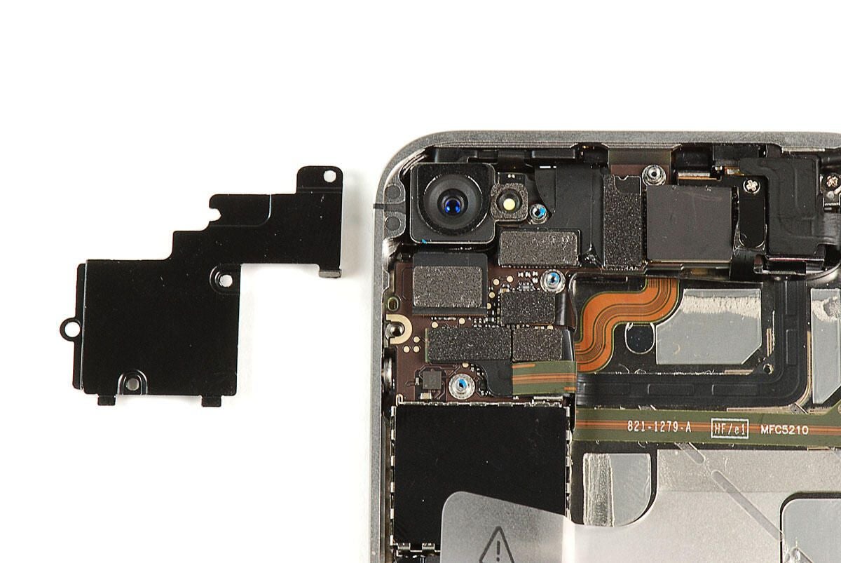
\n\tHere’s the upper-PCB shield on the AT&T iPhone 4. Notice that it has a very different shape than the shield on the Verizon version.
\n
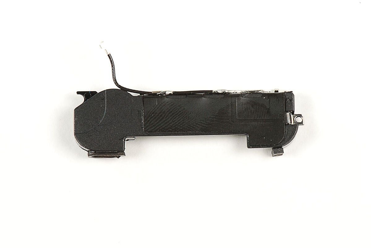
\n\tPhoto by: Bill Detwiler / TechRepublic
\n\tCaption by: Bill Detwiler
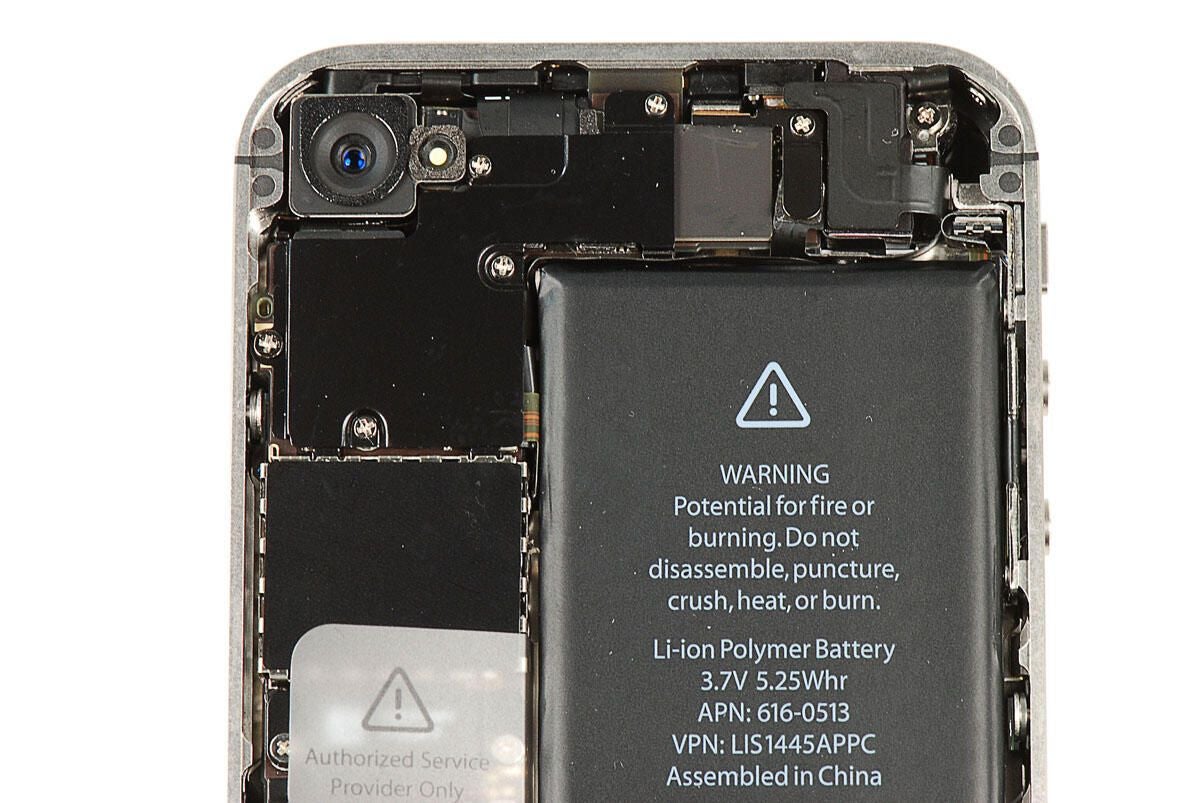
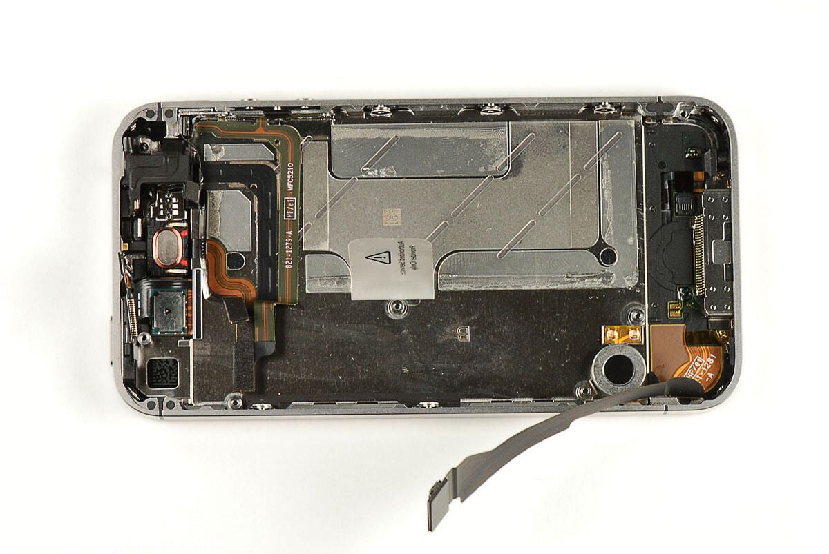
\n\tAt the bottom of the iPhone 4 are the speaker assembly, redesigned vibration motor, and the 30-pin connector.
\n\t
\n\tPhoto by: Bill Detwiler / TechRepublic
\n\tCaption by: Bill Detwiler
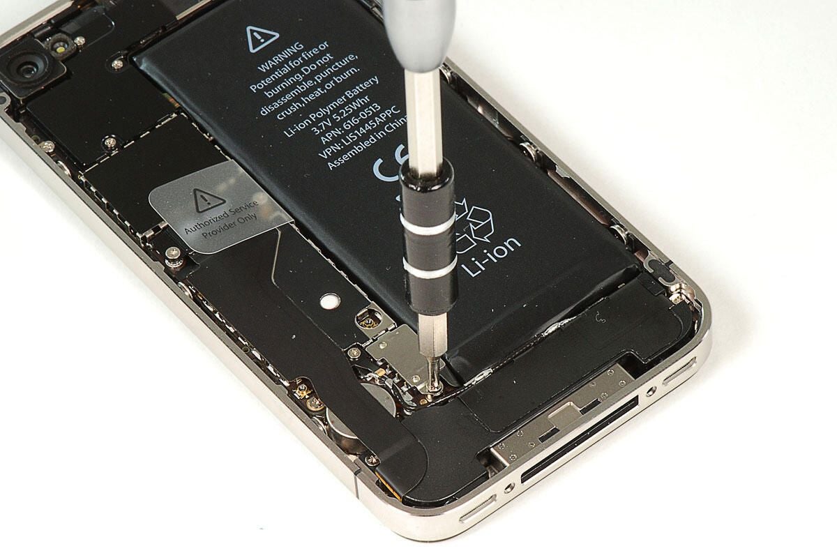
\n\tThe first step in dissecting the Verison iPhone 4 is removing the battery. The battery connector is held in place with a single Phillips #00 screw.
\n\t
\n\tPhoto by: Bill Detwiler / TechRepublic
\n\tCaption by: Bill Detwiler
\n\tWith the battery disconnected, you can lift it away from the Verizon iPhone 4’s metal frame. A small bit of adhesive holds the battery to the frame, but you should be able to pull the battery away without damaging it or the frame.
\n\t
\n\tPhoto by: Bill Detwiler / TechRepublic
\n\tCaption by: Bill Detwiler
\n\tWith the battery removed, we’ll turn our attention to the metal shield that covers the top of the main PCB.
\n\t
\n\tPhoto by: Bill Detwiler / TechRepublic
\n\tCaption by: Bill Detwiler
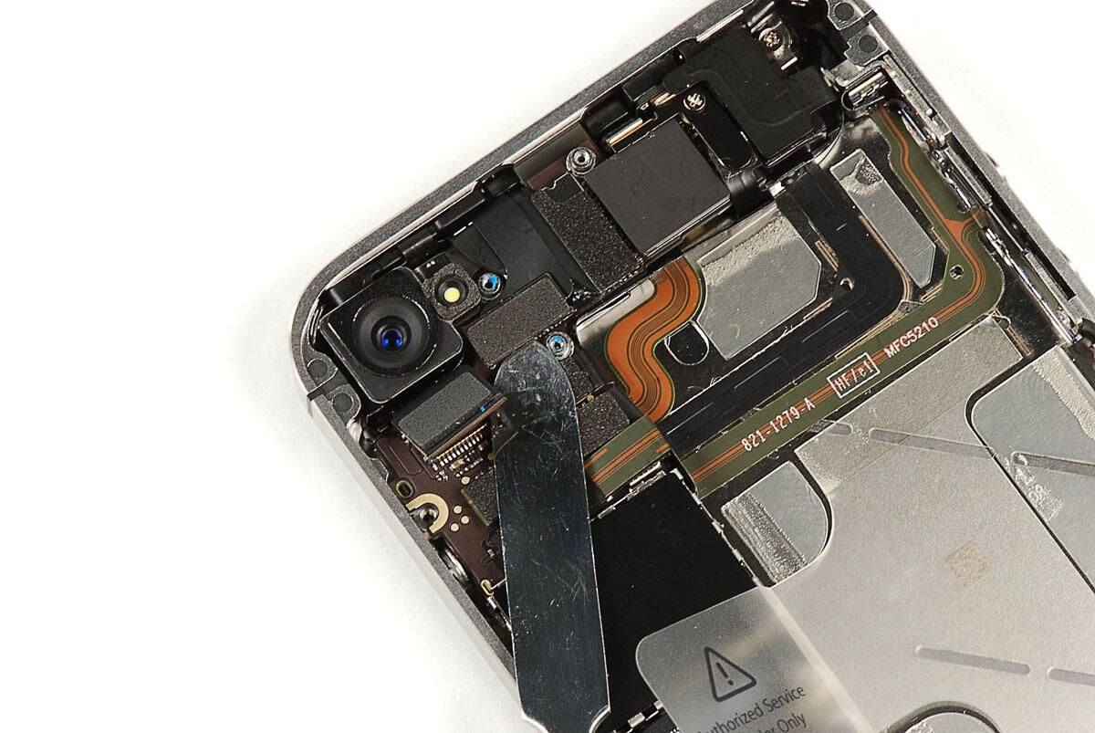
\n\tAs on the AT&T iPhone 4, the metal shield on the main PCB covers several connectors.
\n\t
\n\tPhoto by: Bill Detwiler / TechRepublic
\n\tCaption by: Bill Detwiler
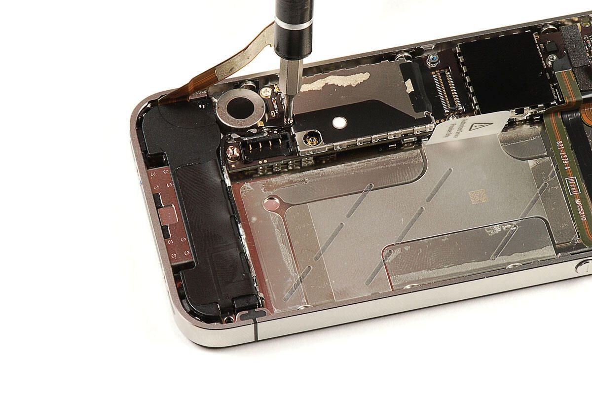
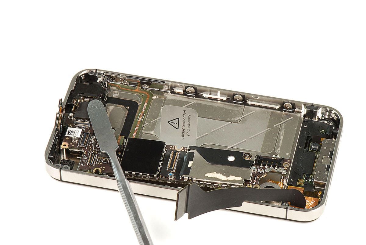
\n\tUsing a thin metal or plastic blade, you can disconnect the connectors.
\n\t
\n\tPhoto by: Bill Detwiler / TechRepublic
\n\tCaption by: Bill Detwiler
\n\tPhoto by: Bill Detwiler / TechRepublic
\n\tCaption by: Bill Detwiler
\n\tPhoto by: Bill Detwiler / TechRepublic
\n\tCaption by: Bill Detwiler
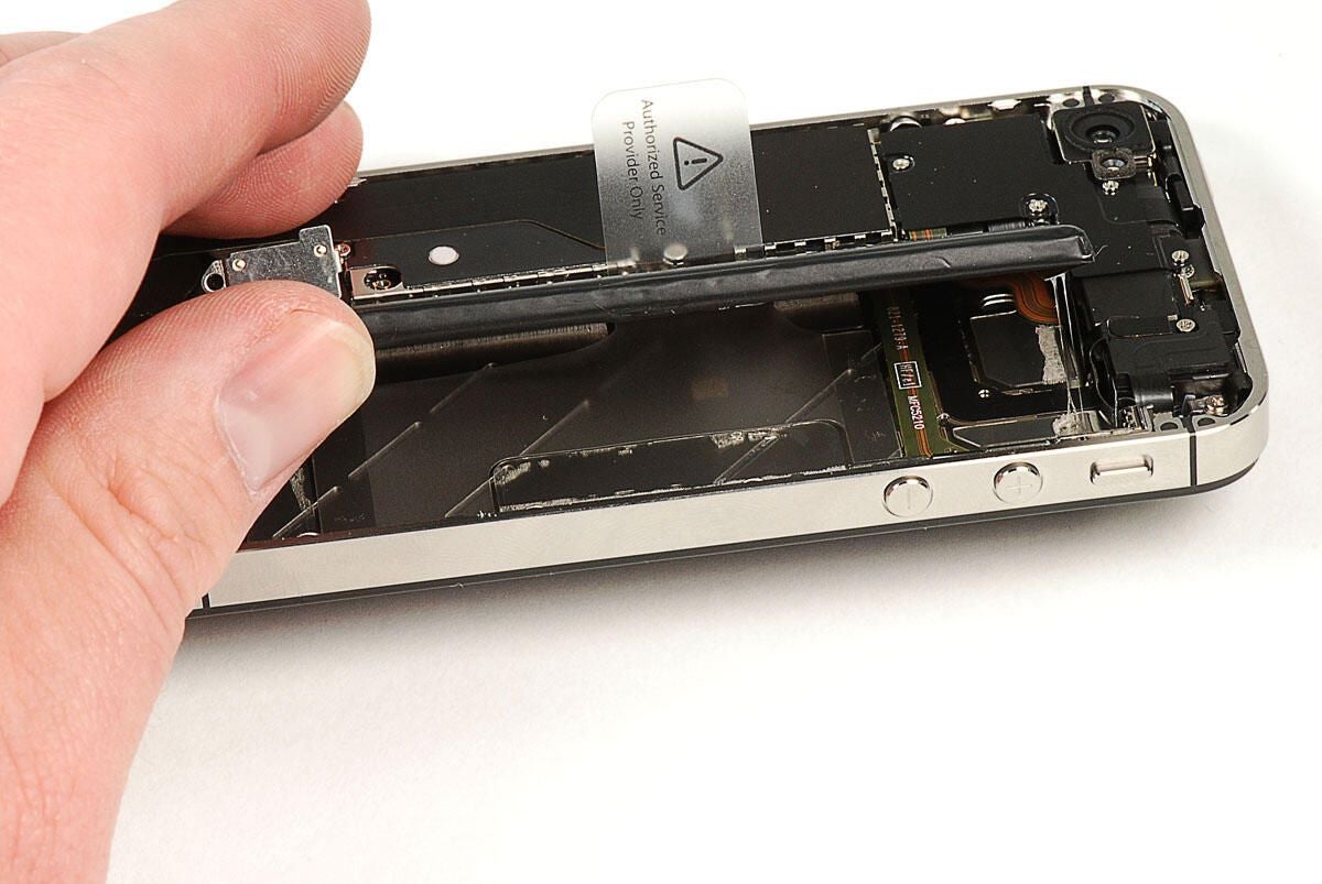
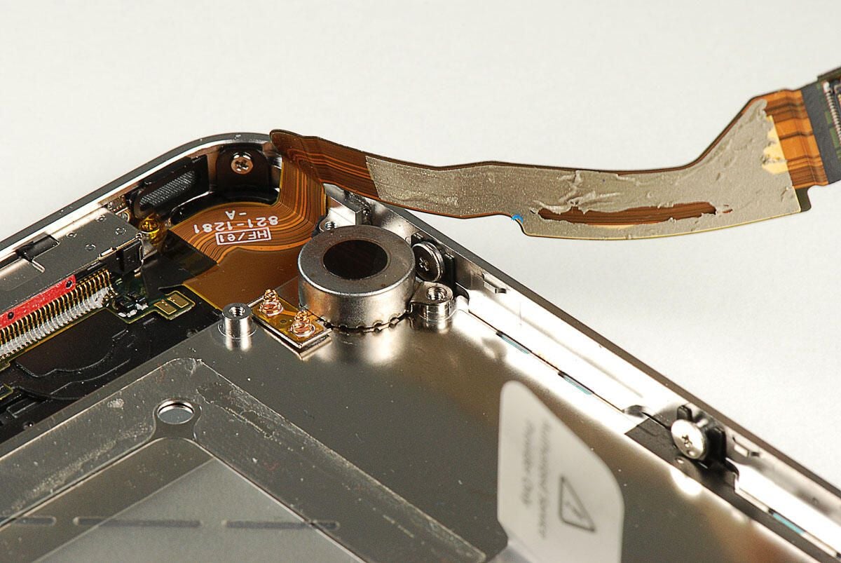
\n\tA black metal cover is mounted over the connector for a large ribbon cable that runs along the main PCB. Two screws hold the cover in place. We’ll need to remove both.
\n\t
\n\tPhoto by: Bill Detwiler / TechRepublic
\n\tCaption by: Bill Detwiler
\n\tPhoto by: Bill Detwiler / TechRepublic
\n\tCaption by: Bill Detwiler
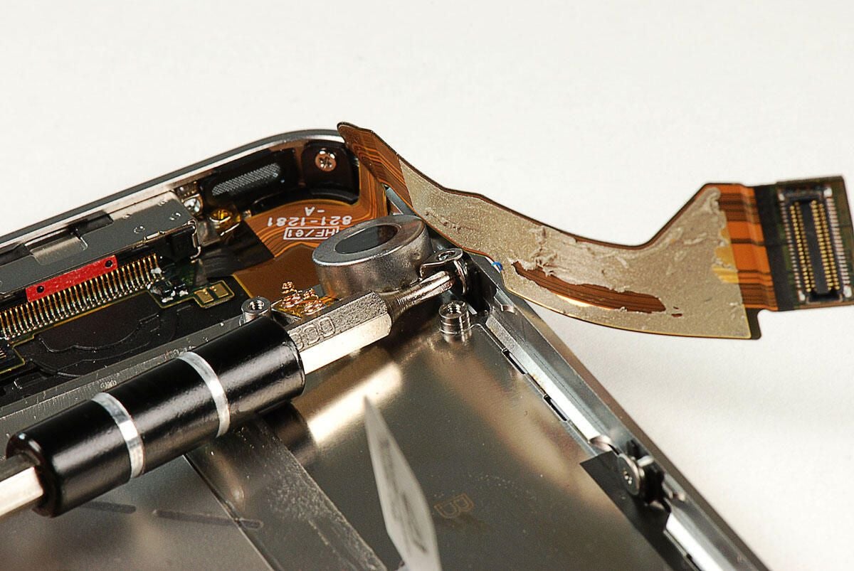
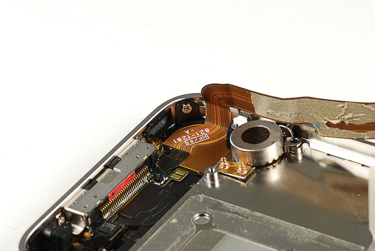
\n\tOnce the cover is removed, you can pop loose the connector.
\n\t
\n\tPhoto by: Bill Detwiler / TechRepublic
\n\tCaption by: Bill Detwiler
\n\tThe ribbon cable is attached to one of the main PCB’s metal shields with a small bit of adhesive.
\n\t
\n\tPhoto by: Bill Detwiler / TechRepublic
\n\tCaption by: Bill Detwiler
\n\tNext, we’ll remove the Phillips #00 screw that holds the speaker assembly to the frame.
\n\t
\n\tPhoto by: Bill Detwiler / TechRepublic
\n\tCaption by: Bill Detwiler
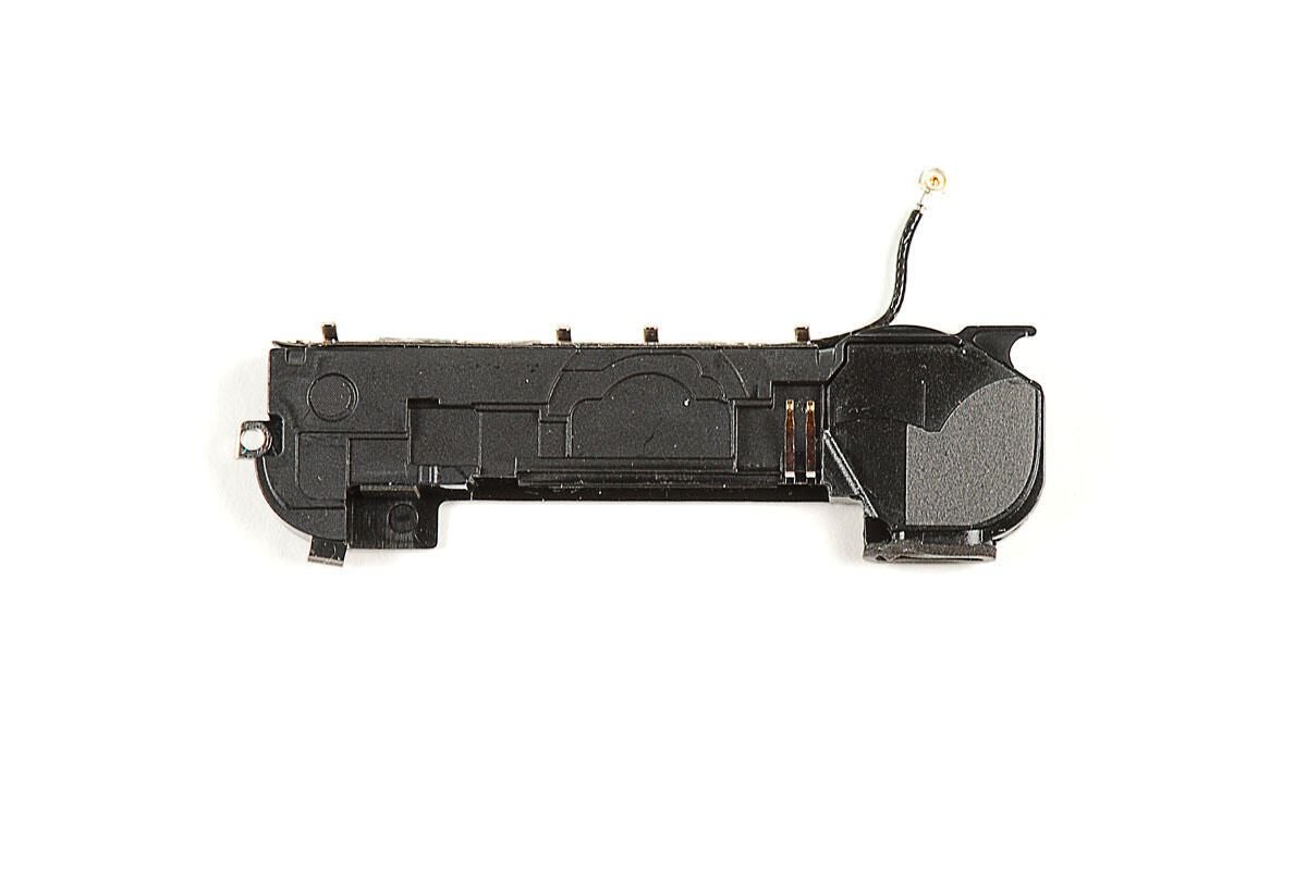
\n\tBefore we can remove the speaker assembly, we need to disconnect the Wi-Fi antenna cable that is attached to it. To disconnect the antenna from the main PCB, you’ll need to remove a thin metal piece, which acts as a ground when the back cover is in place. The metal ground is held in place with a single Phillips #00 screw.
\n\t
\n\tPhoto by: Bill Detwiler / TechRepublic
\n\tCaption by: Bill Detwiler
\n\tWith the metal ground removed, you can disconnect the Wi-Fi antenna wire from the main PCB.
\n\t
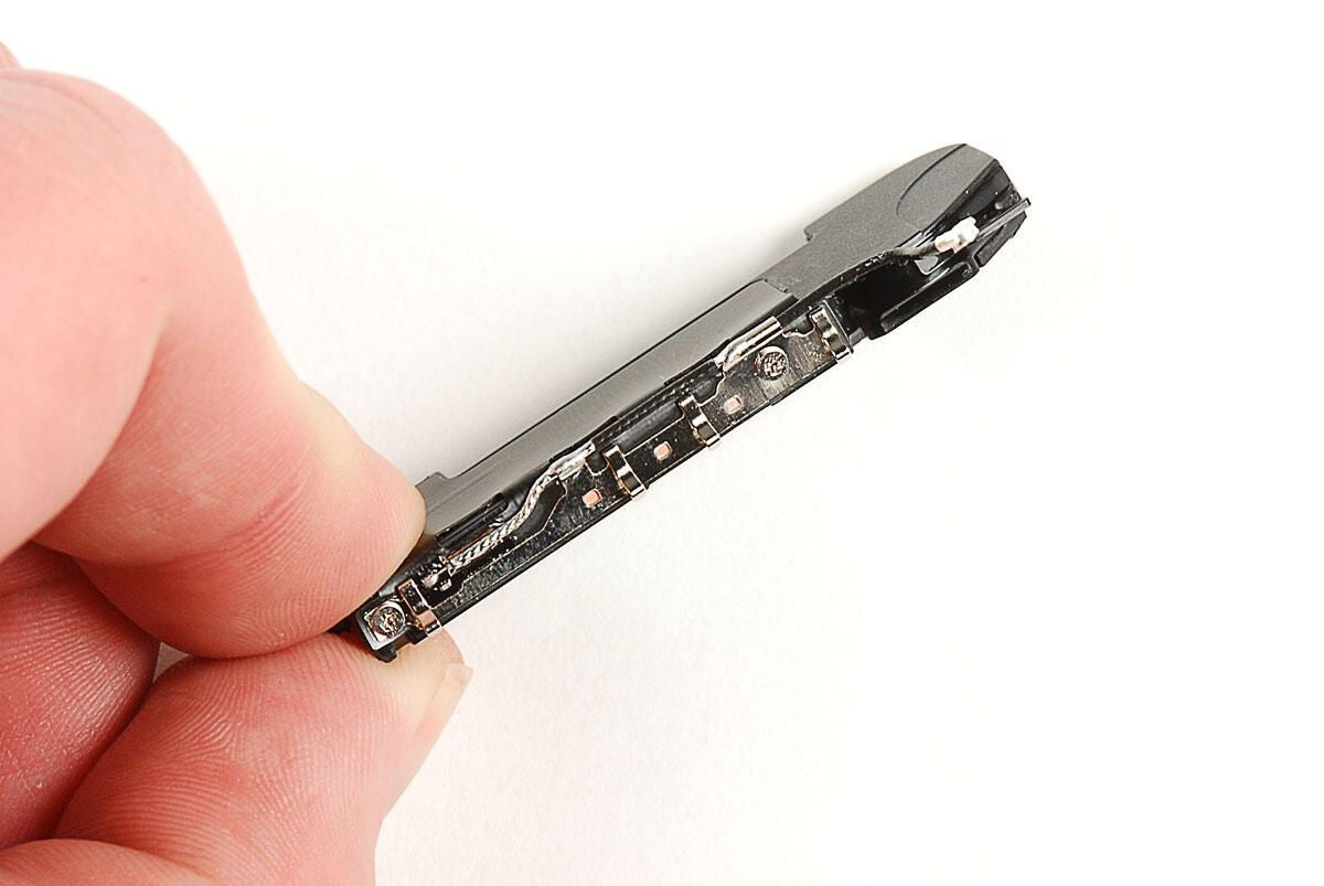
\n\tPhoto by: Bill Detwiler / TechRepublic
\n\tCaption by: Bill Detwiler
\n\tPhoto by: Bill Detwiler / TechRepublic
\n\tCaption by: Bill Detwiler
\n\tPhoto by: Bill Detwiler / TechRepublic
\n\tCaption by: Bill Detwiler
\n\tPhoto by: Bill Detwiler / TechRepublic
\n\tCaption by: Bill Detwiler
\n\tWith the speaker assembly removed, we are ready to remove the Verizon iPhone 4’s main PCB.
\n\t
\n\tPhoto by: Bill Detwiler / TechRepublic
\n\tCaption by: Bill Detwiler
\n\tSeveral Phillips #00 screws hold the Verizon iPhone 4’s main PCB to the metal frame beneath.
\n\t
\n\tPhoto by: Bill Detwiler / TechRepublic
\n\tCaption by: Bill Detwiler
\n\tBefore we can remove the main PCB from the Verizon iPhone 4, we need to make sure all the connectors have been disconnected.
\n\t
\n\tPhoto by: Bill Detwiler / TechRepublic
\n\tCaption by: Bill Detwiler
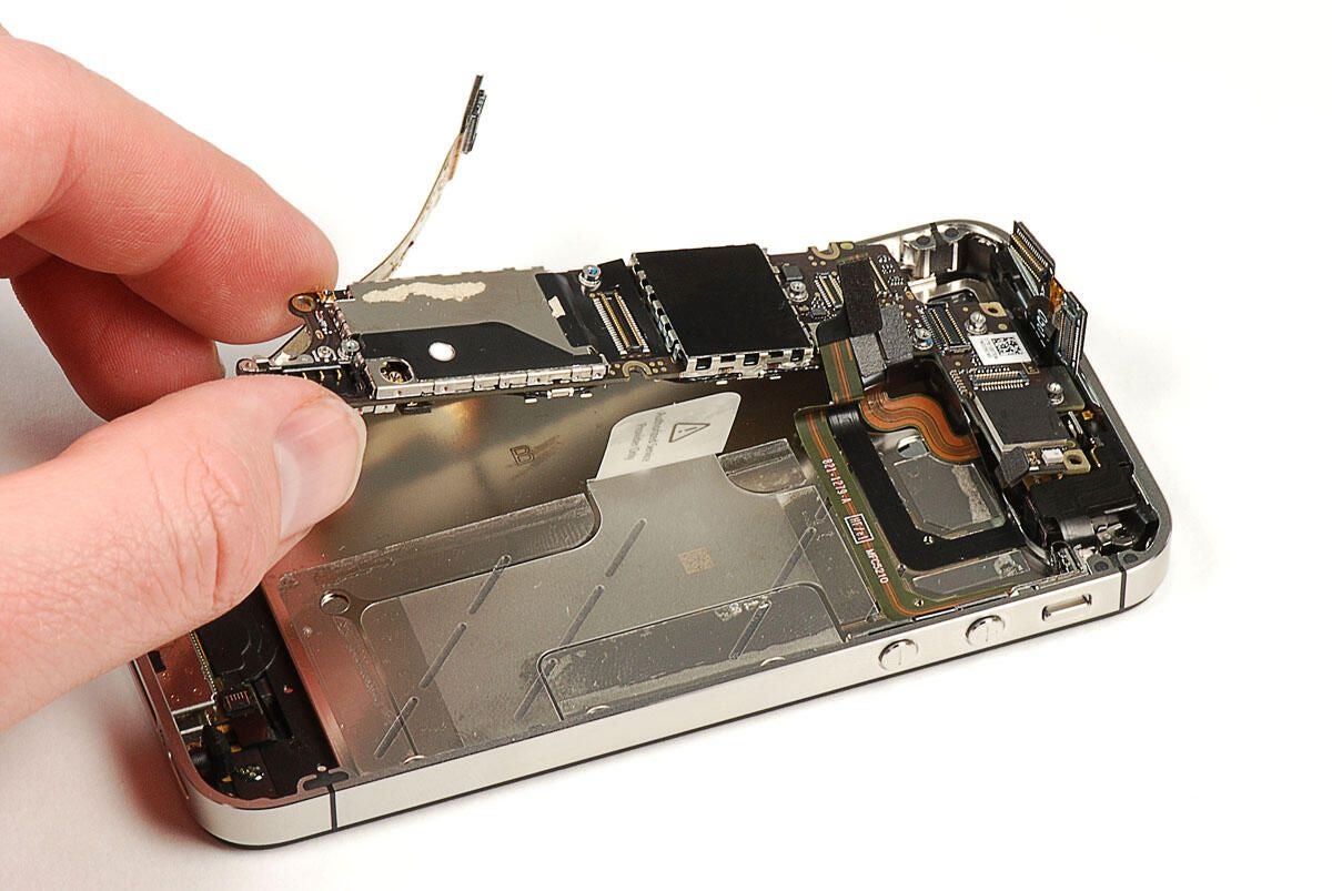
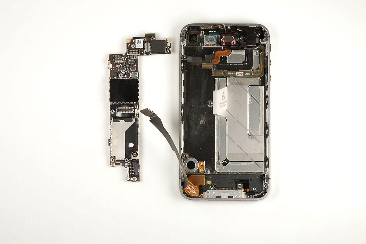
\n\tWith all the screws removed and connectors decoupled, you can left the main PCB away from the Verizon iPhone 4’s metal frame.
\n\t
\n\tPhoto by: Bill Detwiler / TechRepublic
\n\tCaption by: Bill Detwiler
\n\tPhoto by: Bill Detwiler / TechRepublic
\n\tCaption by: Bill Detwiler
\n\tTwo metal shields cover the chips on the top of the Verizon iPhone 4’s main PCB. We’ll need to remove them to see the chips underneath.
\n\t
\n\tPhoto by: Bill Detwiler / TechRepublic
\n\tCaption by: Bill Detwiler

\n\tSeveral metal shields also cover the chips on the underside of the Verizon iPhone 4’s main PCB.
\n\t
\n\tPhoto by: Bill Detwiler / TechRepublic
\n\tCaption by: Bill Detwiler
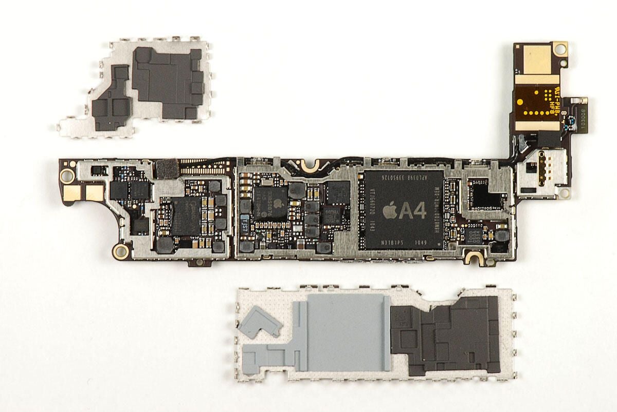
\n\tAfter removing the two metal shields from the main PCB, we can see several of the chips underneath. Including the large A4 processor.
\n\t
\n\tPhoto by: Bill Detwiler / TechRepublic
\n\tCaption by: Bill Detwiler
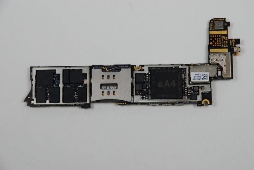
\n\tThis photo shows the top of the AT&T iPhone 4’s main PCB. Although the general shape and some of the chips are the same, it’s a completely different boarb from the Verizon iPhone.
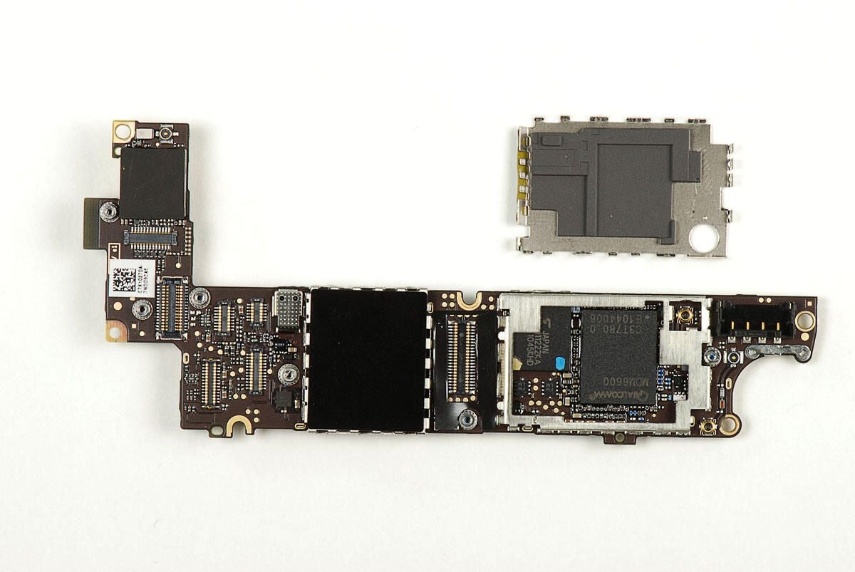
\n\tAfter removing the metal sheild from the underside of the main PCB, we can see a few of the chips beneath. One of the metal shields is soldered to the board, and I left it in place. I want to reassemble this phone in working condition.
\n\t
\n\tPhoto by: Bill Detwiler / TechRepublic
\n\tCaption by: Bill Detwiler
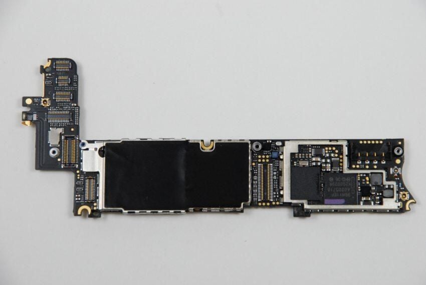
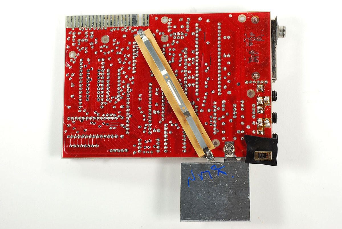
\n\tThis photo shows the back of the AT&T iPhone 4’s main PCB.
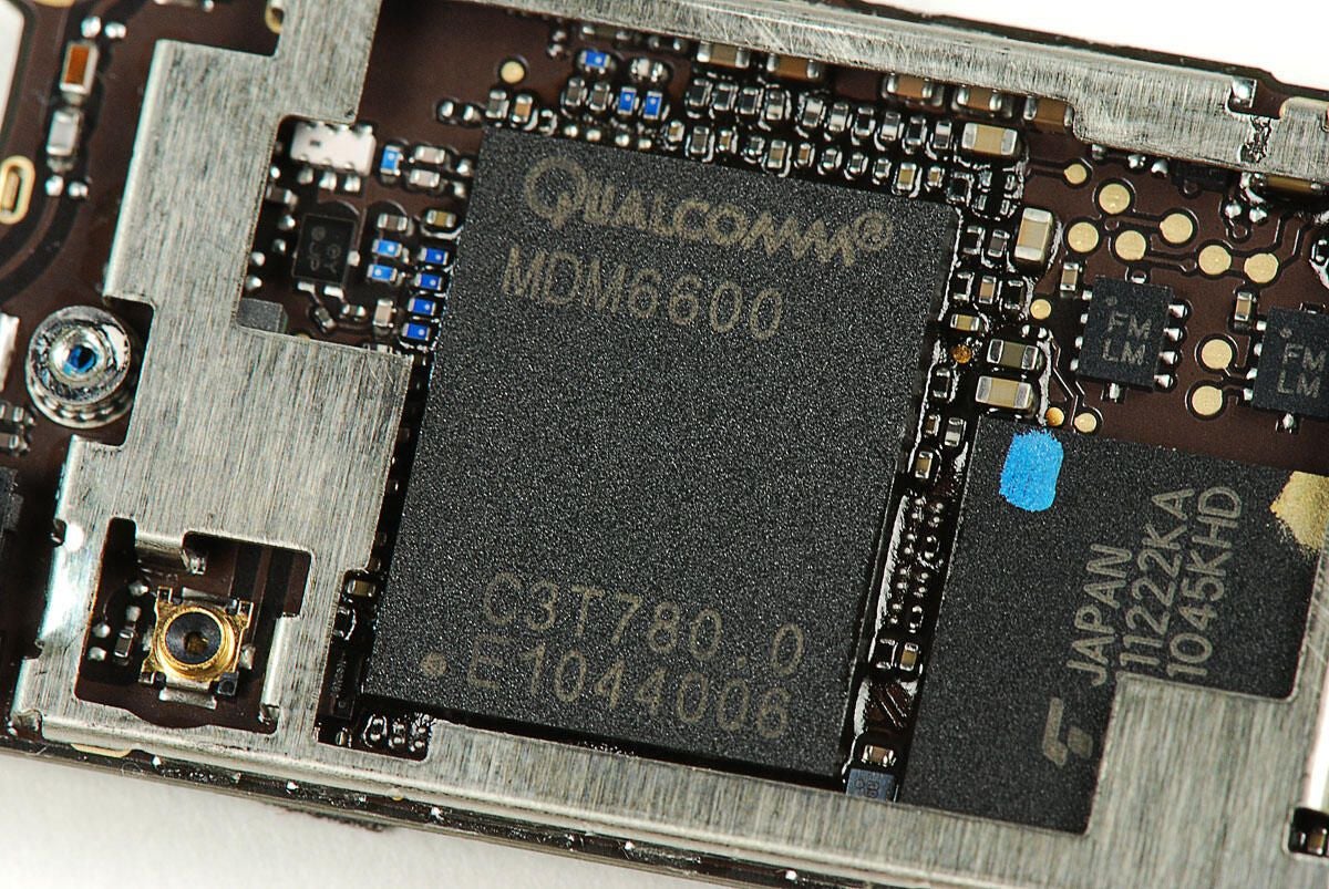
\n\tQualcomm MDM6600
\n\t
\n\tPhoto by: Bill Detwiler / TechRepublic
\n\tCaption by: Bill Detwiler
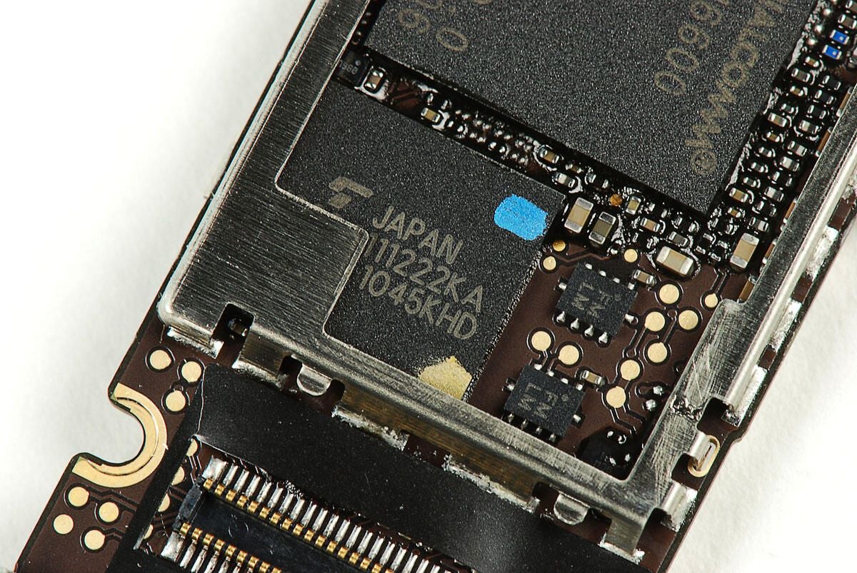
\n\tToshiba Y890A111222KA
\n\t
\n\tPhoto by: Bill Detwiler / TechRepublic
\n\tCaption by: Bill Detwiler
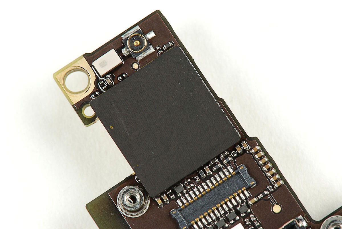
\n\tI’m unsure what’s beneath this black shield. I feared removing it would damage the components underneath.
\n
\n\tAccording the guys and gals over at iFixit, it’s likely that the chip under this shield provide the Verizon iPhone 4’s Wi-Fi and Bluetooth functionality.
\n\t
\n\tPhoto by: Bill Detwiler / TechRepublic
\n\tCaption by: Bill Detwiler
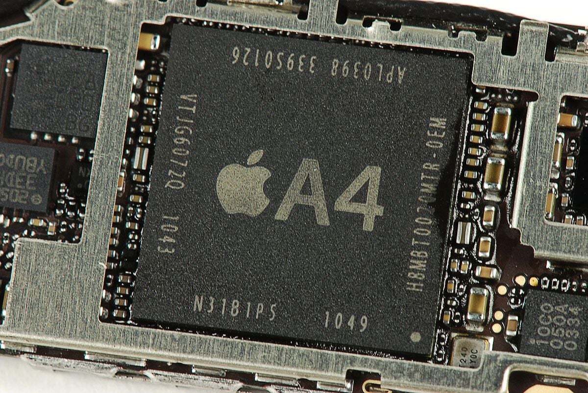
\n\tApple A4 Processor
\n\t
\n\tPhoto by: Bill Detwiler / TechRepublic
\n\tCaption by: Bill Detwiler
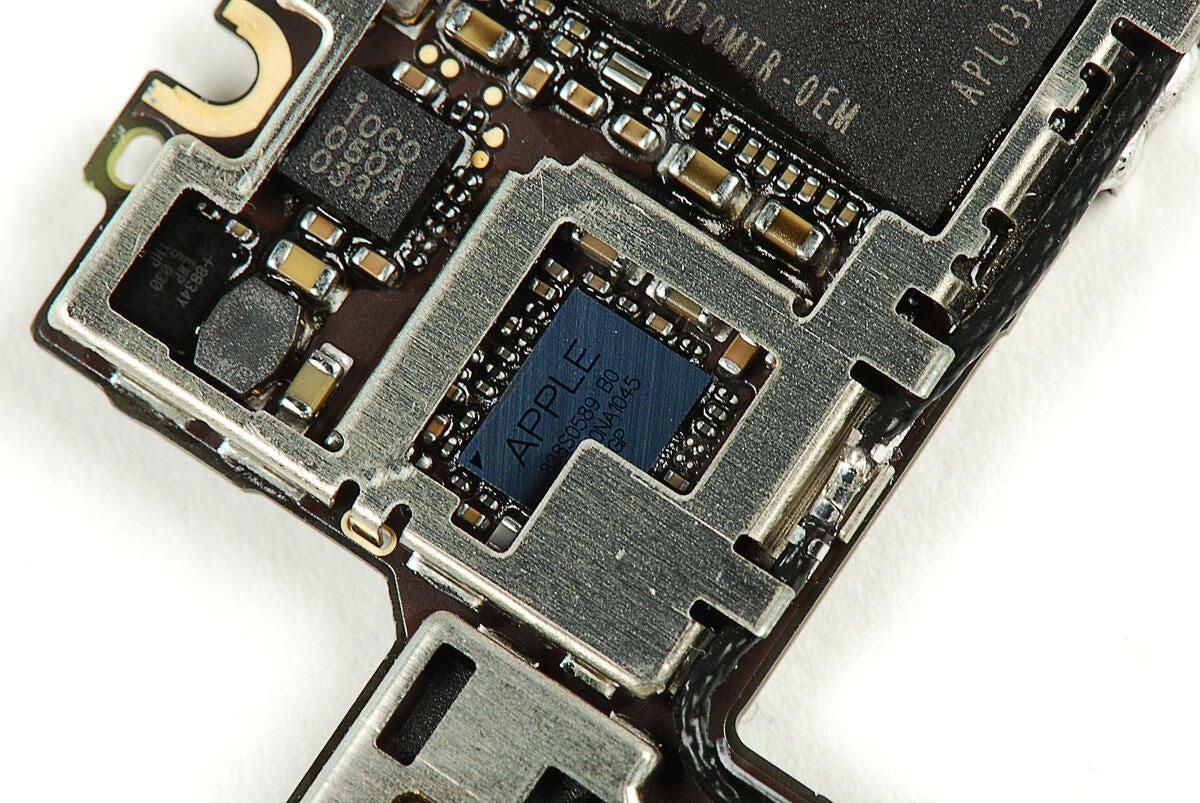
\n\tApple branded 338S0589 B0 chip
\n\t
\n\tPhoto by: Bill Detwiler / TechRepublic
\n\tCaption by: Bill Detwiler
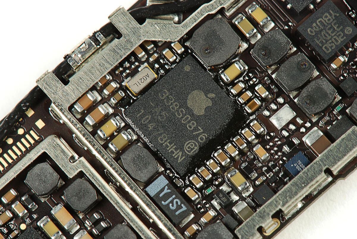
\n\tApple branded 338S0876-A5
\n\t
\n\tPhoto by: Bill Detwiler / TechRepublic
\n\tCaption by: Bill Detwiler

\n\tQualcomm PM8028
\n\t
\n\tPhoto by: Bill Detwiler / TechRepublic
\n\tCaption by: Bill Detwiler
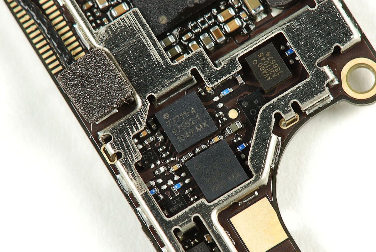
\n\tSkyworks (SKY77711-4 and SKY77710-4) Power amplifiers
\n\t
\n\tPhoto by: Bill Detwiler / TechRepublic
\n\tCaption by: Bill Detwiler

\n\tAvago A2F1045 136574
\n\t
\n\tPhoto by: Bill Detwiler / TechRepublic
\n\tCaption by: Bill Detwiler
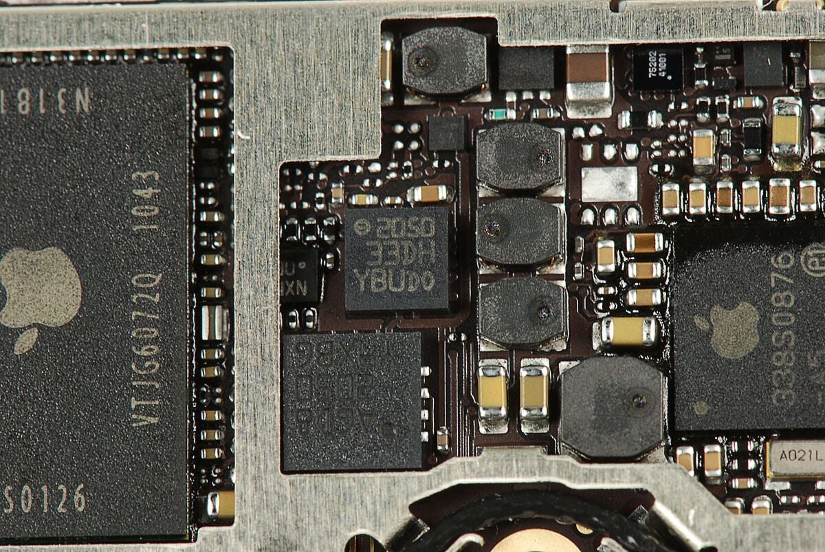
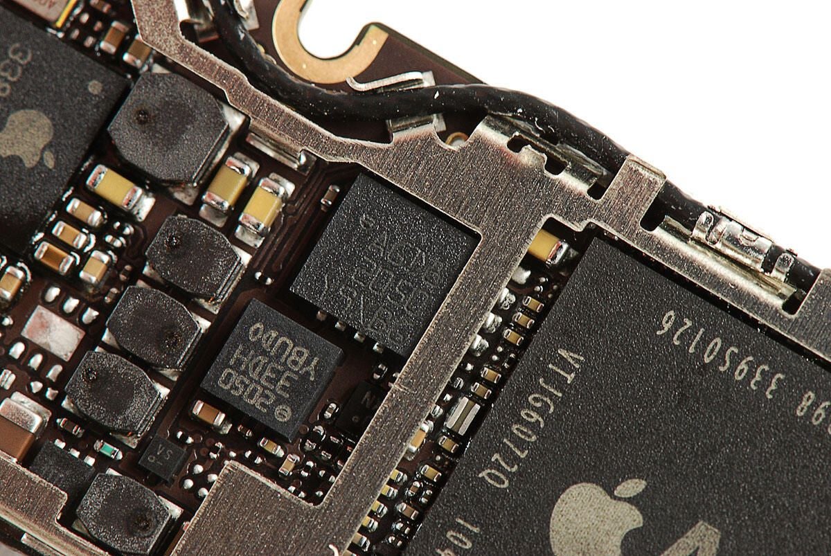
\n\tChip with markings 2050 33DH YBU DO
\n\t
\n\tPhoto by: Bill Detwiler / TechRepublic
\n\tCaption by: Bill Detwiler
\n\tChips with marking AGD8 2050 Y9XB6
\n\t
\n\tPhoto by: Bill Detwiler / TechRepublic
\n\tCaption by: Bill Detwiler
\n\t
\n\t
\n\tPhoto by: Bill Detwiler / TechRepublic
\n\tCaption by: Bill Detwiler
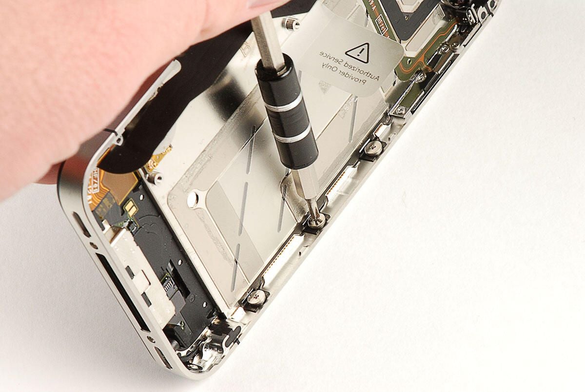
\n\tSeveral Phillips #00 screws along the side of the metal frame hold the mounting brackets for the display assembly in place. You just need to loosen, not remove, these screws.
\n\t
\n\tPhoto by: Bill Detwiler / TechRepublic
\n\tCaption by: Bill Detwiler
\n\tOne of the side screws for the display assembly is located behind the redesigned vibration motor. The motor is attached to the metal frame with very sticky adhesive. I decided not to completely remove the motor, but instead to gently push it to the side–just enough to reach the screw.
\n\t
\n\tPhoto by: Bill Detwiler / TechRepublic
\n\tCaption by: Bill Detwiler
\n\tI was able to move the vibration motor just enough to reach the screw behind it.
\n\t
\n\tPhoto by: Bill Detwiler / TechRepublic
\n\tCaption by: Bill Detwiler
\n\tThere’s one screw in each corner of the display assembly.
\n\t
\n\tPhoto by: Bill Detwiler / TechRepublic
\n\tCaption by: Bill Detwiler
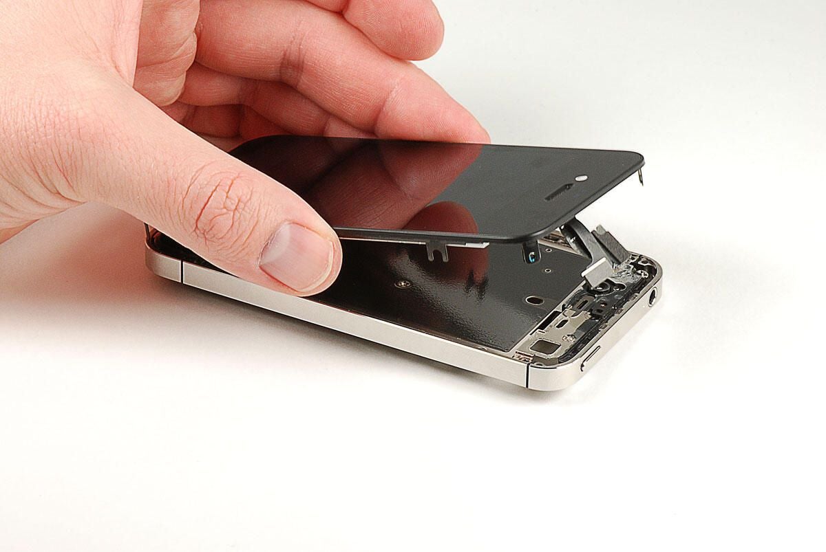
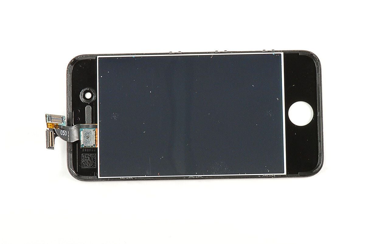
\n\tWith all the screws removed, you can lift the display assembly away from the metal frame. A small patch of adhesive located near the headphone jack will give you a bit of resistence, but isn’t too difficult to work through.
\n\t
\n\tPhoto by: Bill Detwiler / TechRepublic
\n\tCaption by: Bill Detwiler
\n\t
\n\t
\n\tPhoto by: Bill Detwiler / TechRepublic
\n\tCaption by: Bill Detwiler
\n\t
\n\t
\n\tPhoto by: Bill Detwiler / TechRepublic
\n\tCaption by: Bill Detwiler
\n\t
\n\t
\n\tPhoto by: Bill Detwiler / TechRepublic
\n\tCaption by: Bill Detwiler
Bill Detwiler is the Editor for Technical Content and Ecosystem at Celonis. He is the former Editor in Chief of TechRepublic and previous host of TechRepublic's Dynamic Developer podcast and Cracking Open, CNET and TechRepublic's popular online show. Previously, Bill was an IT manager in the social research and energy industries. He has bachelor's and master's degrees from the University of Louisville, where he has also lectured on computer crime and crime prevention.


