In my previous TechRepublic article I described how to rack and stack Cisco Unified Computing System (UCS) B-Series blade servers. In this article I’ll delve more into how to configure the UCS Manager (UCSM) software for initial use.
The UCSM can be intimidating, because there’s a ton of configurable features with the blades; I’ll concentrate on getting to know the UCSM. I’ll use the Cisco UCS Emulator to show the examples.
An overview of the UCSM
The Fault Summary (Figure A top left) reveals all of the faults within our entire UCS infrastructure. When you click any of the faults identified, you’ll be taken to the Faults tab under Admin to get more information.
Figure A
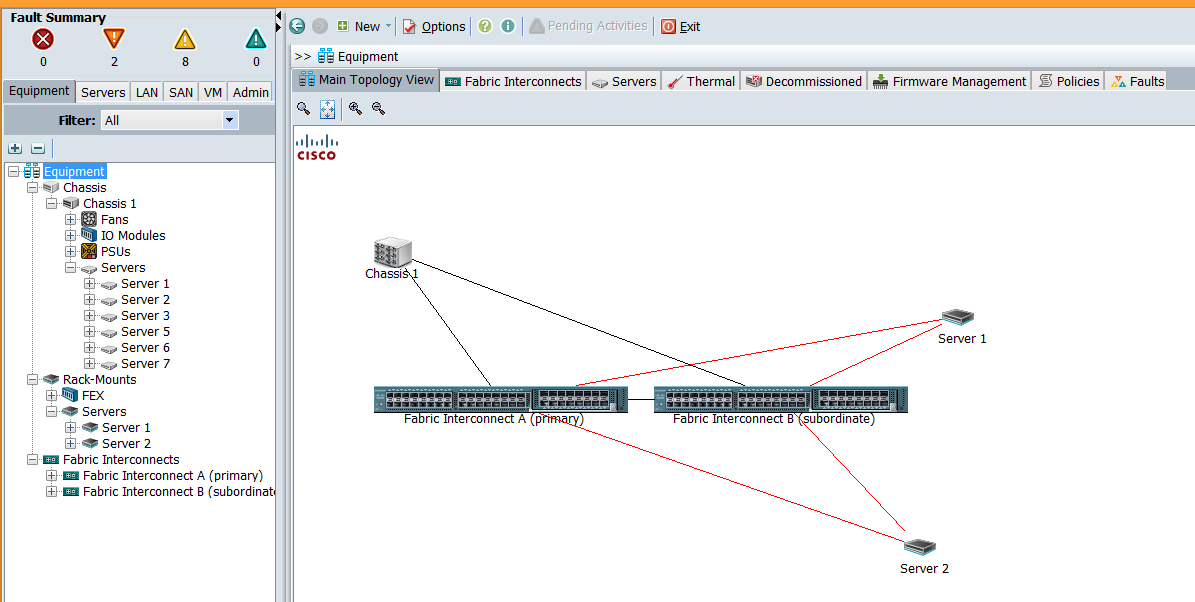
Below the Fault Summary you see six tabs: Equipment, Servers, LAN, SAN, VM, and Admin. Here’s a brief description of each tab.
Equipment tab
The Equipment tab (Figure A) is where you can see all of the hardware associated with your UCS infrastructure. When you highlight Equipment, you get an overview, but you can also click the various components such as Chassis, Server, Fabric Interconnects (FIs), and even Rack-Mount servers if you have UCS C-series servers connected to your FIs.
As an example let’s highlight one of our servers. We see several tabs in the main pane of the window (Figure B).
Figure B
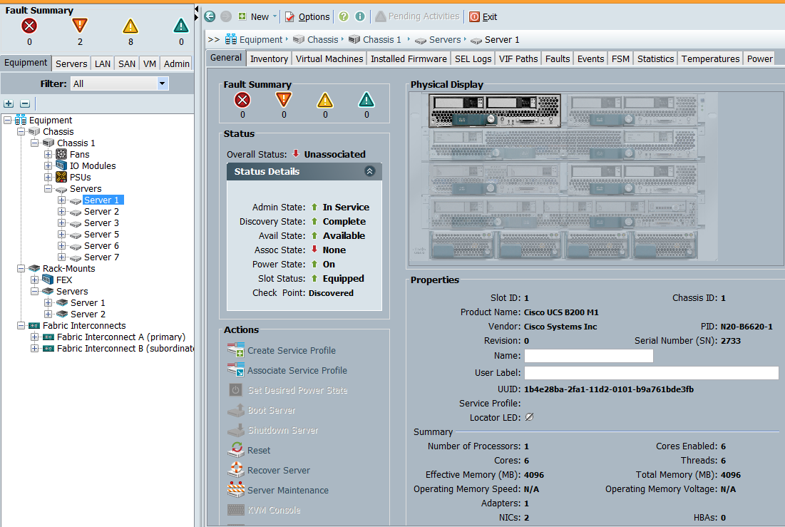
In the General tab we get an overview of the specific component we highlighted, which in this case is Server1. We see a Fault Summary for this specific server, as well as the Overall Status. This shows the status as Unassociated, which means there’s no service profile associated with this server. The Status Details shows us that everything is in an up state except for the Assoc. State as shown in the Overall Status.
In the Actions tab we can do several things, including Associate a Service Profile and Power On, Power Off, or Reset the server; this means we can control the state of the server remotely, as long as we have network connectivity to the UCSM. We can also open a KVM console from this screen; this allows us to see what would be on a monitor if we were plugged in physically to the server. This KVM will also allow us to mount .ISO files if we want to install an operating system remotely, for example.
On the right side we see a picture of the front of the UCS — everything is grayed out except for the component we’re looking at. We can double-click the components in this picture to get information on different components. Below this picture we see Properties of our Server1. We can see we’re working with a B200 M1, as well as the UUID, how many processors, cores, RAM, etc.; the rest of the tabs are somewhat self-explanatory. With Inventory we can dive into the various components within the server. You can click the FSM (Finite State Machine) tab after kicking off a task to see the status of the task completion.
Servers tab
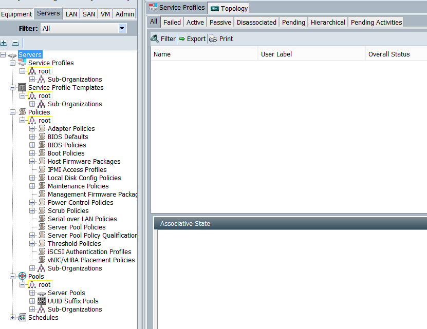
The Servers tab (Figure C) has more to do with what some refer to as stateless computing; this is where you create things like Service Profile Templates and Service Profiles, which then get associated with a physical server. You can almost think of it as an abstracted layer whereby you can assign virtual NICs (vNICs), virtual HBAs, boot orders, etc. to a profile that will be assigned to a physical server.
Figure C
LAN tab
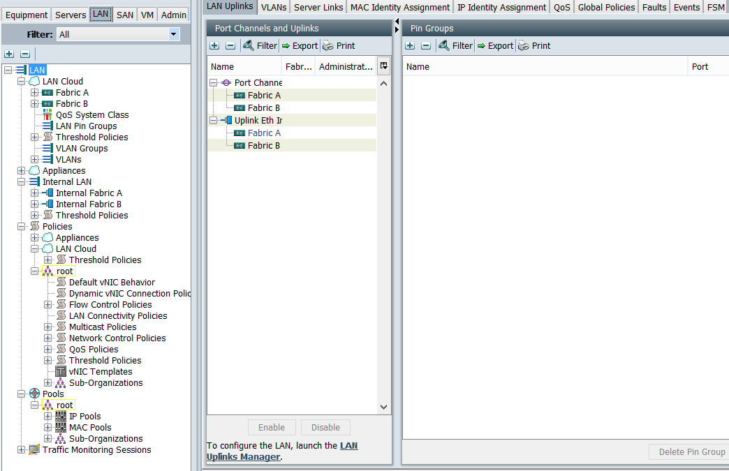
The LAN tab (Figure D) is anything network related. We’ll create vNIC templates here that will later be assigned to a Service Profile. These vNICs are virtual NICs that we want to see on each server.
Since the servers don’t have physical NICs, as they connect to the Chassis (which gets its bandwidth via the connections from the FEX to the FI), we have to create vNICs. Under this tab, we’ll also configure VLANs, create Port Channels under the LAN cloud heading, and even configure different settings for Fabric A and Fabric B if we want. We’ll get into more of this in future articles about configuration.
Figure D
SAN tab
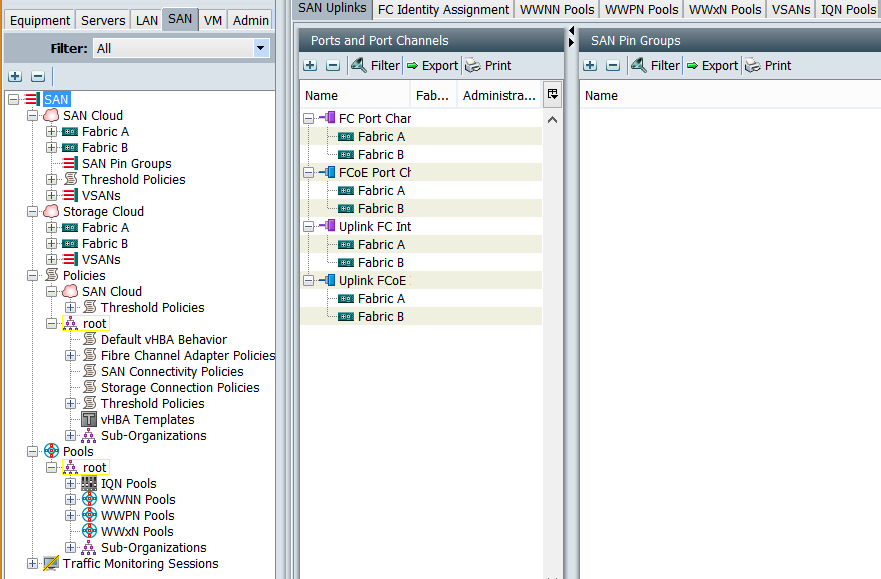
The SAN tab (Figure E) is very similar to the LAN tab except it has to do with everything storage. In this case we set up vHBAs, though, to connect to storage. Like the vNICs, we’ll see these HBAs through our operating systems and be able to connect to the storage using Fibre Channel. We also set up WWNN and WWPN pools if we’re using Fibre Channel, or IQN pools if we’re using iSCSI to connect physically to the storage. Once we have all these configured and we have an operating system loaded on our servers such as VMware ESXi, we can register our hosts on the storage arrays and start setting up Datastores (shared storage).
Figure E
VM tab
The VM tab requires an Enterprise Plus License for VMware vSphere, and is only meant to be used if you’re running VM-FEX.
Admin tab
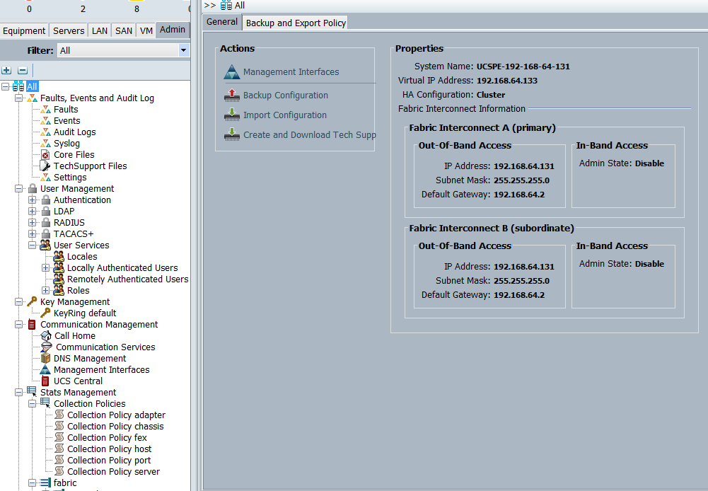
The Admin tab (Figure F) is where you can see Faults, set up users and authentication, configure Call Home, set up UCS Central, configure NTP, and a ton of other administrative tasks usually associated with server provisioning.
Figure F
Stay tuned
In future articles, I’ll get into the configuration aspects of using UCSM, which will enable us to start using the servers.
If you have questions or comments about this topic, please post them in the discussion.