\n\tWant a tablet, but don’t want to spend $500 for an Apple iPad or Samsung Galaxy Tab? Then you might be tempted to purchase one of the many $100 Android tablets that are floating around the Web. These low-priced devices offer features similar to their higher-end cousins (touchscreen, built-in camera, and Wi-Fi). But, what’s really inside a $100 tablet? We wanted to find out. So, we bought one from a site called FocalPrice.com — the LY-706 MID Tablet Pad Netbook. Follow along as we take a peak at the hardware inside this low-cost tablet.
\n\t
\n\tPhoto by: Bill Detwiler / TechRepublic
\n\tCaption by: Bill Detwiler
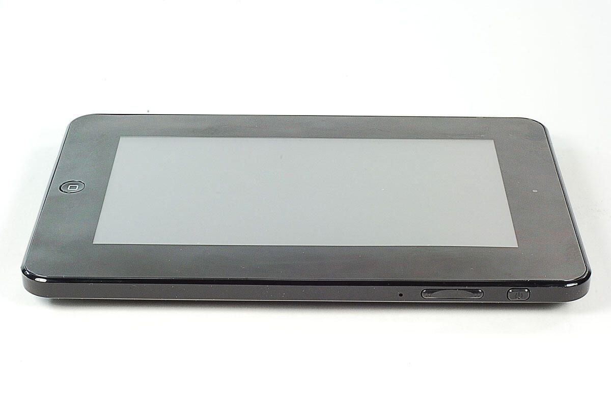
\n\tAs of this writing, FocalPrice lists the LY-706 tablet at $97.99 (US) with free shipping. The device has a 7-inch TFT-LCD (800×480 resolution) with resistive touchscreen, built-in speakers and microphone, and a 1.3MB front-facing camera. Inside the LY-706, you’ll find a VIA MW8505 CPU, 2GB of NAND flash storage, and 256MB system memory. It also supports Wi-Fi.
\n
\n\tThe LY-706 comes with Android 1.6 installed.
\n\t
\n\tPhoto by: Bill Detwiler / TechRepublic
\n\tCaption by: Bill Detwiler
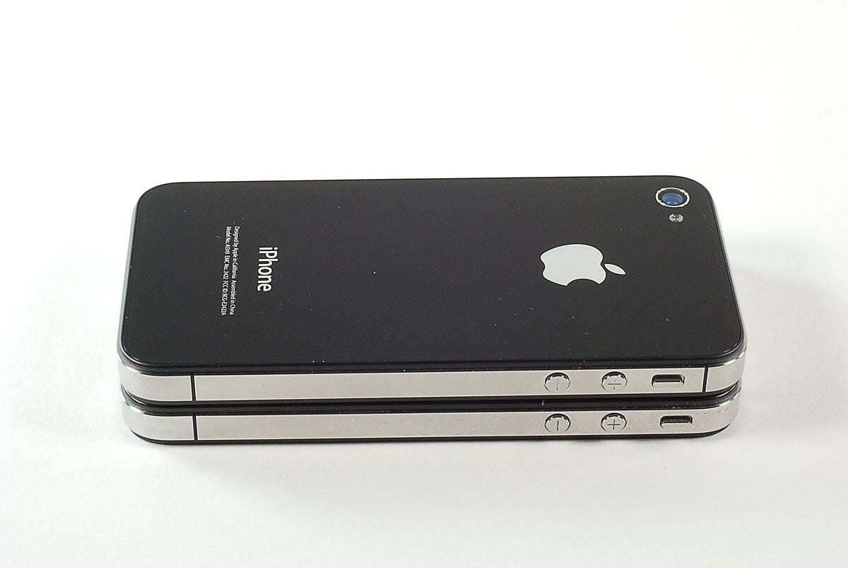
\n\tThe LY-706 is a bit thincker than the iPad, but still feels comfortable in the hand.
\n
\n\tPhoto by: Bill Detwiler / TechRepublic
\n\tCaption by: Bill Detwiler
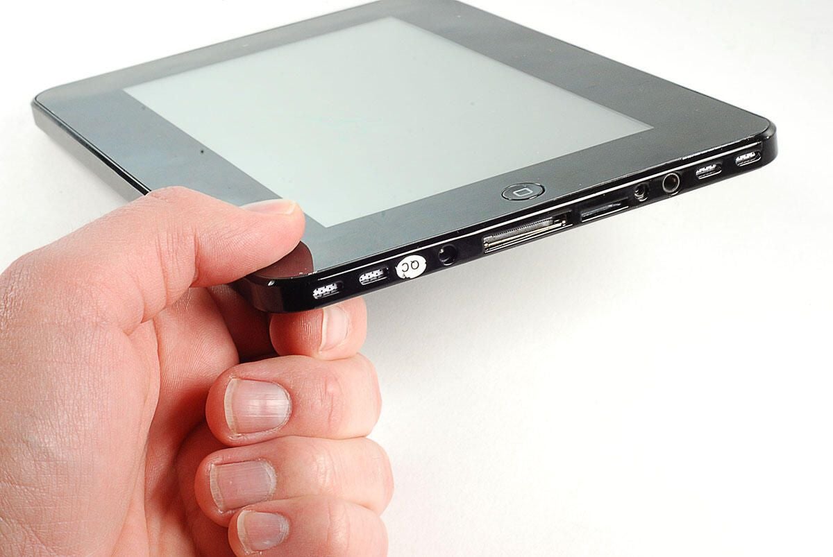
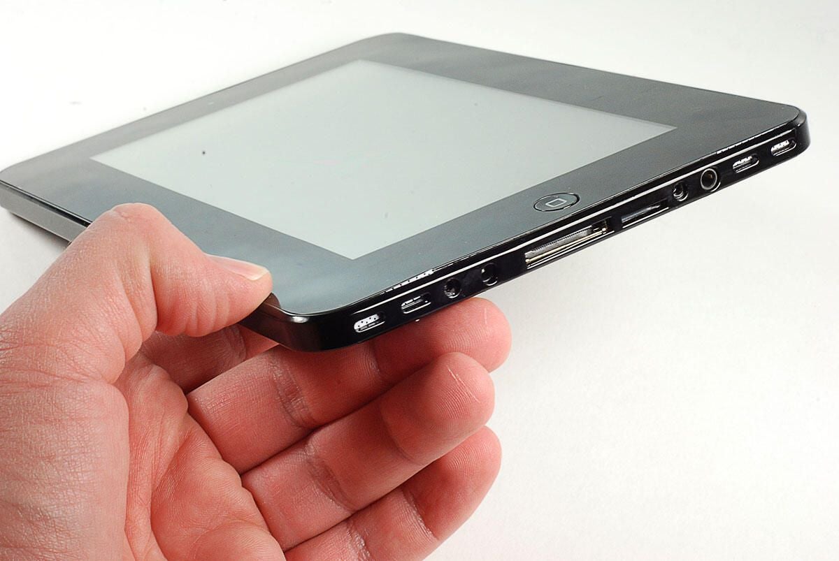
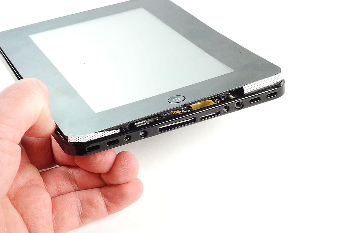
\n\tAlong the bottom of the LY-706 are the speaker grills, 3.5mm headphone jack, 30-pin connector, microSD card slot, and power connector.
\n
\n\tPhoto by: Bill Detwiler / TechRepublic
\n\tCaption by: Bill Detwiler
\n\tAlong the right side of the LY-706 are the power button, volume buttons, and hole that doubles as the mic and reset button.
\n
\n\tPhoto by: Bill Detwiler / TechRepublic
\n\tCaption by: Bill Detwiler
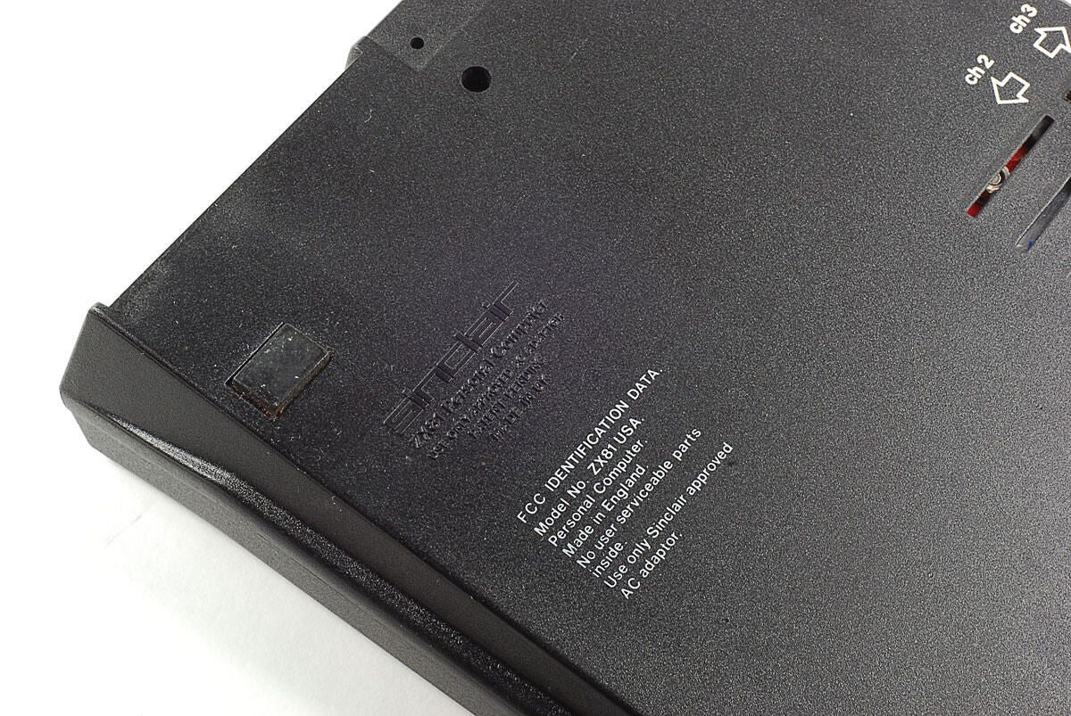
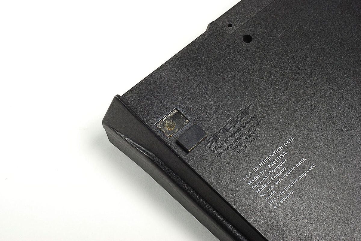
\n\tOne of the strange things about the LY-706 tablet is the lack of identifying marks. Other than model number and input power voltage, there are no other markings that identify the device. And despite looking, I was never able to determine who actually assembled the LY-706.
\n
\n\tPhoto by: Bill Detwiler / TechRepublic
\n\tCaption by: Bill Detwiler
\n\tThe second external case screw is hidden behind a small white sticker with the markings QC.
\n
\n\tPhoto by: Bill Detwiler / TechRepublic
\n\tCaption by: Bill Detwiler
\n\tOnce I removed the external screws, the display assembly immediately popped up from the back cover. This was one of several occurances that illustrated the LY-706’s poor assembly.
\n
\n\tPhoto by: Bill Detwiler / TechRepublic
\n\tCaption by: Bill Detwiler
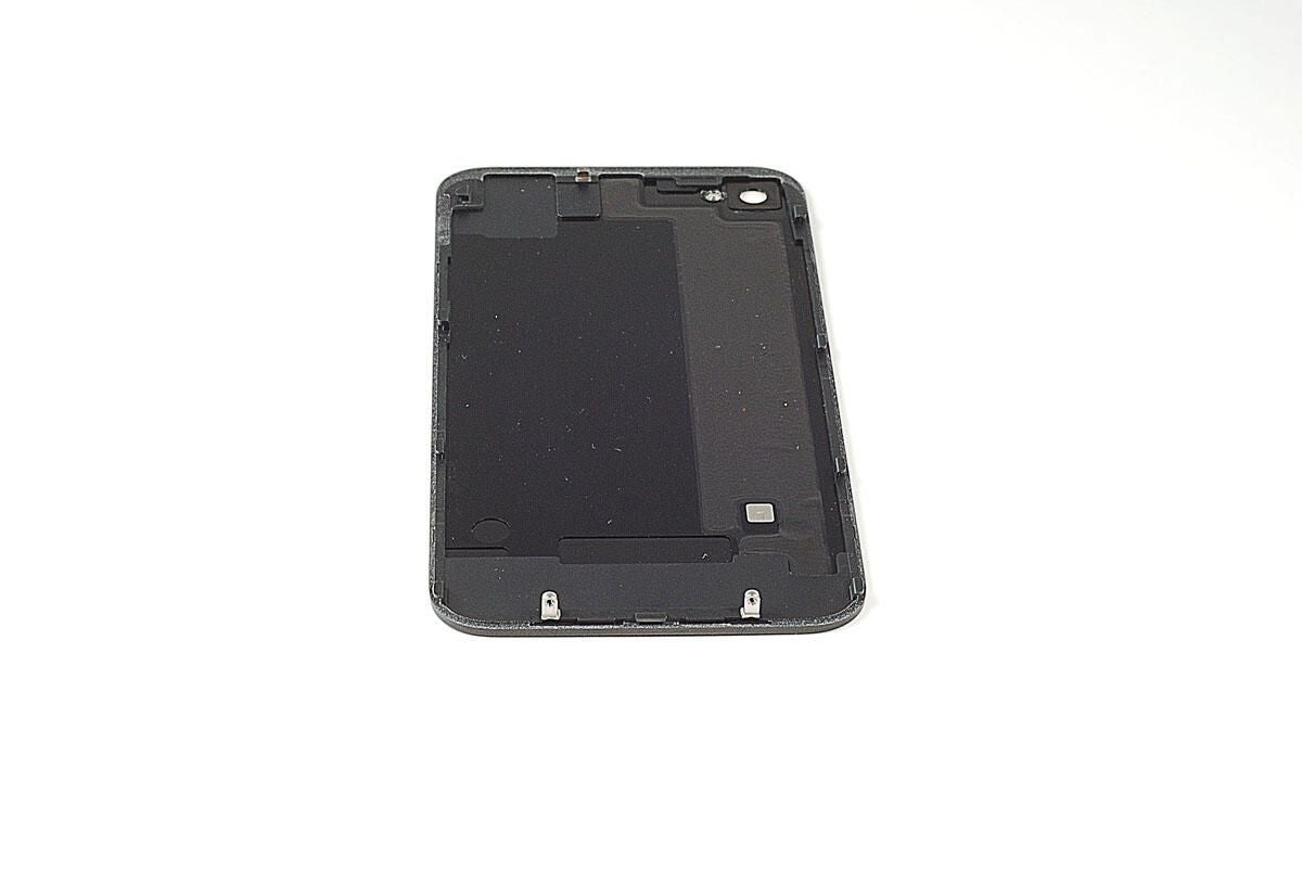
\n\tUsing a thin metal blade, I was able to pop the back cover away from the display assembly.
\n
\n\tPhoto by: Bill Detwiler / TechRepublic
\n\tCaption by: Bill Detwiler
\n\tAs I popped off the back cover, the speaker grils (thin pieces of plastic) began to come loose from the display assembly.
\n
\n\tPhoto by: Bill Detwiler / TechRepublic
\n\tCaption by: Bill Detwiler
\n\tInstead of having metal or even plastic speaker grills attached to the back cover or integrated with the speakers, the LY-706 uses extremely thin pieces of pliable plastic. This was the second indication that the device’s construction wasn’t on the same level as the Apple iPad or Samsung Galaxy tab.
\n
\n\tPhoto by: Bill Detwiler / TechRepublic
\n\tCaption by: Bill Detwiler
\n\tAs I removed the LY-706’s back cover, I heard something rattling inside. The culprit was a small Phillips screw that should have been helping hold the main PCB in place.
\n
\n\tPhoto by: Bill Detwiler / TechRepublic
\n\tCaption by: Bill Detwiler
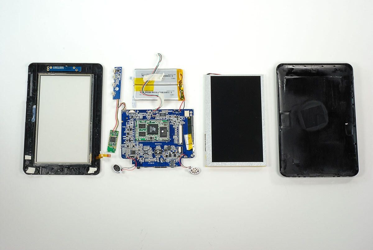
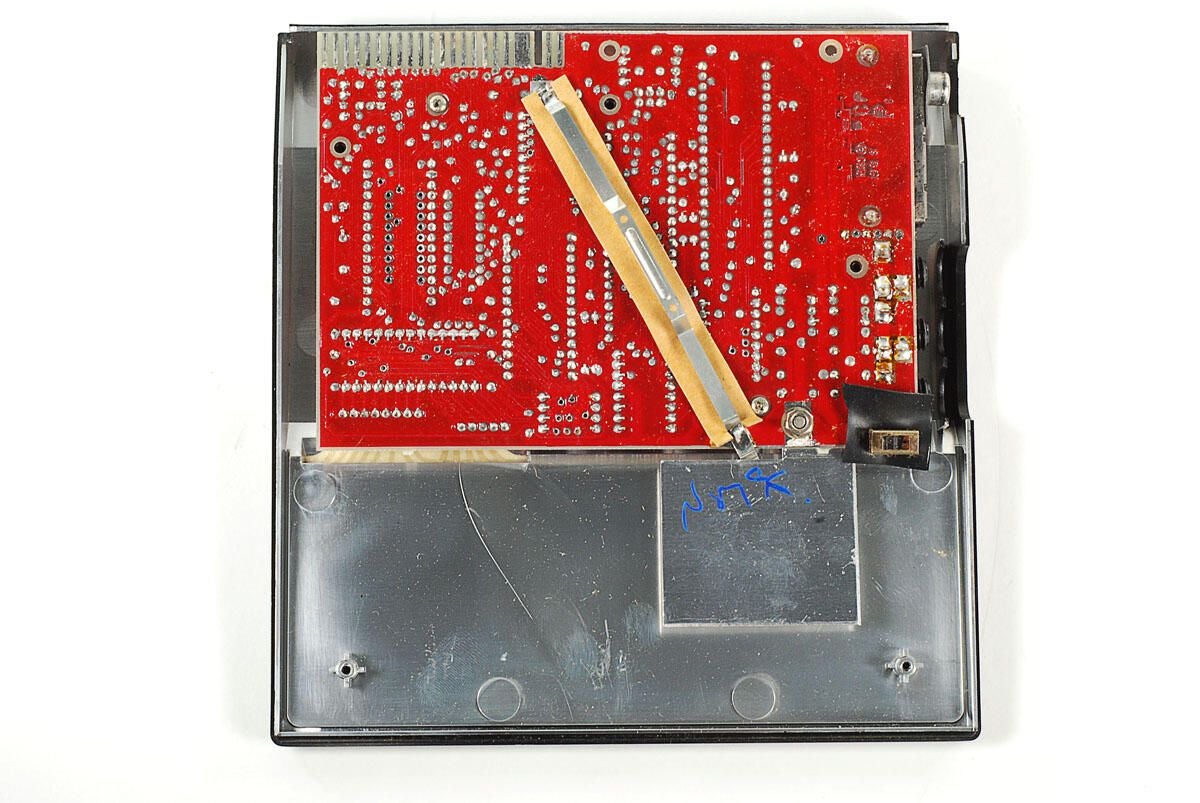
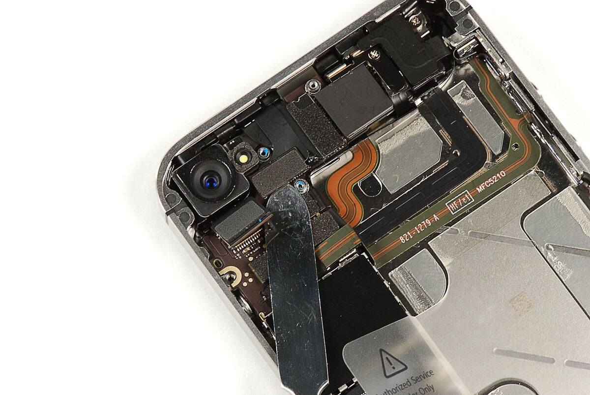
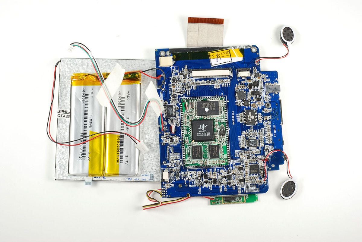
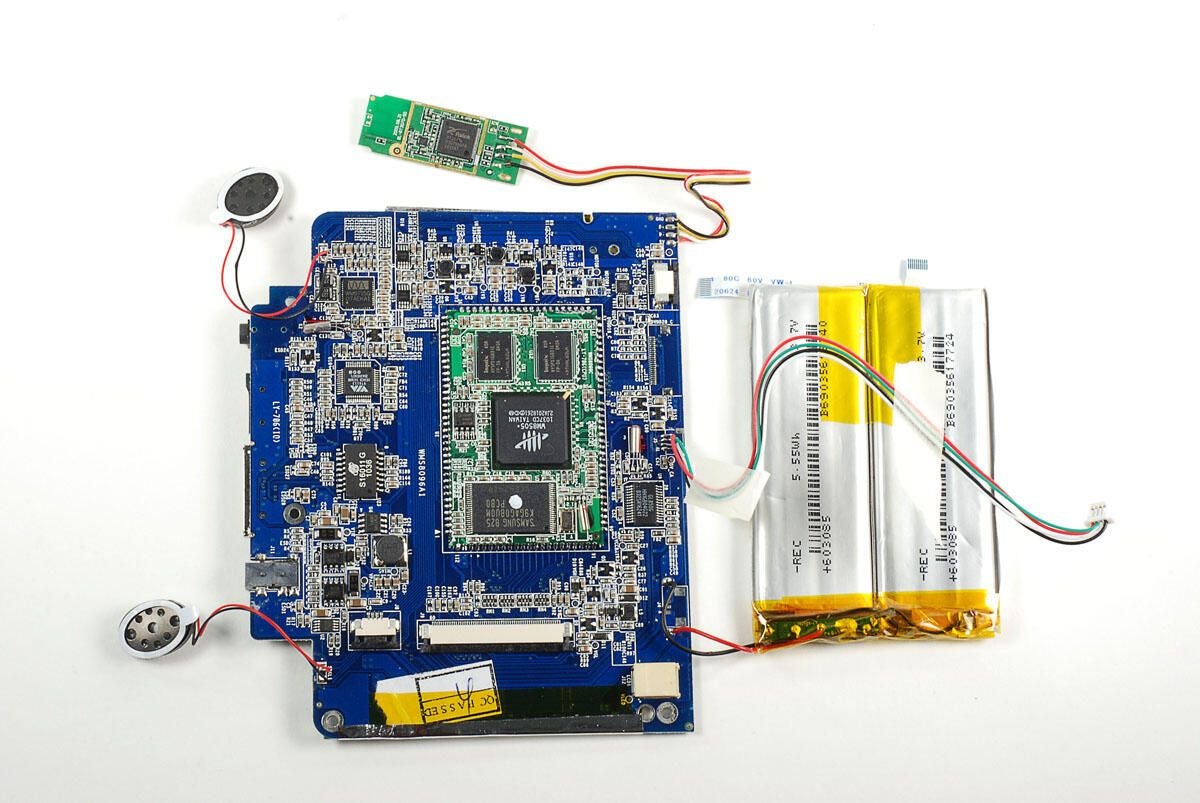
\n\tInside the LY-706, we find the main PCB (right side), a small PCB the holds the camera (left side), a small PCB that holds the right side buttons and microphone, a small PCB that holds the wireless chip, battery pack, and display.
\n
\n\tUnfortunately, many of the internal components are soldered to the main PCB. We’ll need to remove them and the main PCB as a single unit.
\n
\n\tPhoto by: Bill Detwiler / TechRepublic
\n\tCaption by: Bill Detwiler
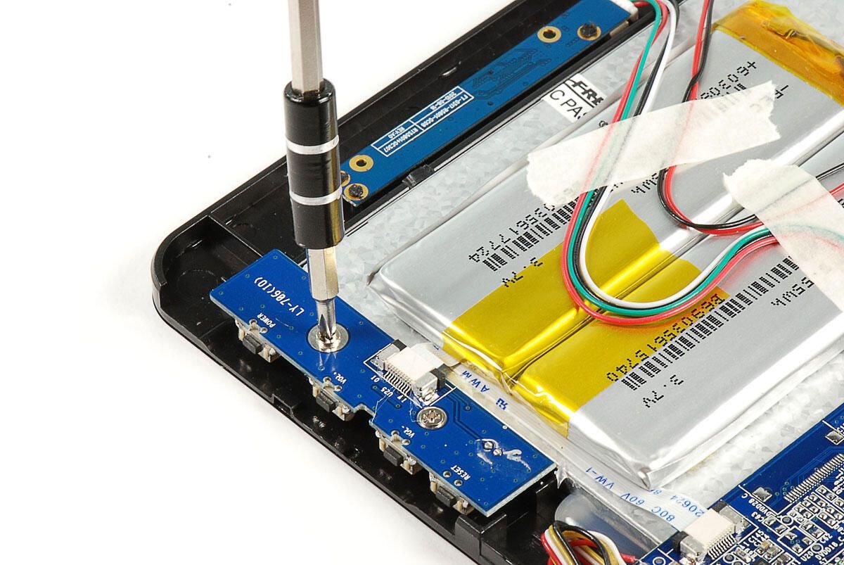
\n\tWe’ll start dissecting the LY-706’s internal components, by removing the small PCB that houses the right-side buttons and microphone. It is held to the front half of the plastic case with two Phillips screws.
\n
\n\tPhoto by: Bill Detwiler / TechRepublic
\n\tCaption by: Bill Detwiler
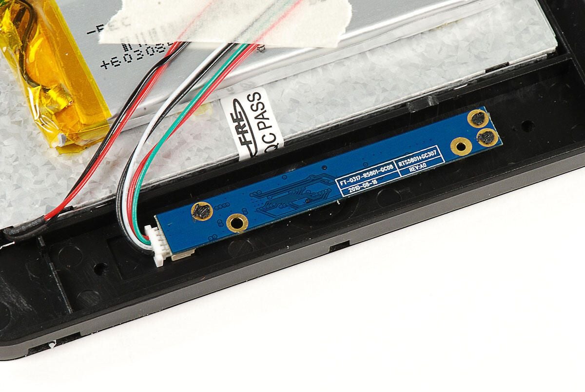
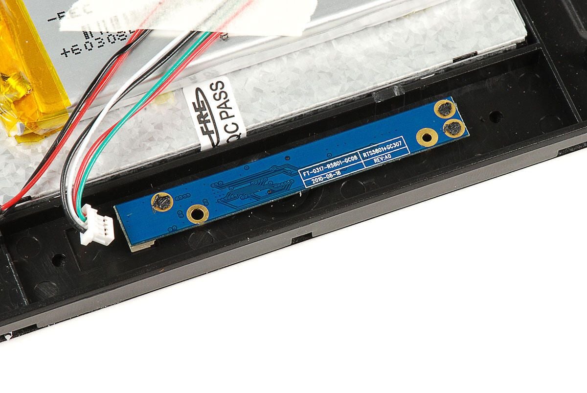
\n\tOnce the screws are removed, you can release the catch on the ribbon cable connector and lift the small PCB away from the LY-706 tablet.
\n
\n\tPhoto by: Bill Detwiler / TechRepublic
\n\tCaption by: Bill Detwiler
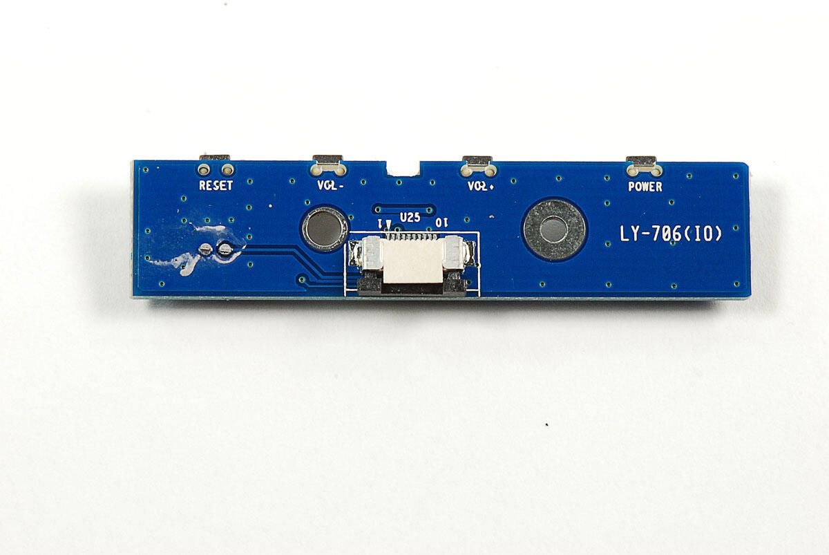
\n\tEach of the buttons on this small PCB are labled. From left to right are the reset, volume down, volume up, and power buttons.
\n
\n\tPhoto by: Bill Detwiler / TechRepublic
\n\tCaption by: Bill Detwiler
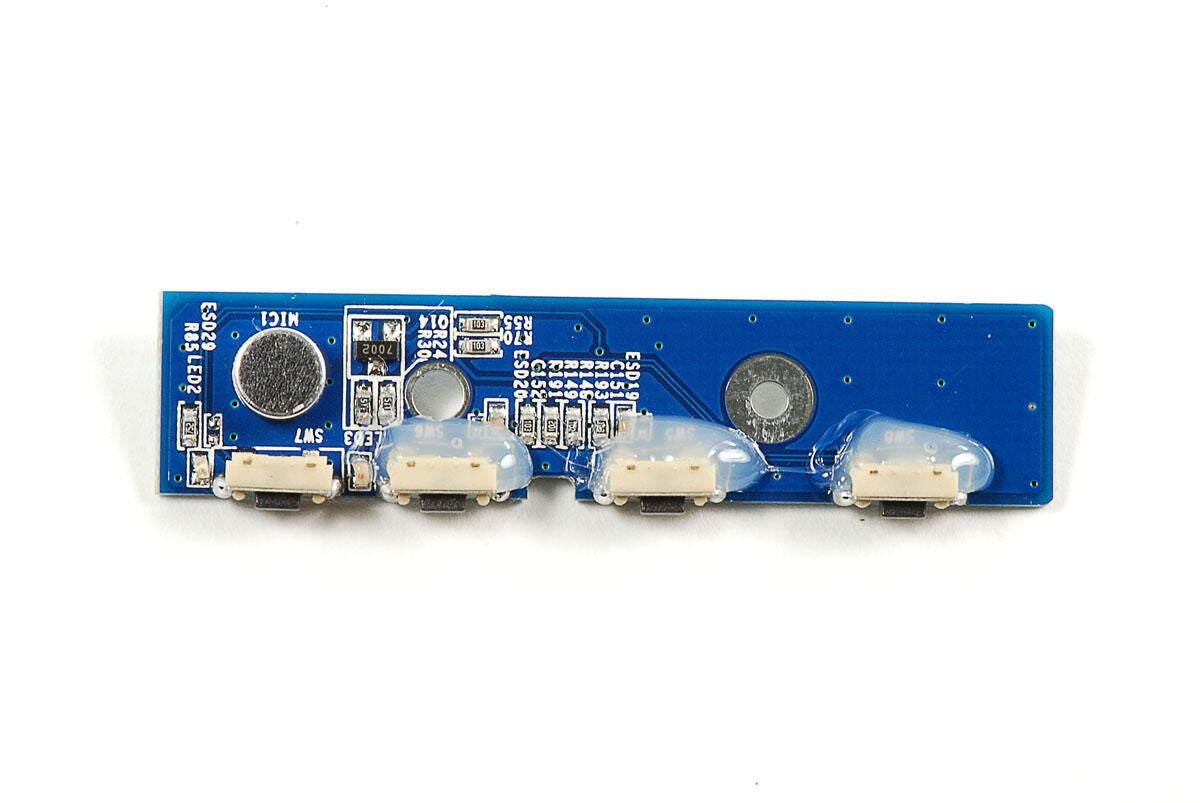
\n\tFlipping the right-side button PCB over, we see the actual buttons and the microphone.
\n
\n\tPhoto by: Bill Detwiler / TechRepublic
\n\tCaption by: Bill Detwiler
\n\tAnother small PCB contains the LY-706’s front-facing 1.3MP camera. Unfortunately, the PCB is permanently attached to the front case. I could remove the board, but it would require breaking the connections that hold it to the case.
\n
\n\tI’m going to leave this PCB in place, but disconnect it from the main PCB.
\n
\n\tPhoto by: Bill Detwiler / TechRepublic
\n\tCaption by: Bill Detwiler
\n\tLuckily the wires that connect the main PCB and camera PCB are not soldered to the small board.
\n
\n\tPhoto by: Bill Detwiler / TechRepublic
\n\tCaption by: Bill Detwiler
\n\tNext, I’ll disconnect the other end of the thin ribbon cable the connects the right-side button PCB to the motherboard.
\n
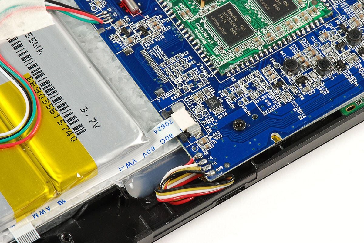
\n\tWe’ve already removed the right-side button PCB, but this ribbon cable is also attached to the underside of the battery pack. Disconnecting this end may make it eaiser to remove the main PCB later.
\n
\n\tPhoto by: Bill Detwiler / TechRepublic
\n\tCaption by: Bill Detwiler
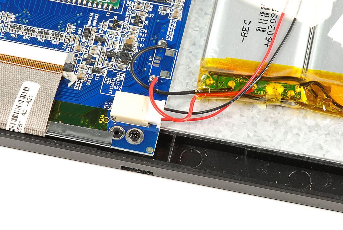
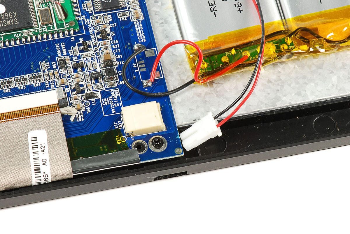
\n\tNext to the battery wires, which are soldered to the main PCB, is a connector with red and black wires that run to the LCD. There are likely wires for the backlight on the LCD.
\n
\n\tPhoto by: Bill Detwiler / TechRepublic
\n\tCaption by: Bill Detwiler
\n\tPhoto by: Bill Detwiler / TechRepublic
\n\tCaption by: Bill Detwiler
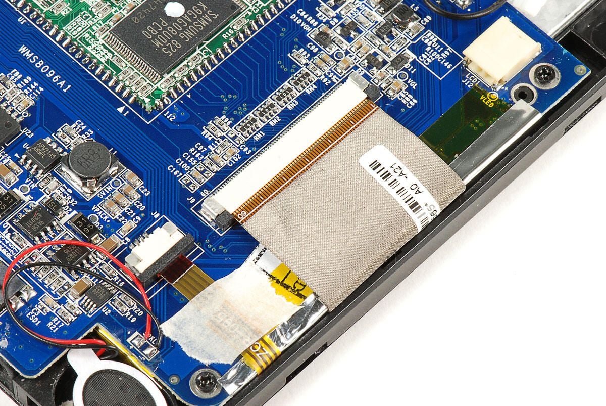
\n\tThe last two cables to disconnect are for the LCD (wided, gray ribbon cable) and resistive touchscreen (narrower, yellow ribbon cable).
\n
\n\tPhoto by: Bill Detwiler / TechRepublic
\n\tCaption by: Bill Detwiler
\n\tPhoto by: Bill Detwiler / TechRepublic
\n\tCaption by: Bill Detwiler
\n\tAfter disconnecting the ribbon cables, I bent them back slightly to make the main PCB easier to remove.
\n
\n\tPhoto by: Bill Detwiler / TechRepublic
\n\tCaption by: Bill Detwiler
\n\tI’ll also need to remove the tape that holds the LCD backlight wires to the battery pack.
\n
\n\tPhoto by: Bill Detwiler / TechRepublic
\n\tCaption by: Bill Detwiler
\n\tPhoto by: Bill Detwiler / TechRepublic
\n\tCaption by: Bill Detwiler
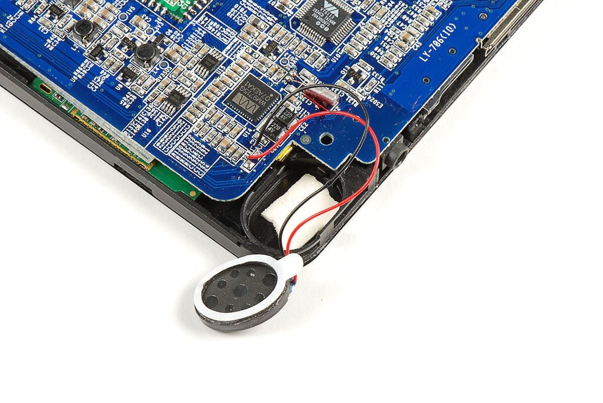
\n\tThe LY-706’s two internal speakers are soldered to the motherboard. We’ll need to separate them from the the plastic case before removing the main PCB.
\n
\n\tUsing a thin metal blade, you can gently pry them loose from the adhesive tape that holds them in place.
\n
\n\tPhoto by: Bill Detwiler / TechRepublic
\n\tCaption by: Bill Detwiler
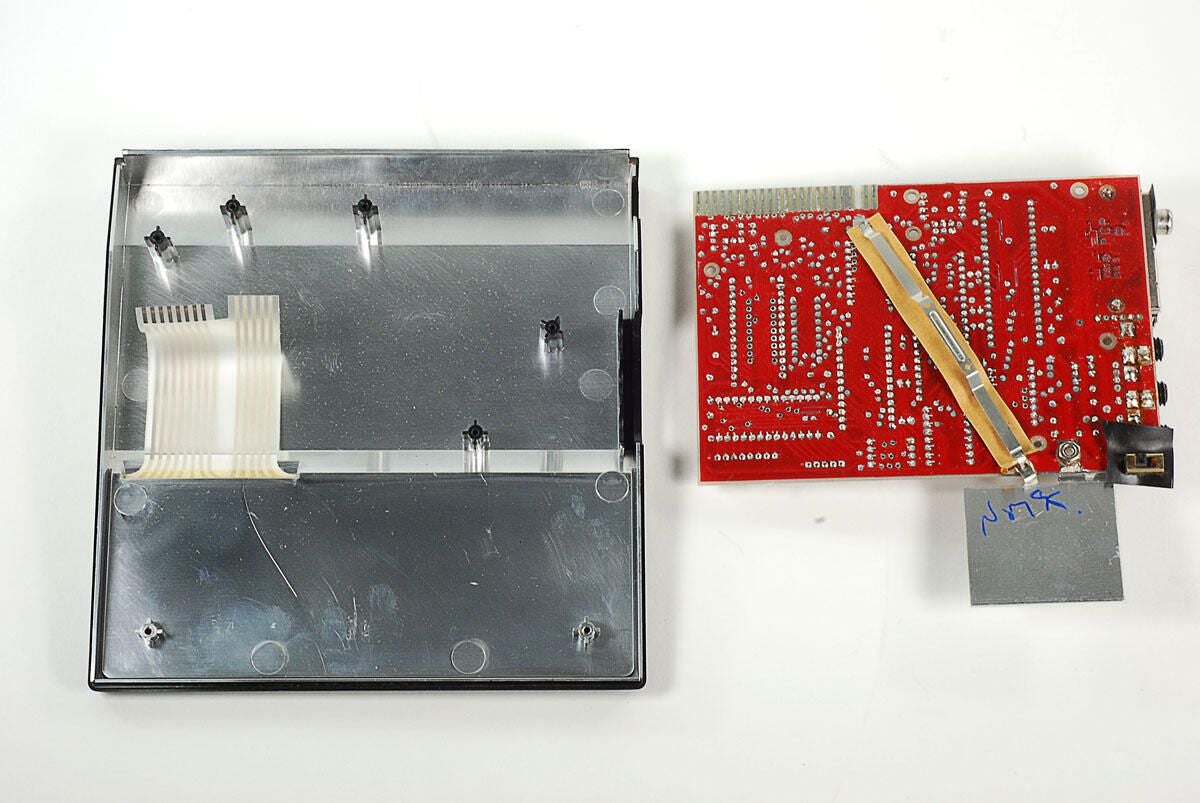
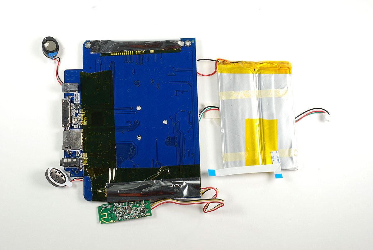
\n\tWith all the internal cables, screws, and stuck components free, we can begin to lift the LCD, main PCB, and attached components away from the front half of the LY-706’s case.
\n
\n\tPhoto by: Bill Detwiler / TechRepublic
\n\tCaption by: Bill Detwiler
\n\tPhoto by: Bill Detwiler / TechRepublic
\n\tCaption by: Bill Detwiler
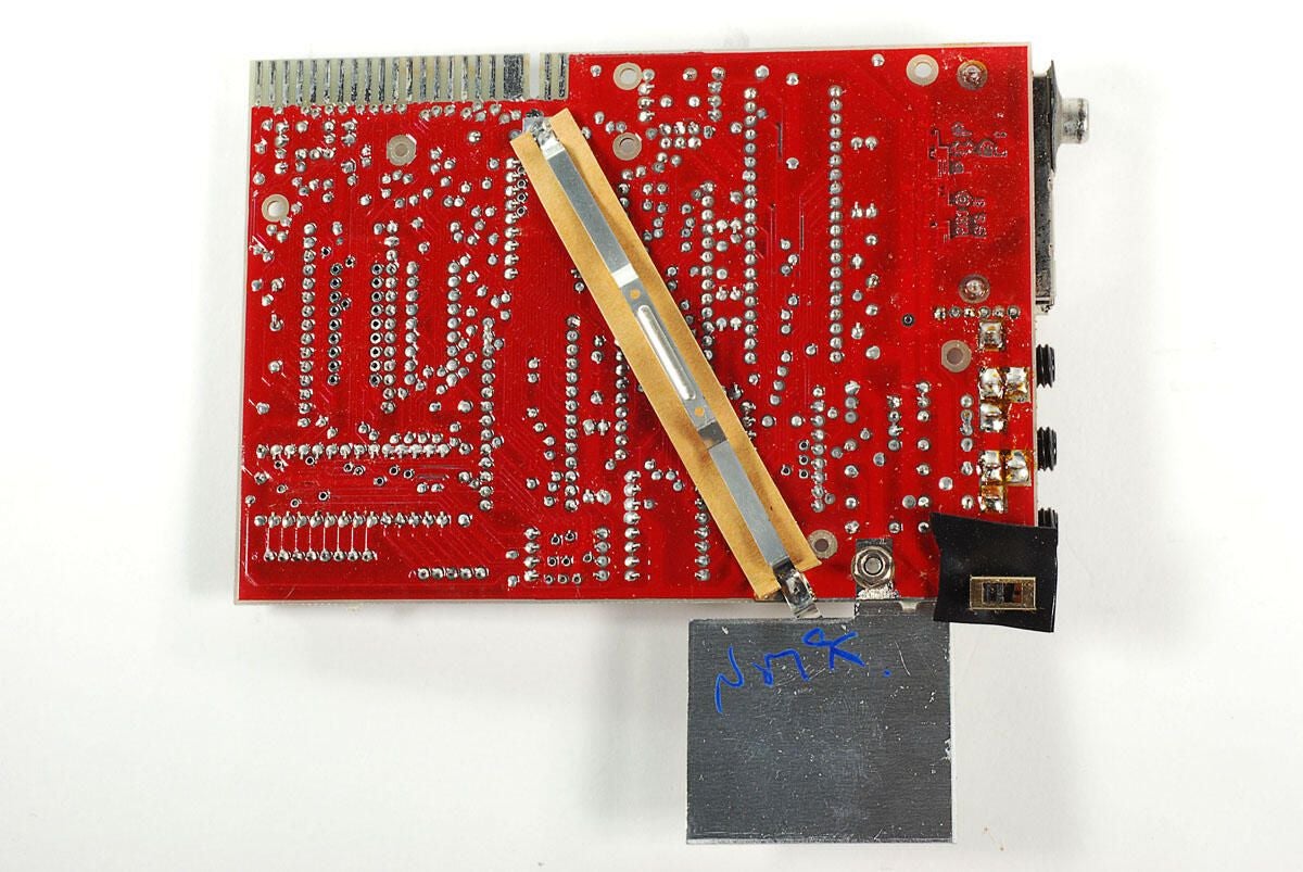
\n\tA smaller, green PCB is attached to the front case panel and located under the main PCB. It’s wires are soldered to the main PCB, so we’ll need to remove it from the front case panel.
\n
\n\tPhoto by: Bill Detwiler / TechRepublic
\n\tCaption by: Bill Detwiler
\n\tPhoto by: Bill Detwiler / TechRepublic
\n\tCaption by: Bill Detwiler
\n\tPhoto by: Bill Detwiler / TechRepublic
\n\tCaption by: Bill Detwiler
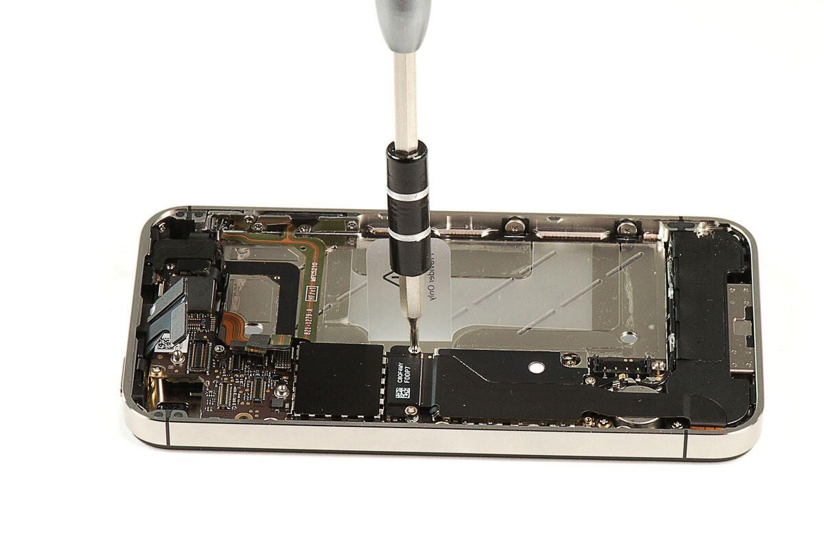
\n\tWith most of the internal components removed, we can see the LY-706’s resistive touchscreen.
\n
\n\tPhoto by: Bill Detwiler / TechRepublic
\n\tCaption by: Bill Detwiler
\n\tUnlike nearly all the smartphones and tablets I’ve cracked open, the LY-706 use a touchscreen made from layers of thin, flexible plastic instead of glass. Here you can see me peeling a corner of the top layer away from the front case’s hard plastic edge.
\n
\n\tPhoto by: Bill Detwiler / TechRepublic
\n\tCaption by: Bill Detwiler
\n\tI’m not really sure what this wad of glue was designed to hold in place.
\n
\n\tPhoto by: Bill Detwiler / TechRepublic
\n\tCaption by: Bill Detwiler
\n\tThe LY-706’s battery back is attached to the back of the LCD with adhesive. Next, we’ll need to separate the two.
\n
\n\tPhoto by: Bill Detwiler / TechRepublic
\n\tCaption by: Bill Detwiler
\n\tUsing a thin blade, I was able to slice through the adhesive that holds the battery pack to the back of the LCD.
\n
\n\tPhoto by: Bill Detwiler / TechRepublic
\n\tCaption by: Bill Detwiler
\n\tThere are no markings on the LCD that indicate who made it. (At least none that I could find.) But, there are a few markings on the ribbon cable and a sticker attached to the cable.
\n
\n\tPhoto by: Bill Detwiler / TechRepublic
\n\tCaption by: Bill Detwiler
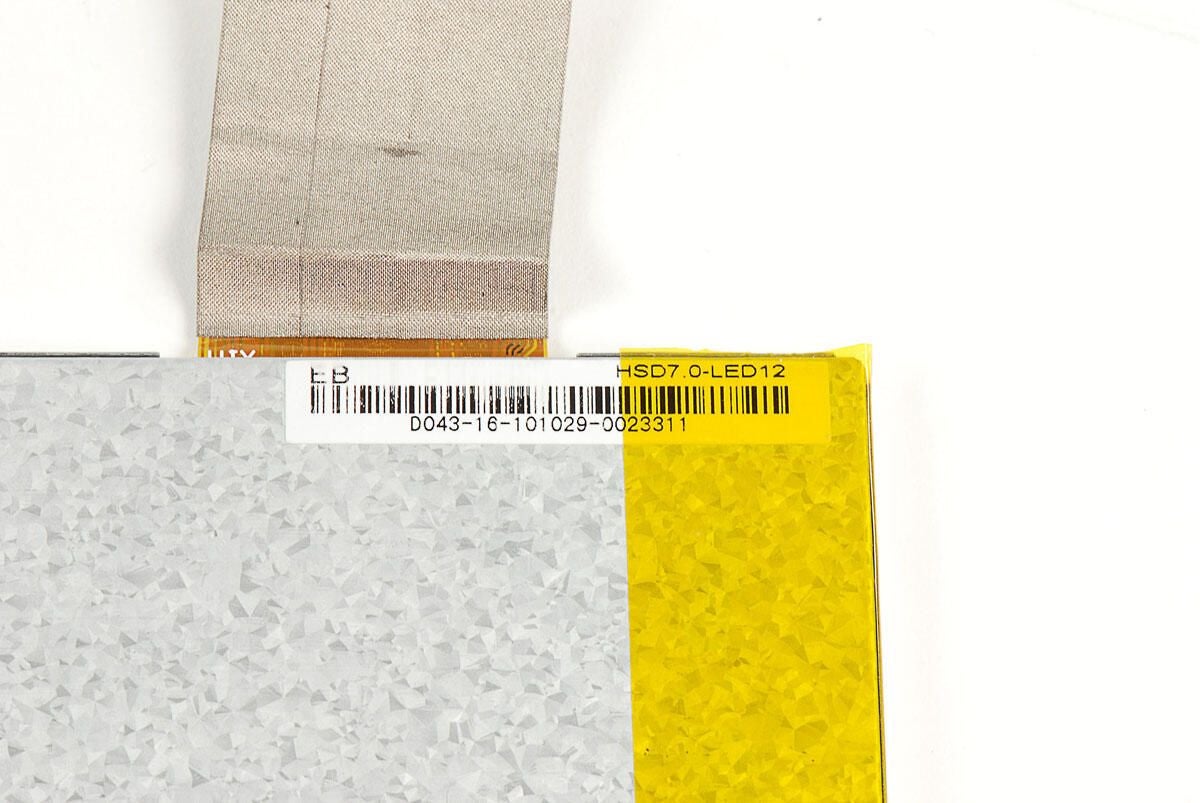
\n\tA sticker on the back of the LCD unit reads:
\n
\n\tEB
\n
\n\tHSD7.0-LED12
\n
\n\tD043-16-101029-0023311
\n
\n\tPhoto by: Bill Detwiler / TechRepublic
\n\tCaption by: Bill Detwiler
\n\tThe wireless PCB, battery pack, and speakers are soldered to the main PCB.
\n
\n\tPhoto by: Bill Detwiler / TechRepublic
\n\tCaption by: Bill Detwiler
\n\tPhoto by: Bill Detwiler / TechRepublic
\n\tCaption by: Bill Detwiler
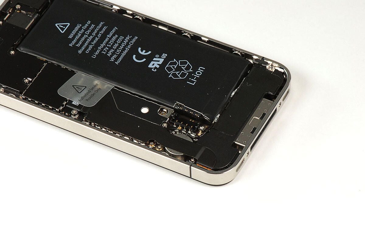
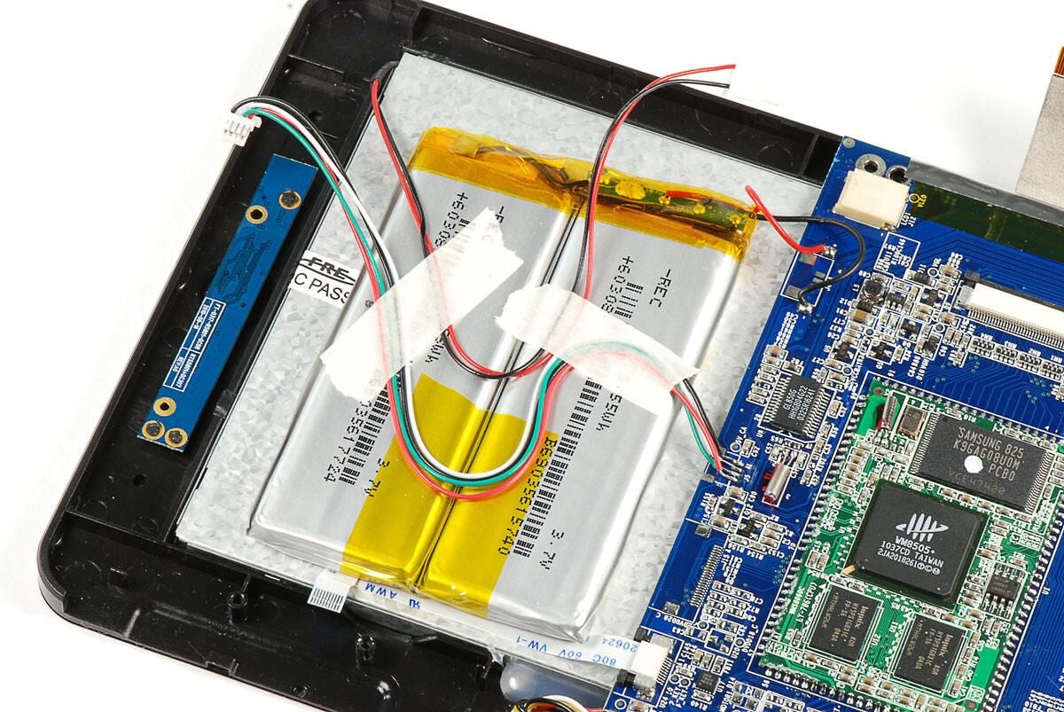
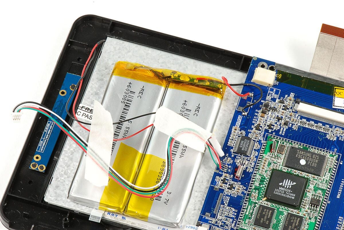
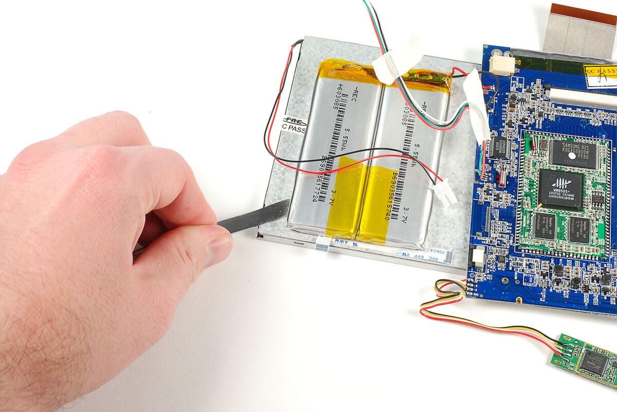
\n\tThe LY-706 has a battery pack with two 3.7V 5.55Wh batteries. I’ve read several complaints about the device having extremely poor battery life. And, TechRepublic’s own Mark Kaelin reported getting only two hours of battery life under normal use.
\n
\n\tFor the record, neither the FocalPrice site nor the documentation included with the LY-706 lists an average battery life.
\n
\n\tPhoto by: Bill Detwiler / TechRepublic
\n\tCaption by: Bill Detwiler
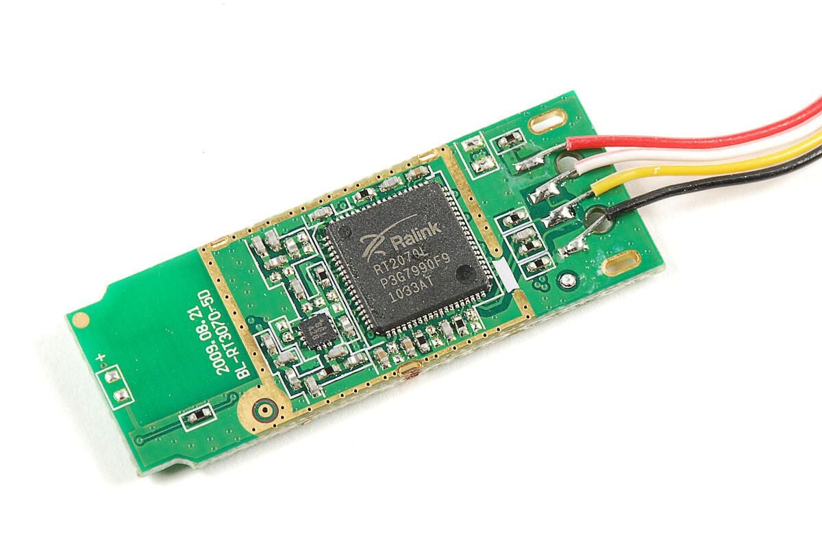
\n\tThe LY-706 provides Wi-Fi support through a Ralink RT2070L 802.11n Wireless LAN USB Adapter. The RT2070L appears to be one of Ralink’s older, discontinued chips.
\n
\n\tOddly enough, the small PCB to which the IC is mounted has the markings for the Ralink RT3070–one of the company’s newer Wi-Fi ICs.
\n
\n\tPhoto by: Bill Detwiler / TechRepublic
\n\tCaption by: Bill Detwiler
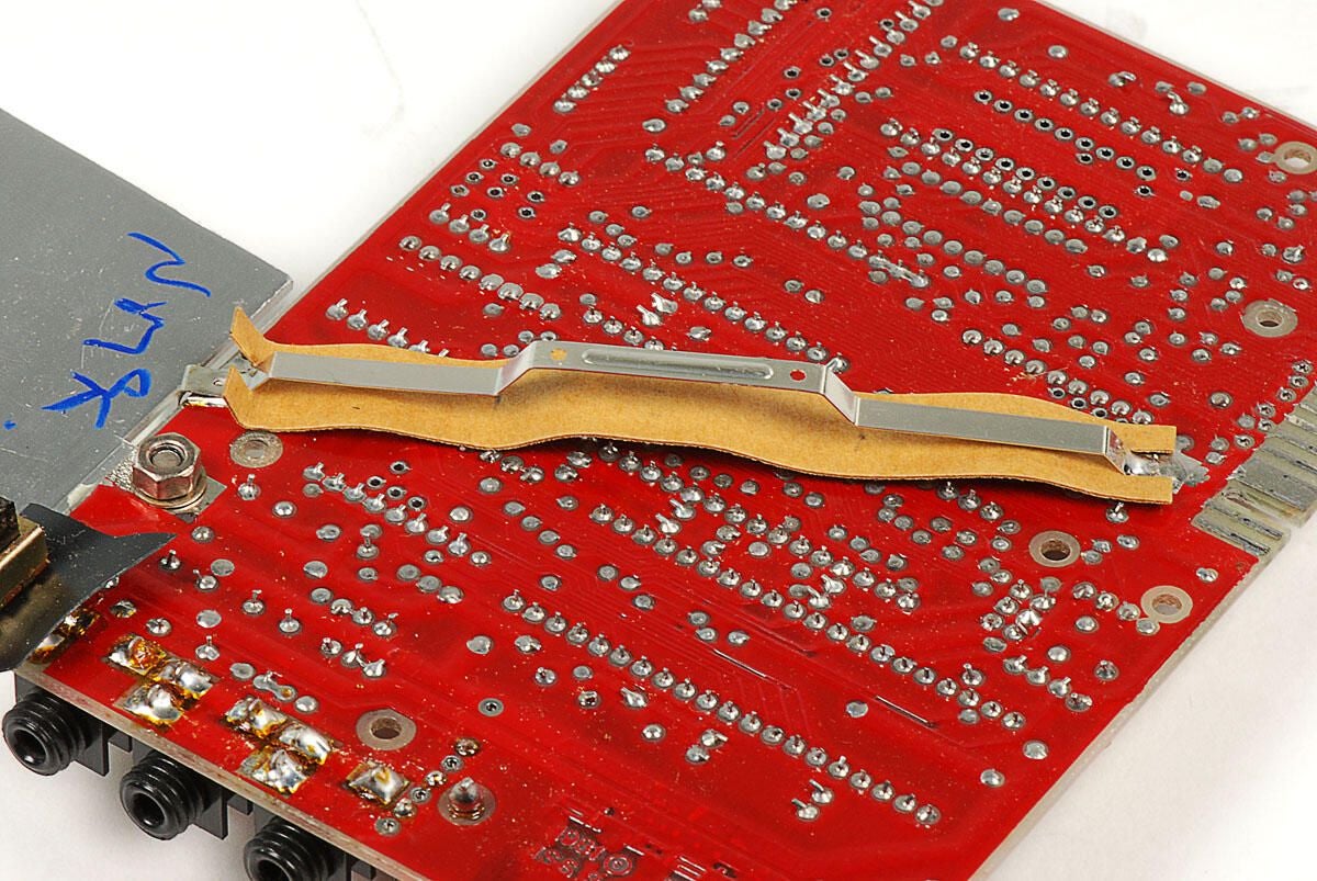
\n\tThere don’t appear to be any antenna wires mounted inside the LY-706.
\n
\n\tPhoto by: Bill Detwiler / TechRepublic
\n\tCaption by: Bill Detwiler
\n\tThe LY-706 has a single Samsung 2GB NAND Flash chip (K9GAG08U0M) for storage.
\n
\n\tPhoto by: Bill Detwiler / TechRepublic
\n\tCaption by: Bill Detwiler
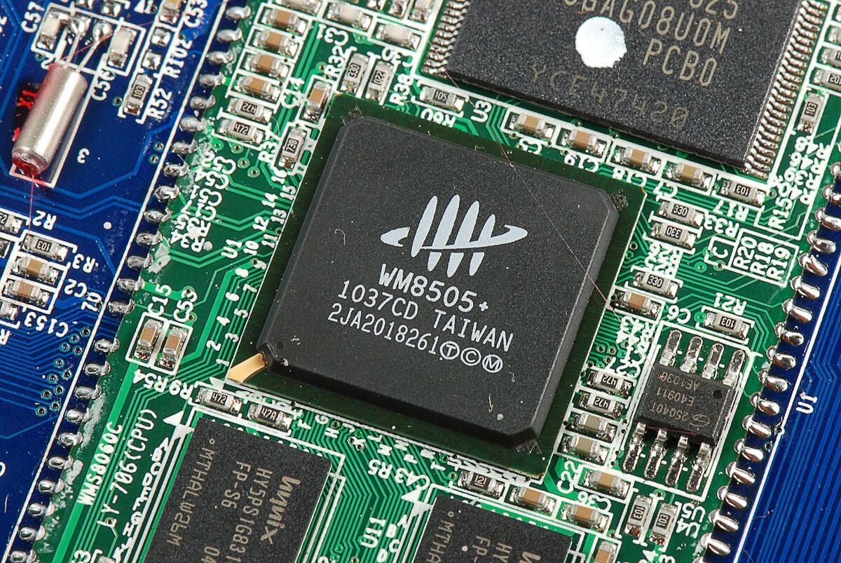
\n\tThe LY-706 is powered by VIA Technolgoy’s WonderMedia WM8505 ARM-based CPU. Unfortunately, I wasn’t able to find a clock speed for the specific chip used in this device. I’ve read reports of number ranging between 300MHz and 600MHz.
\n
\n\tPhoto by: Bill Detwiler / TechRepublic
\n\tCaption by: Bill Detwiler
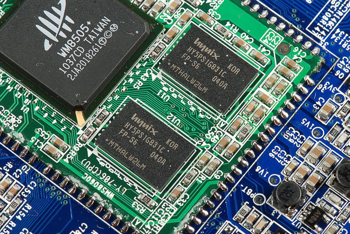
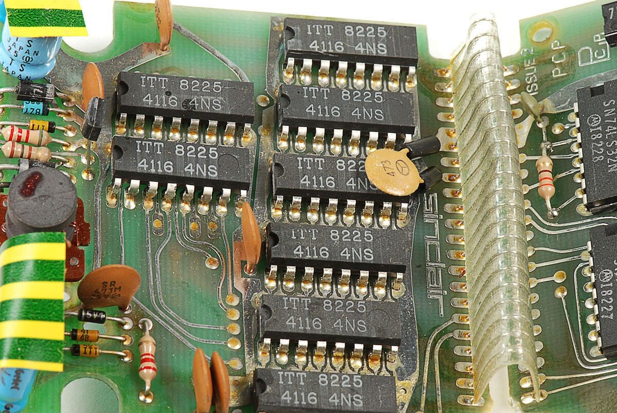
\n\tThe LY-706 has two Hynix DDR SDRAM modules (HY5PS1G831C). According to the product specs, the device has 256MB of system memory. But according to Hynix’s online documentation, these modules only come in 1GB and 2GB configurations.
\n
\n\tPhoto by: Bill Detwiler / TechRepublic
\n\tCaption by: Bill Detwiler
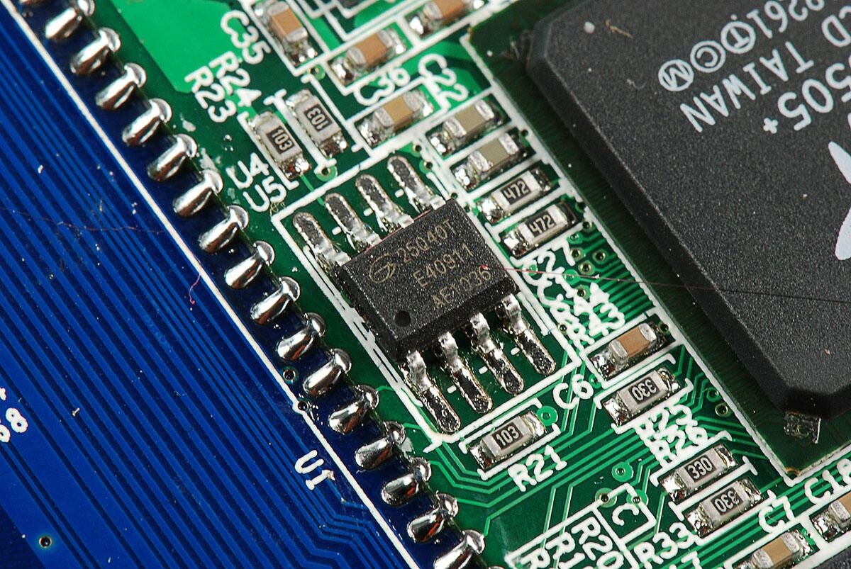
\n\tChips with markings:
\n
\n\t25040T
\n
\n\tE40911
\n
\n\tAE1036
\n
\n\tPhoto by: Bill Detwiler / TechRepublic
\n\tCaption by: Bill Detwiler
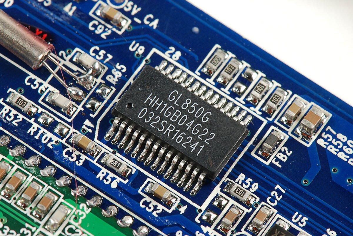
\n\tGenesys Logic GL850G USB hub controller
\n
\n\tPhoto by: Bill Detwiler / TechRepublic
\n\tCaption by: Bill Detwiler
\n\tChip with markings:
\n
\n\tS16011G
\n
\n\t1036
\n
\n\tPhoto by: Bill Detwiler / TechRepublic
\n\tCaption by: Bill Detwiler
\n\tWolfson Micro WM9715 CODEC with touchpanel controller
\n
\n\tPhoto by: Bill Detwiler / TechRepublic
\n\tCaption by: Bill Detwiler
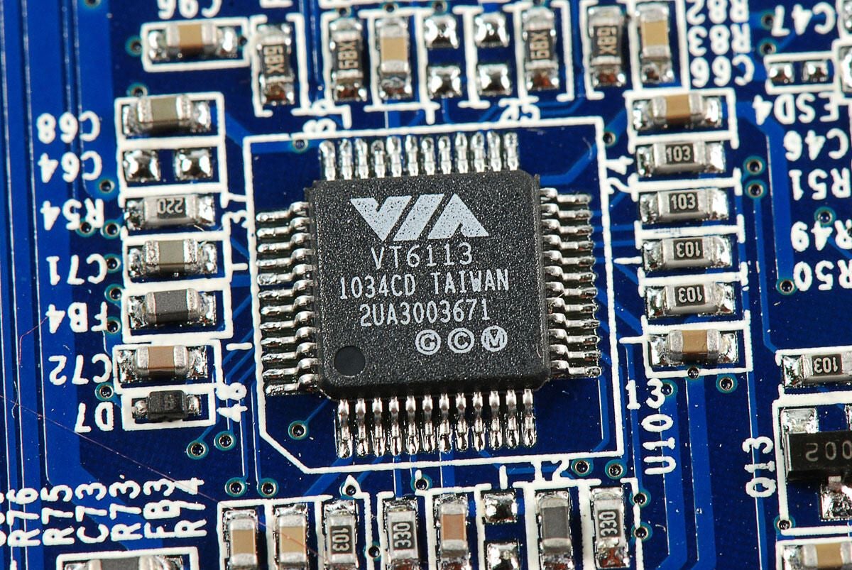
\n\tVIA VT6113 10/100 Ethernet controller
\n
\n\tPhoto by: Bill Detwiler / TechRepublic
\n\tCaption by: Bill Detwiler
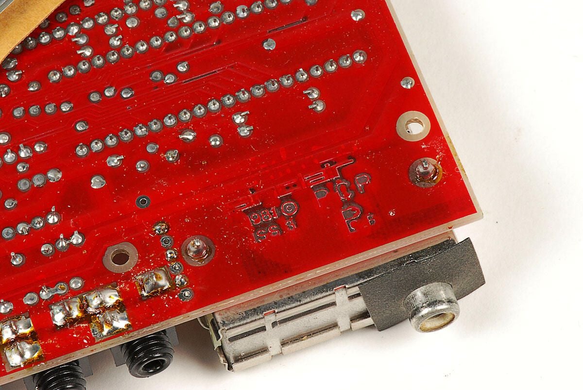
\n\tI looked all over the PCB for a marking that would indicate who assembled the LY-706, or at least manufactured the motherboard, but I only found two markings of note.
\n
\n\tThe one show in this photo is the device’s model number: LY-706(IO)
\n
\n\tPhoto by: Bill Detwiler / TechRepublic
\n\tCaption by: Bill Detwiler
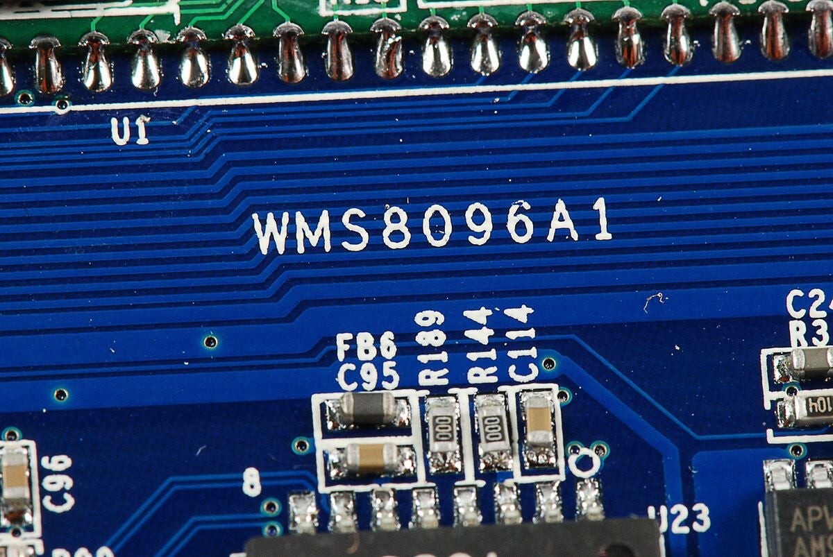
\n\tSecond main PCB markings: WMS8096A1
\n
\n\tPhoto by: Bill Detwiler / TechRepublic
\n\tCaption by: Bill Detwiler
Bill Detwiler is the Editor for Technical Content and Ecosystem at Celonis. He is the former Editor in Chief of TechRepublic and previous host of TechRepublic's Dynamic Developer podcast and Cracking Open, CNET and TechRepublic's popular online show. Previously, Bill was an IT manager in the social research and energy industries. He has bachelor's and master's degrees from the University of Louisville, where he has also lectured on computer crime and crime prevention.
