\n\tThe Amiga 2000 was designed to be the high-end version of the Amiga 500 and successor to the popular Amiga 1000.
\n
\n\tWe purchased this Commodore Amiga 2000 (B2000-CR) for about $200 from an online auction. It arrived without a keyboard, documentation, or software.
\n\t
\n\tPhoto by: Bill Detwiler / TechRepublic
\n\tCaption by: Bill Detwiler
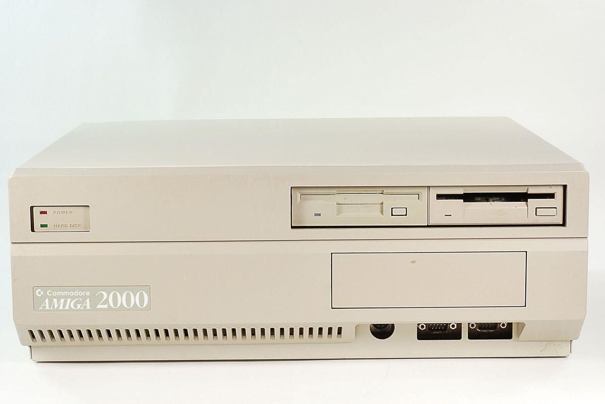
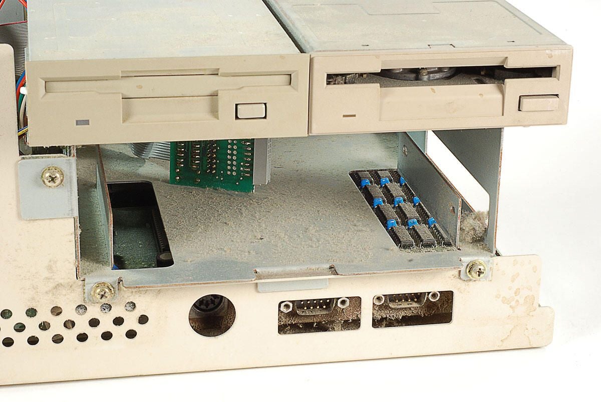
\n\tAlong the front of the Amiga 2000 are the power and hard disk activity lights, two bays for 3.5″ disk drives, one bay for a 5.25″ drive, 5-pin DIN femal keyboard port, and two DE-9 RS-232 serial ports (used for a mouse or other controller).
\n
\n\tPhoto by: Bill Detwiler / TechRepublic
\n\tCaption by: Bill Detwiler
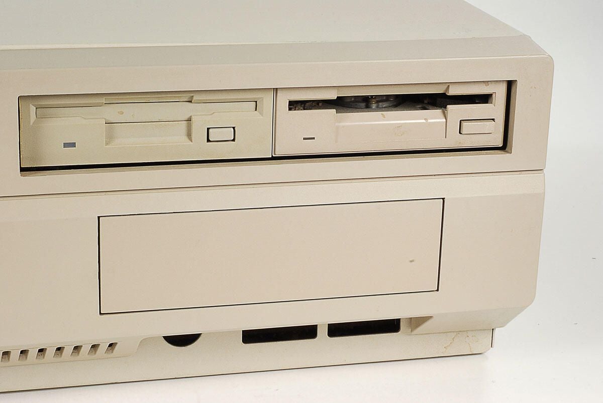
\n\tThe Amiga 2000 can accomodate two 3.5″ drives and a single 5.25″ drive. This unit has two 3.5″ drive, but no 5.25″ drive–thus the rectangular plastic panel below the two 3.5″ drives.
\n
\n\tPhoto by: Bill Detwiler / TechRepublic
\n\tCaption by: Bill Detwiler
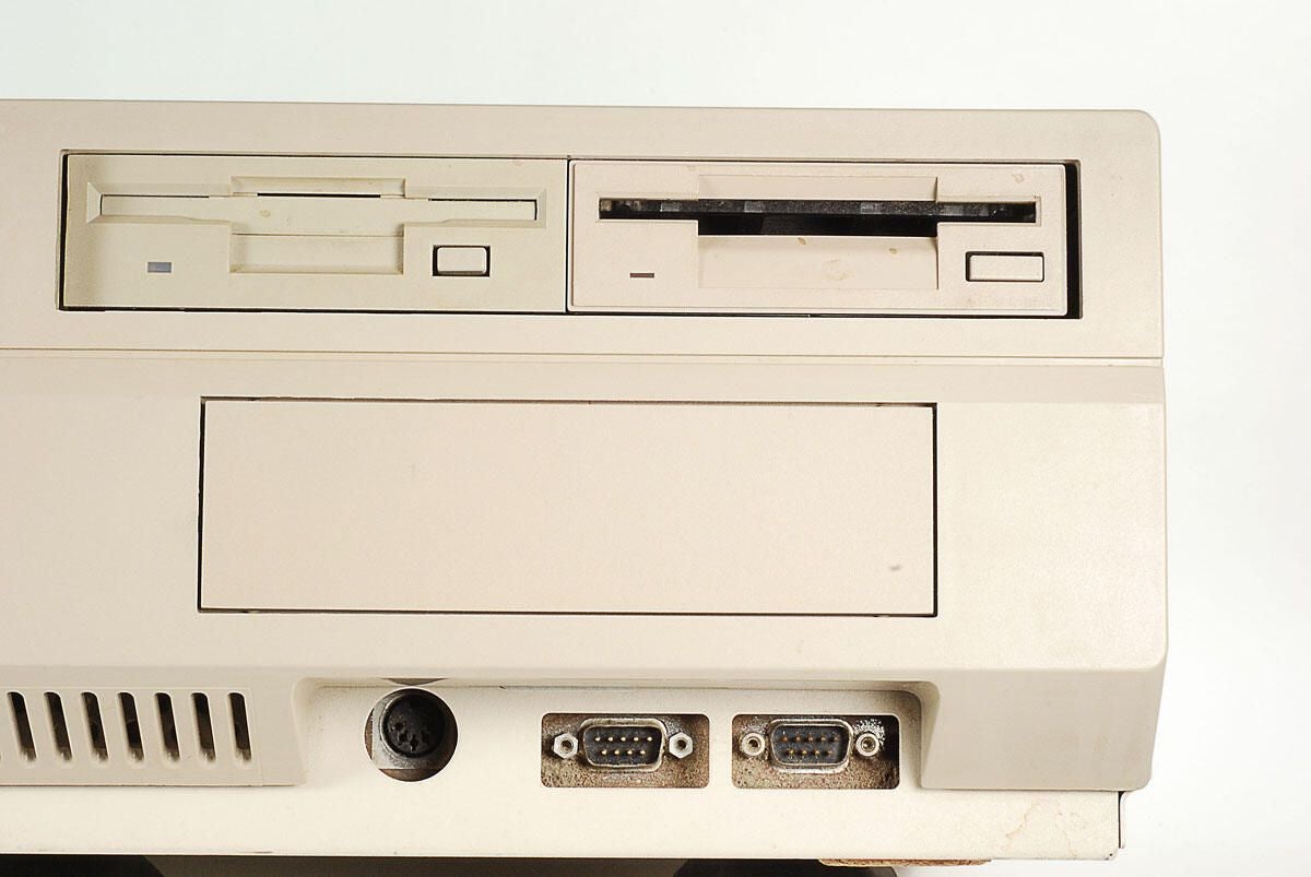
\n\tThe Amiga 2000 has a 5-pin DIN female keyboard port and two DE-9 RS-232 serial ports (for a mouse, joystick, or other controller).
\n
\n\tPhoto by: Bill Detwiler / TechRepublic
\n\tCaption by: Bill Detwiler
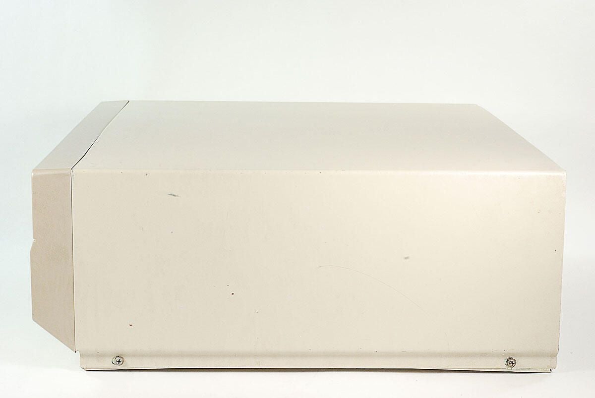
\n\tOther than the two case srews, there’s nothing of note on either side of the Amiga 2000.
\n
\n\tPhoto by: Bill Detwiler / TechRepublic
\n\tCaption by: Bill Detwiler
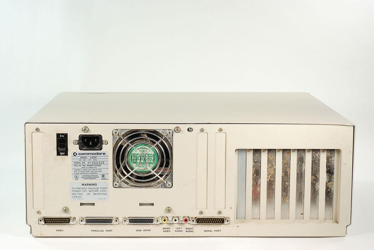
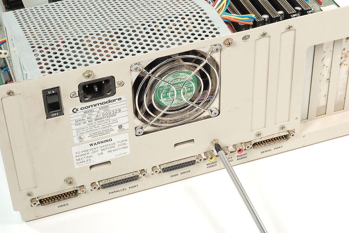
\n\tAlong the back of the Amiga 2000 are the power switch, C14 power inlet, power supply cooling fan vent, and external ports.
\n
\n\tPhoto by: Bill Detwiler / TechRepublic
\n\tCaption by: Bill Detwiler
\n\tPhoto by: Bill Detwiler / TechRepublic
\n\tCaption by: Bill Detwiler
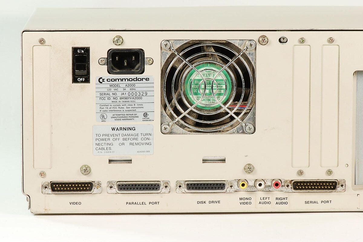
\n\tThe following ports are located on the back of the Amiga 2000:
\n
\n\t
\n\t
\n\t
\n\t
\n\t
\n
\n
\n\tPhoto by: Bill Detwiler / TechRepublic
\n\tCaption by: Bill Detwiler
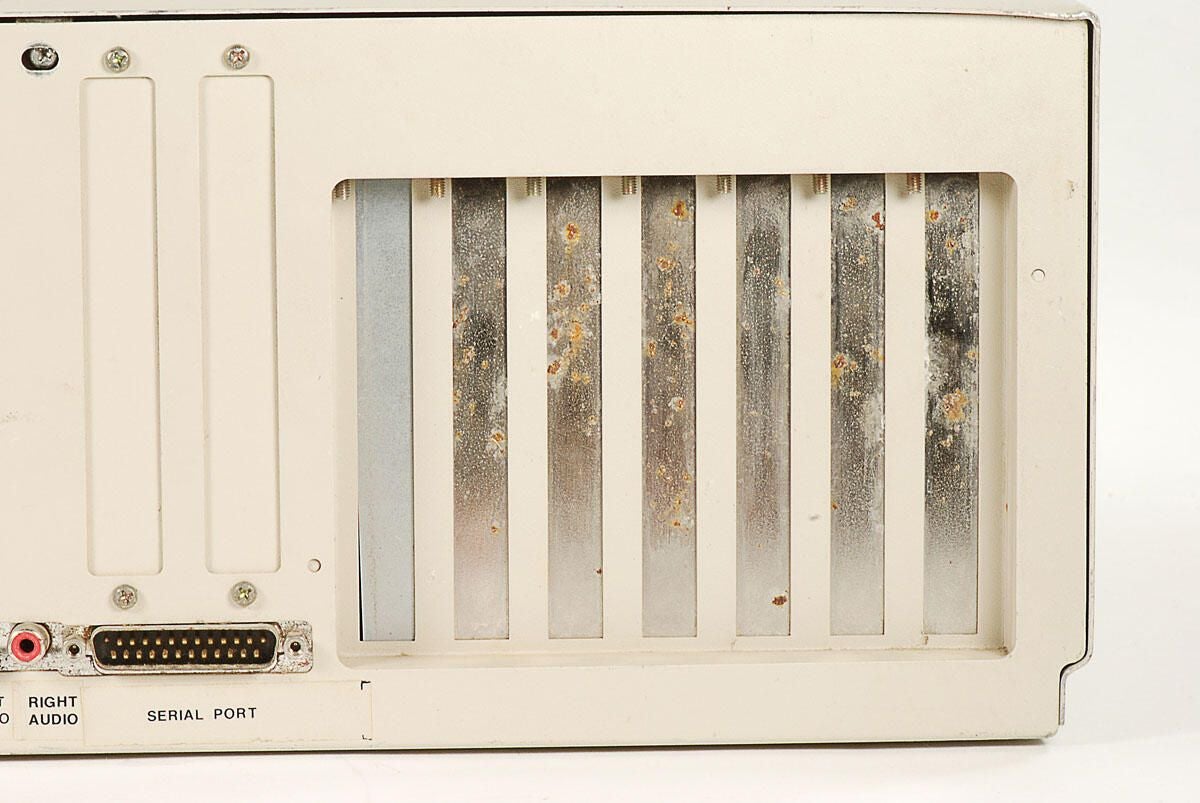
\n\tThe Amiga 2000 has nine expansion slots, broken down as follows:
\n
\n\t
\n\t
\n
\n
\n\tNone of the slots are being used on this machine.
\n
\n\tPhoto by: Bill Detwiler / TechRepublic
\n\tCaption by: Bill Detwiler
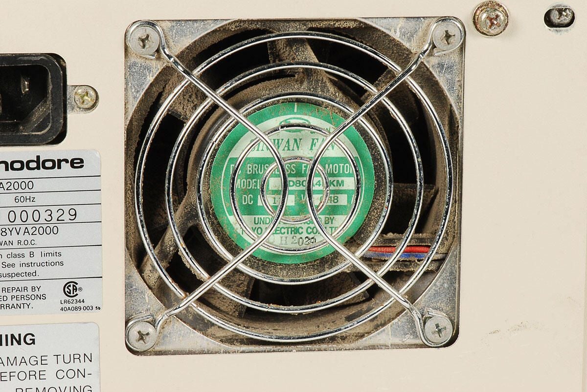
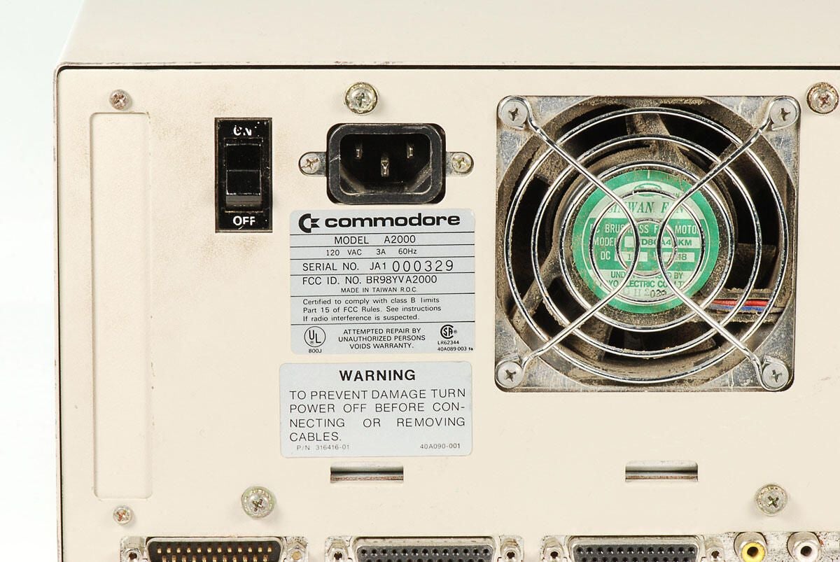
\n\tThere is a lot of dust on the inside of this Amiga 2000’s PSU cooling fan. This doesn’t bode well for the cleanlines of the other internal components.
\n
\n\tPhoto by: Bill Detwiler / TechRepublic
\n\tCaption by: Bill Detwiler
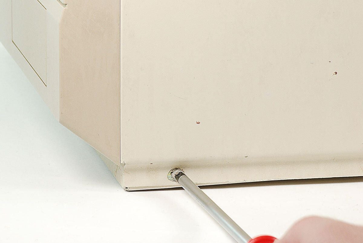
\n\tThe first step in cracking open this Amiga 2000 is to remove the two screws on each side of the metal case.
\n
\n\tPhoto by: Bill Detwiler / TechRepublic
\n\tCaption by: Bill Detwiler
\n\tPhoto by: Bill Detwiler / TechRepublic
\n\tCaption by: Bill Detwiler
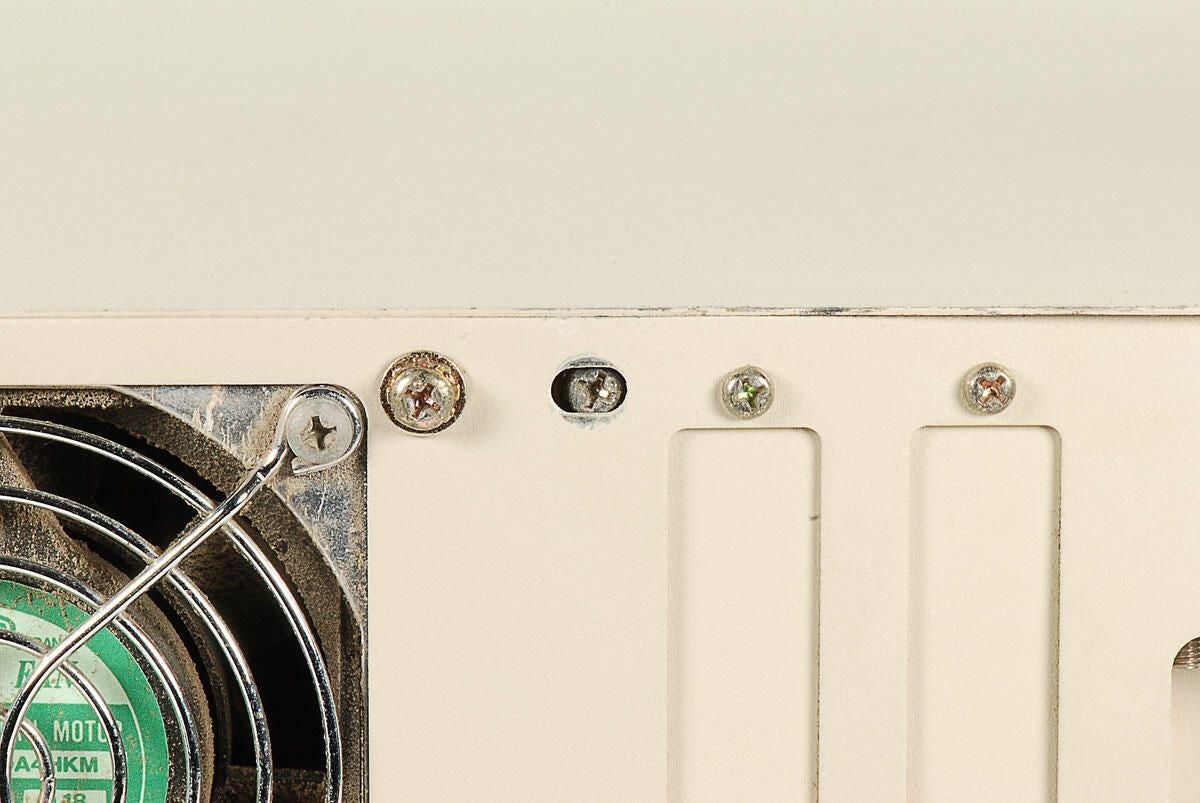
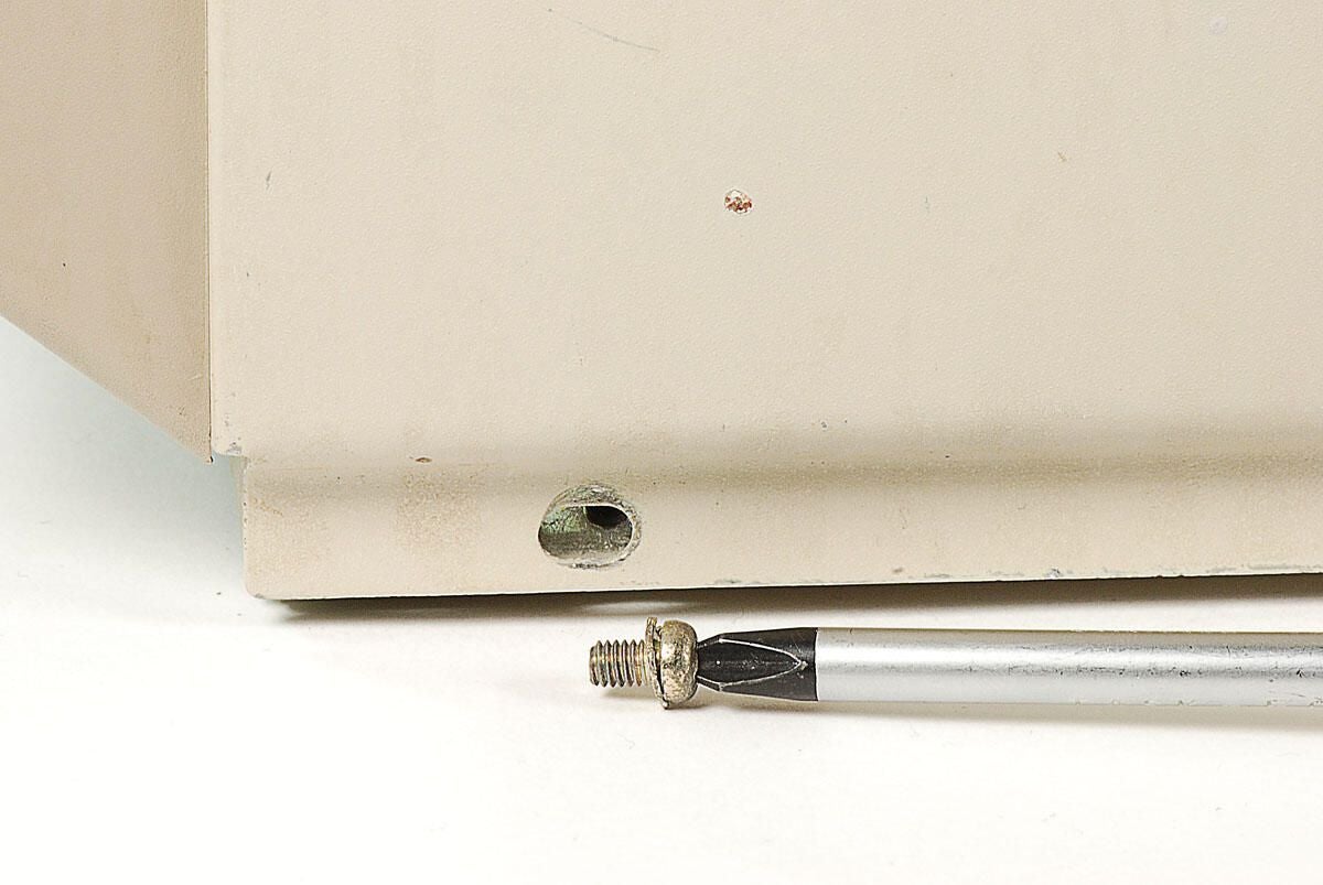
\n\tA single case screw is located on the back of the Amiga 2000. Unfortunately, someone installed this machine’s case without first removing the screw.
\n
\n\tPhoto by: Bill Detwiler / TechRepublic
\n\tCaption by: Bill Detwiler
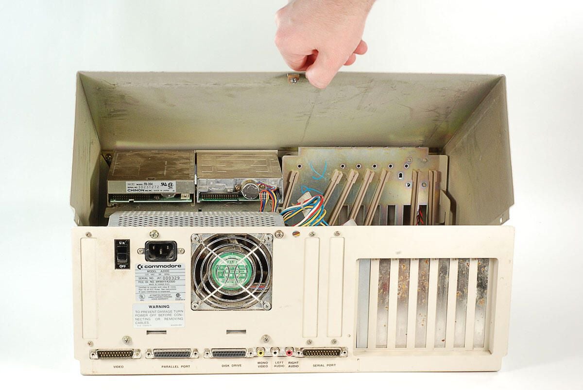
\n\tAfter removing all the external case screws, you can lift the top of the metal case away from the Amiga 2000.
\n
\n\tPhoto by: Bill Detwiler / TechRepublic
\n\tCaption by: Bill Detwiler
\n\tWith the top half of the case and attached front cover removed, we can see this machines two 3.5″ disk drives and the plastic housing for the Power and Hard Drive activity lights.
\n
\n\tPhoto by: Bill Detwiler / TechRepublic
\n\tCaption by: Bill Detwiler
\n\tThere is a lot of dust inside this Amiga 2000’s case.
\n
\n\tPhoto by: Bill Detwiler / TechRepublic
\n\tCaption by: Bill Detwiler
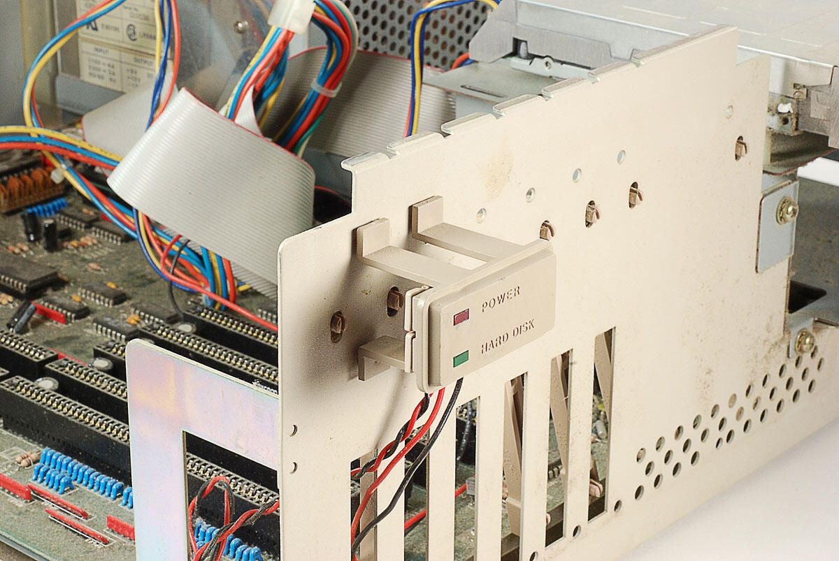
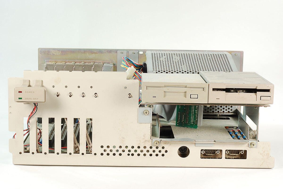
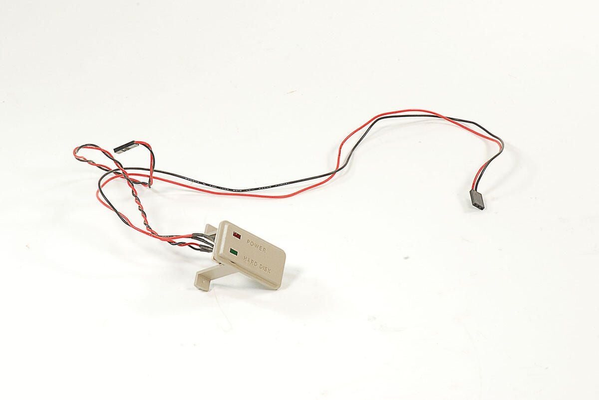
\n\tThe Amiga 2000’s Power and Hard Disk activity lights are mounted on a plastic stand that sticks out from the internal metal case. Despite the presence of a Hard Disk activity light, this machine did not come with an internal hard drive.
\n
\n\tPhoto by: Bill Detwiler / TechRepublic
\n\tCaption by: Bill Detwiler
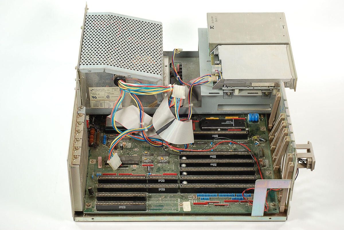
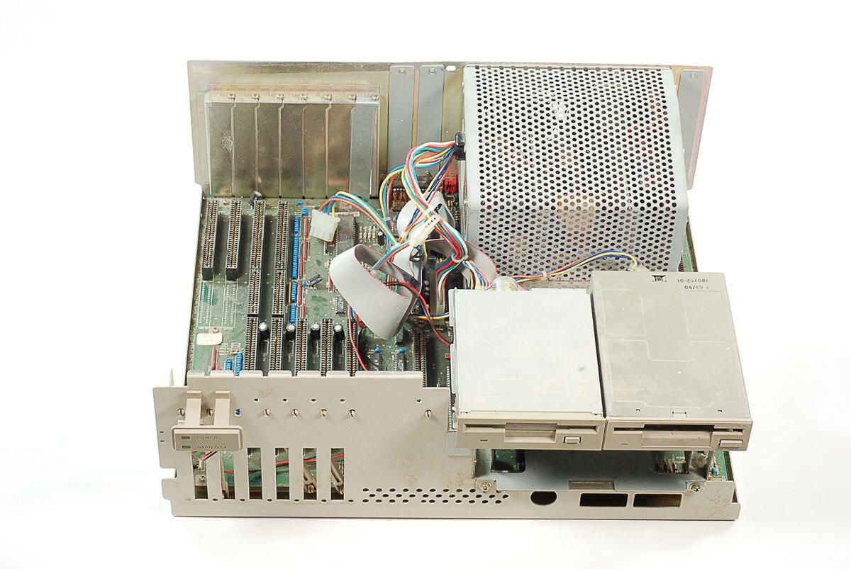
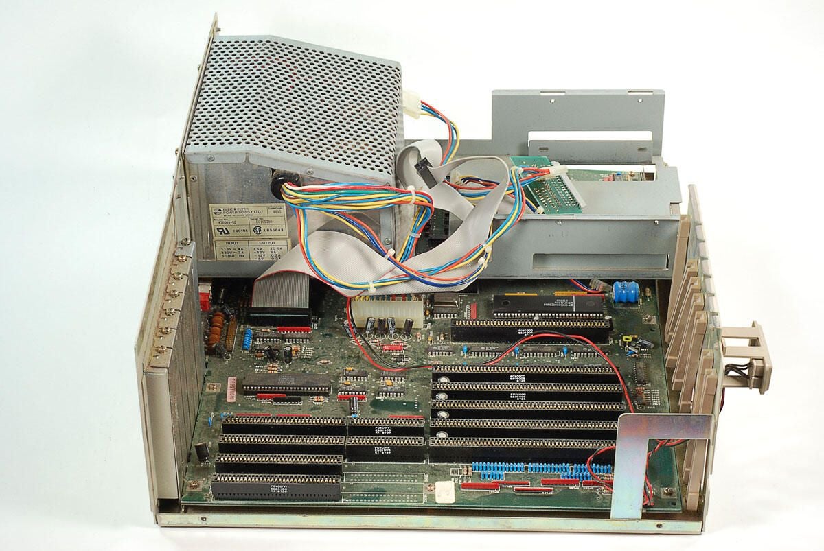
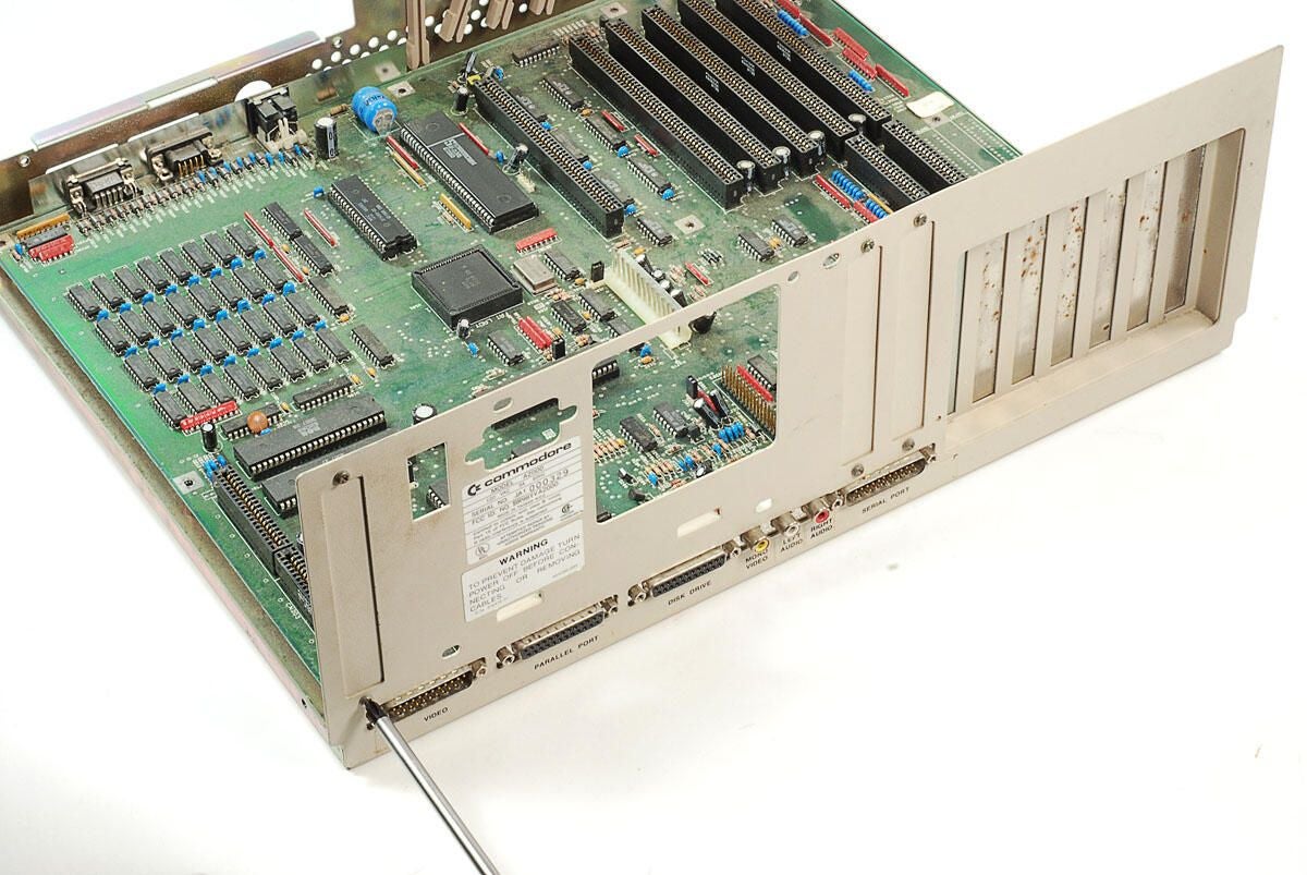
\n\tLooking at the Amiga 2000 from the side, we can see part of the motherboard. Some of the board is covered with a large metal frame, which holds the power supply unit, two 3.5″ drives, and 5.25″ drive (if one was present).
\n
\n\tPhoto by: Bill Detwiler / TechRepublic
\n\tCaption by: Bill Detwiler
\n\tMore dust has accumulated on the motherboard.
\n
\n\tPhoto by: Bill Detwiler / TechRepublic
\n\tCaption by: Bill Detwiler
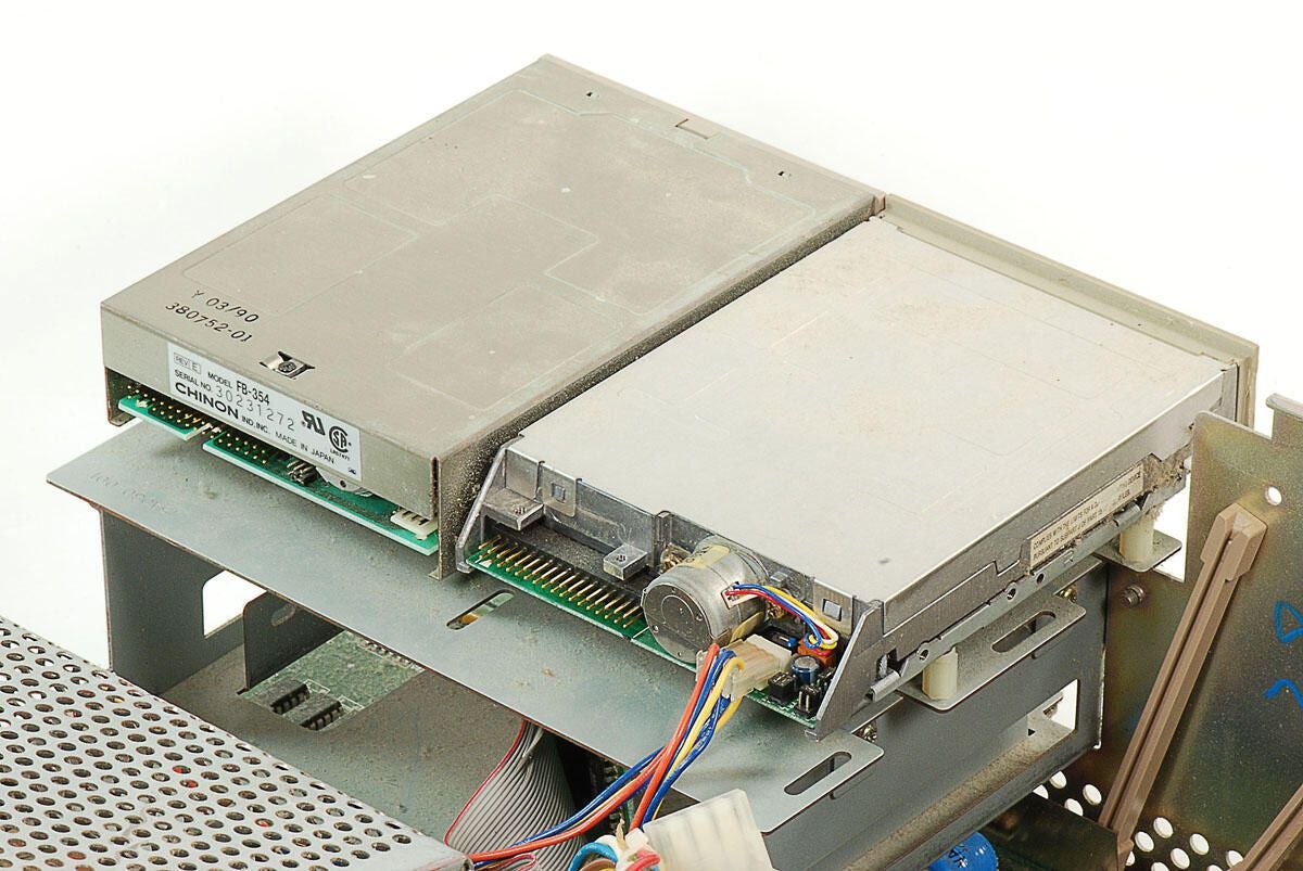
\n\tThis Amiga 2000 definitely wouldn’t have worked in this condition. It seems that a previous owner disconnected most of the 3.5″ disk drive cables before shipping the machine.
\n
\n\tPhoto by: Bill Detwiler / TechRepublic
\n\tCaption by: Bill Detwiler
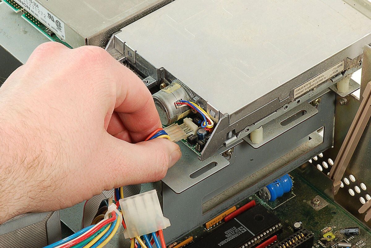
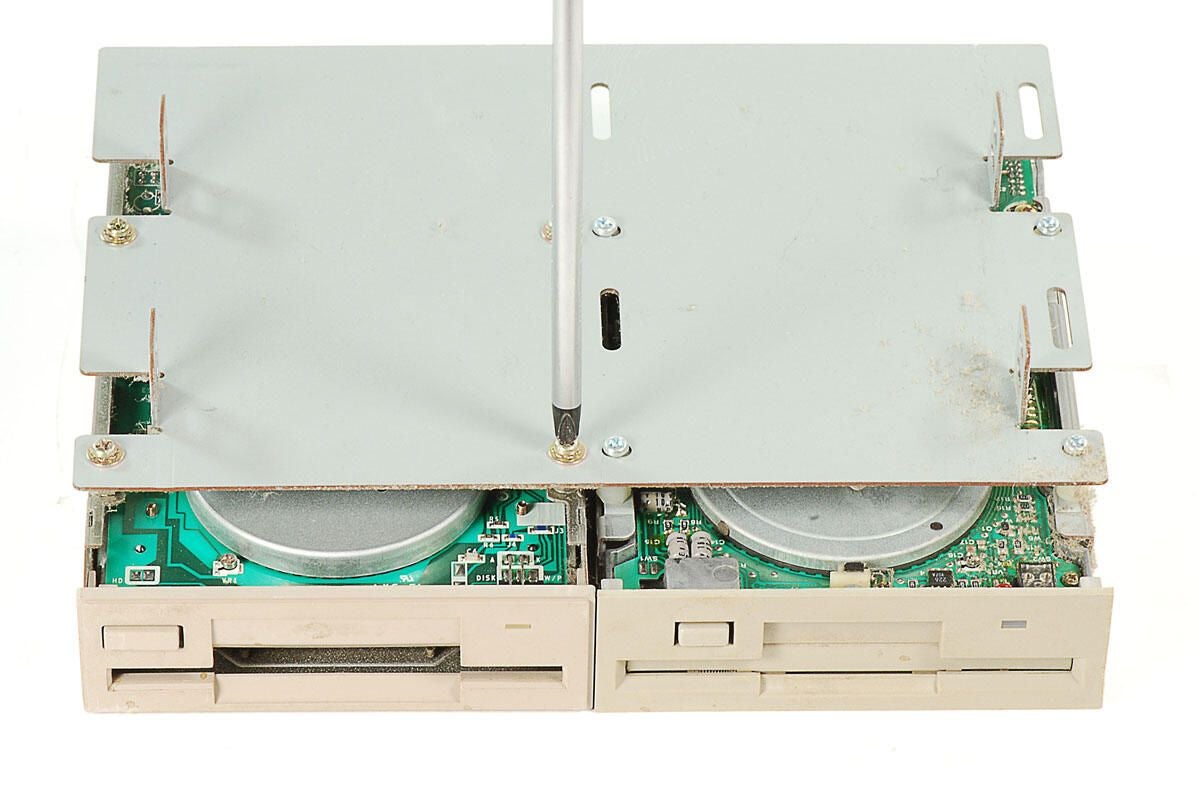
\n\tBefore removing the 3.5″ disk drives, we’ll need to disconnect that power and data cables. As I noted on the previous photo, someone had already detached most of the drive cables. I’ll remove the lone power cable that remained attached.
\n
\n\tPhoto by: Bill Detwiler / TechRepublic
\n\tCaption by: Bill Detwiler
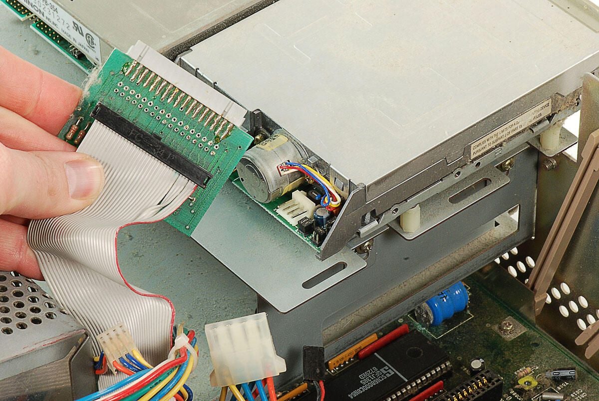
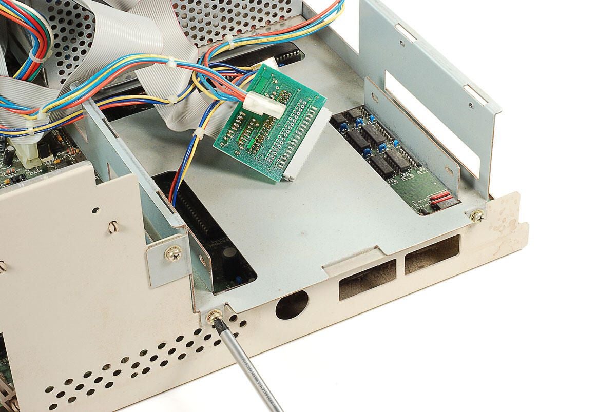
\n\tA small circuit board is attached to the end of the ribbon cable. Neither of this cable’s connectors were attached to the 3.5″ drives.
\n
\n\tPhoto by: Bill Detwiler / TechRepublic
\n\tCaption by: Bill Detwiler
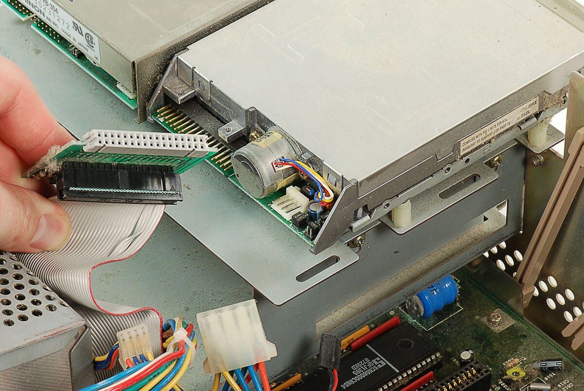
\n\tThe both the ribbon cable and the small circuit board have 34-pin female connectors–matching the 34-pin male connectors on the two 3.5″ drives. I’m not 100 percent sure of the the circuit board’s function, but it could simply facilitate the connection of drives when mounted next to each other–instead of on top of each other.
\n
\n\tPhoto by: Bill Detwiler / TechRepublic
\n\tCaption by: Bill Detwiler
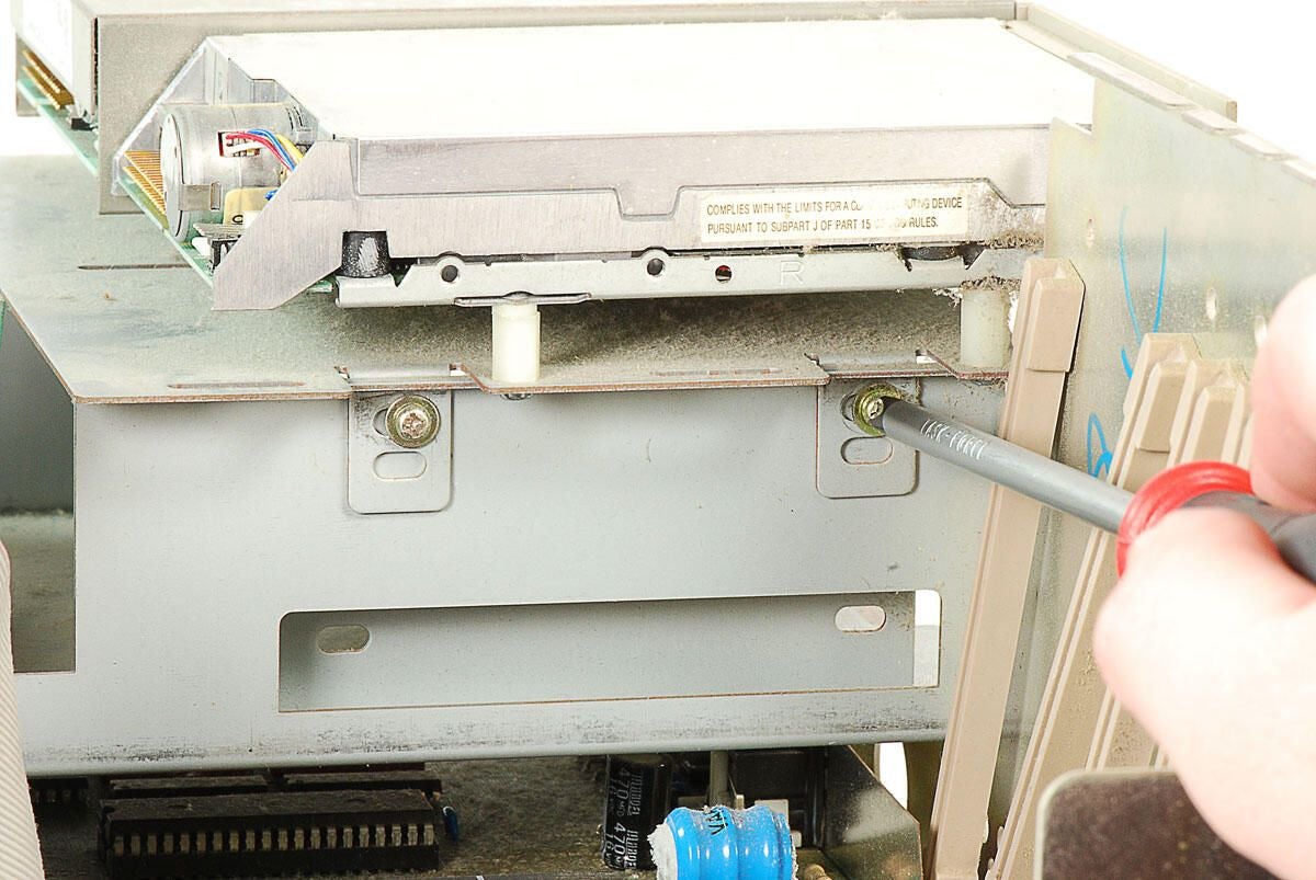
\n\tWith all the cables disconnected, we can remove the metal plate holding the Amiga 2000’s two 3.5″ drives. Four screws (two on each side) hold the disk drive mounting plate to the internal metal frame.
\n
\n\tPhoto by: Bill Detwiler / TechRepublic
\n\tCaption by: Bill Detwiler
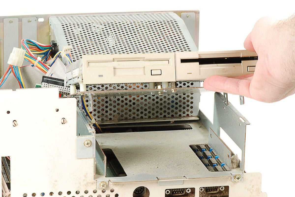
\n\tWith all four screws removed, we can lift the mounting plate, and attached drives, away from the Amiga 2000’s internal metal frame.
\n
\n\tPhoto by: Bill Detwiler / TechRepublic
\n\tCaption by: Bill Detwiler
\n\tPhoto by: Bill Detwiler / TechRepublic
\n\tCaption by: Bill Detwiler
\n\tPhoto by: Bill Detwiler / TechRepublic
\n\tCaption by: Bill Detwiler
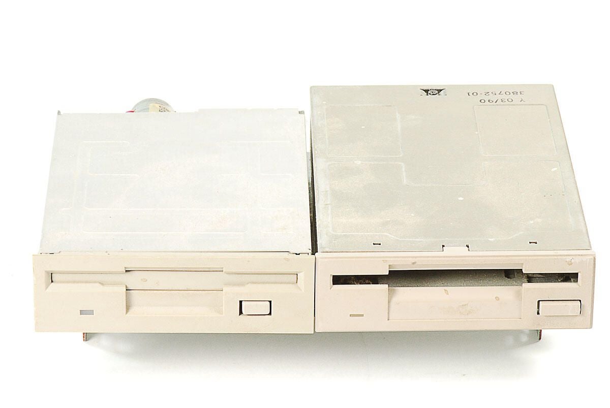
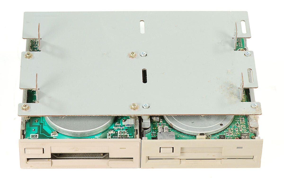
\n\tFour screws hold each of the Amiage 2000’s 3.5″ drives to the mounting plate.
\n
\n\tPhoto by: Bill Detwiler / TechRepublic
\n\tCaption by: Bill Detwiler
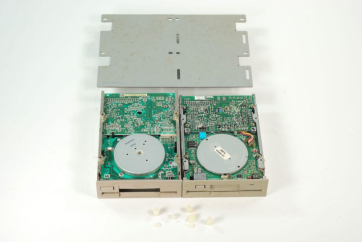
\n\tWith the screws removed, the Amiga 2000’s 3.5″ drives can be separated from the mounting plate. Small plastic spacers were used on the thinner drive (right).
\n
\n\tPhoto by: Bill Detwiler / TechRepublic
\n\tCaption by: Bill Detwiler
\n\tPhoto by: Bill Detwiler / TechRepublic
\n\tCaption by: Bill Detwiler
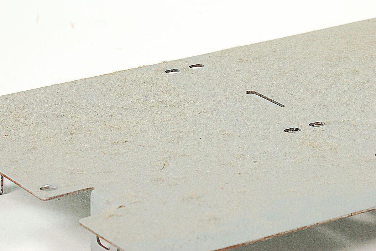
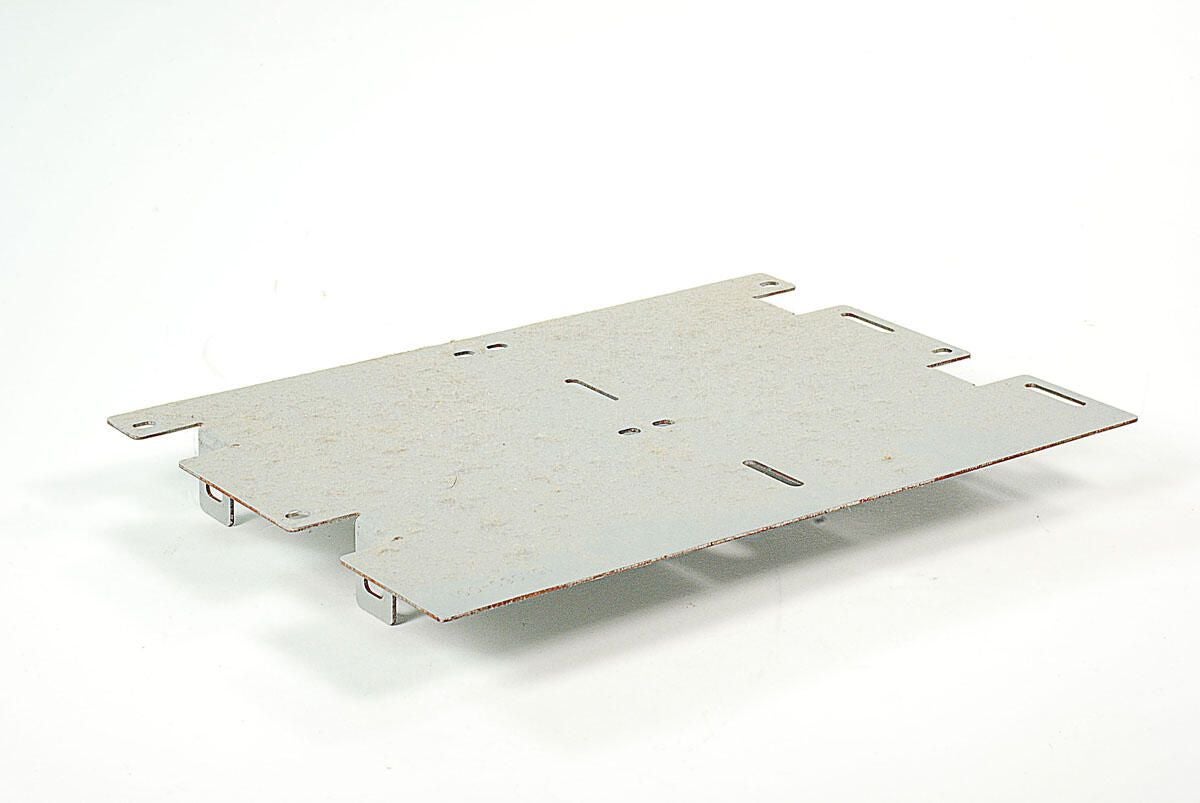
\n\tLike the other internal surfaces on this Amiga 2000, the 3.5″ drive mounting plate is covered with dust.
\n
\n\tPhoto by: Bill Detwiler / TechRepublic
\n\tCaption by: Bill Detwiler
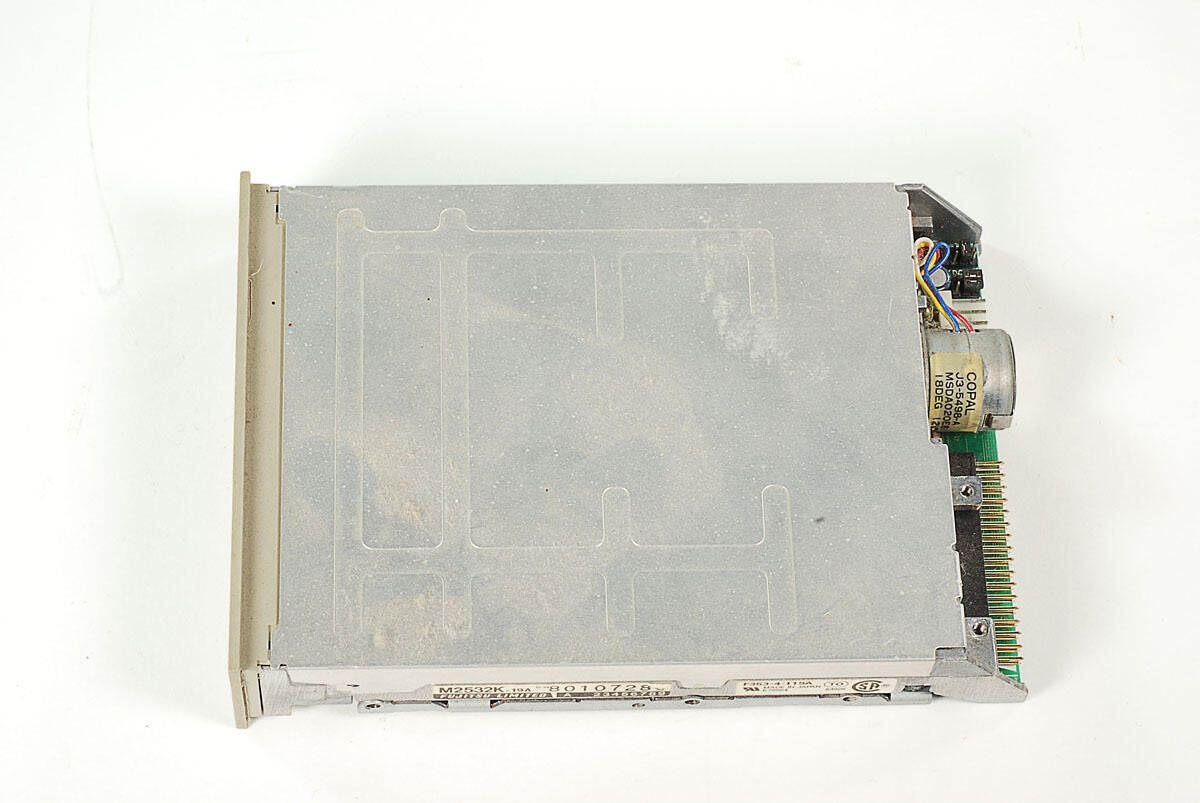
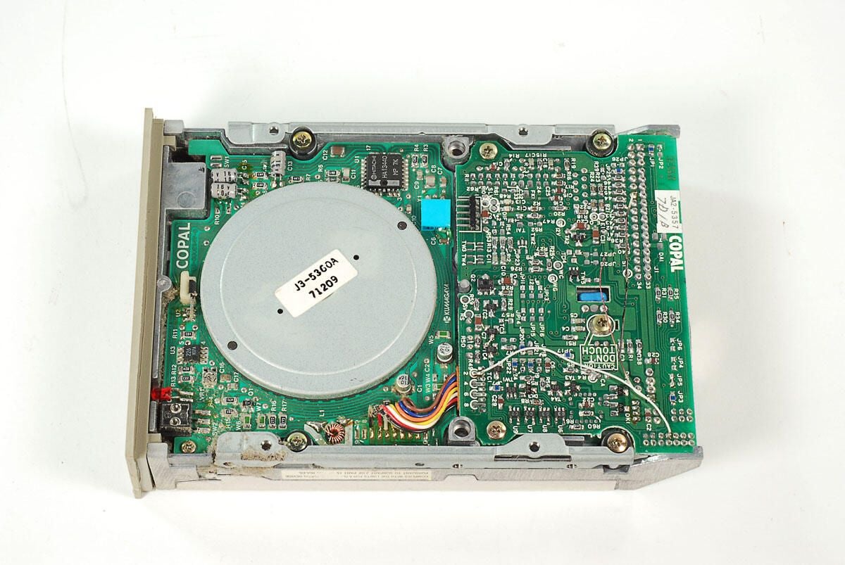
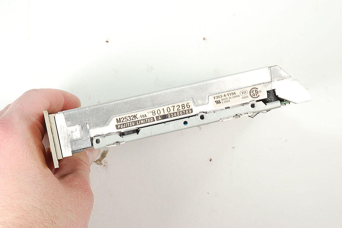
\n\tOne of the 3.5″ disk drives in this Amiga 2000 was a Fujitsu M2532K-19A.
\n
\n\tPhoto by: Bill Detwiler / TechRepublic
\n\tCaption by: Bill Detwiler
\n\tPhoto by: Bill Detwiler / TechRepublic
\n\tCaption by: Bill Detwiler
\n\tPhoto by: Bill Detwiler / TechRepublic
\n\tCaption by: Bill Detwiler
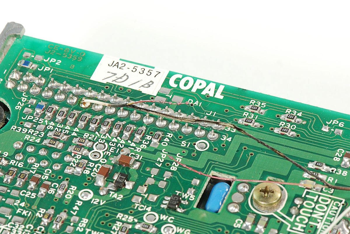
\n\tEven if I had connected all the cables and powered on this Amiga 2000, I doubt its Fujitsu M2532K-19A drive would have worked. A thin wire soldered to the underside of the drive appears to have melted and torn. Note the charred shielding and broken wire.
\n
\n\tPhoto by: Bill Detwiler / TechRepublic
\n\tCaption by: Bill Detwiler
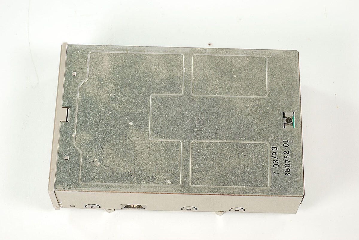
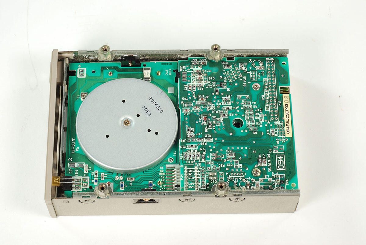
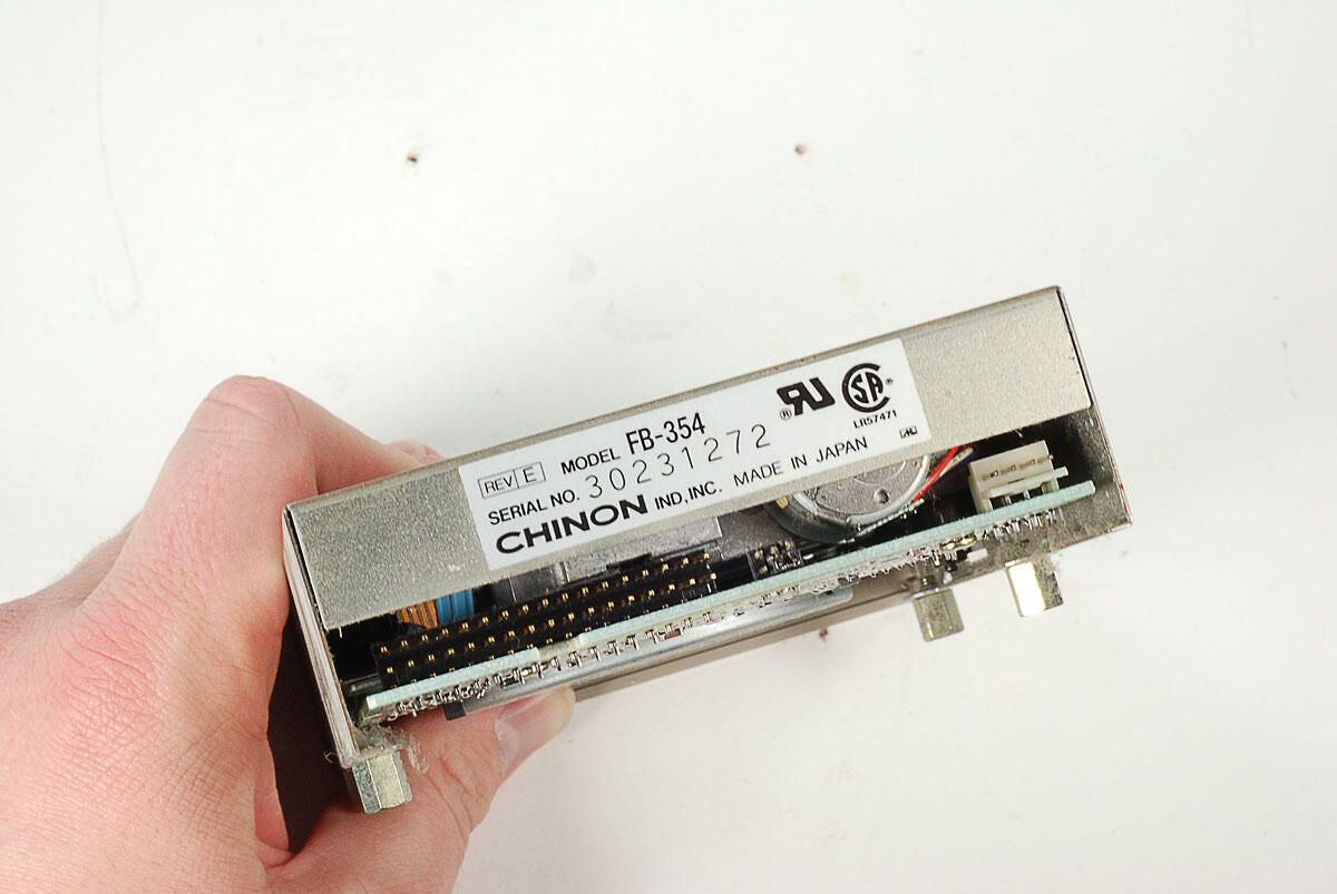
\n\tThe second 3.5″ disk drive in this Amiga 2000 was a Chinon FB-35A. Although the company dabbled in computer compents and peripherals, Chinon was best known in Japan as a camera manufacturer.
\n
\n\tPhoto by: Bill Detwiler / TechRepublic
\n\tCaption by: Bill Detwiler
\n\tPhoto by: Bill Detwiler / TechRepublic
\n\tCaption by: Bill Detwiler
\n\tPhoto by: Bill Detwiler / TechRepublic
\n\tCaption by: Bill Detwiler
\n\tWith the 3.5″ drives and mounting plate removed, we’ll turn our attention to the large, internal metal frame, which also holds the power supply.
\n
\n\tPhoto by: Bill Detwiler / TechRepublic
\n\tCaption by: Bill Detwiler
\n\tThree screws hold the front of the metal frame to the lower half of the Amiga 2000’s metal case.
\n
\n\tPhoto by: Bill Detwiler / TechRepublic
\n\tCaption by: Bill Detwiler
\n\tFour screws hold the back of internal metal frame to the lower half of the Amiga 2000’s metal case.
\n
\n\tPhoto by: Bill Detwiler / TechRepublic
\n\tCaption by: Bill Detwiler
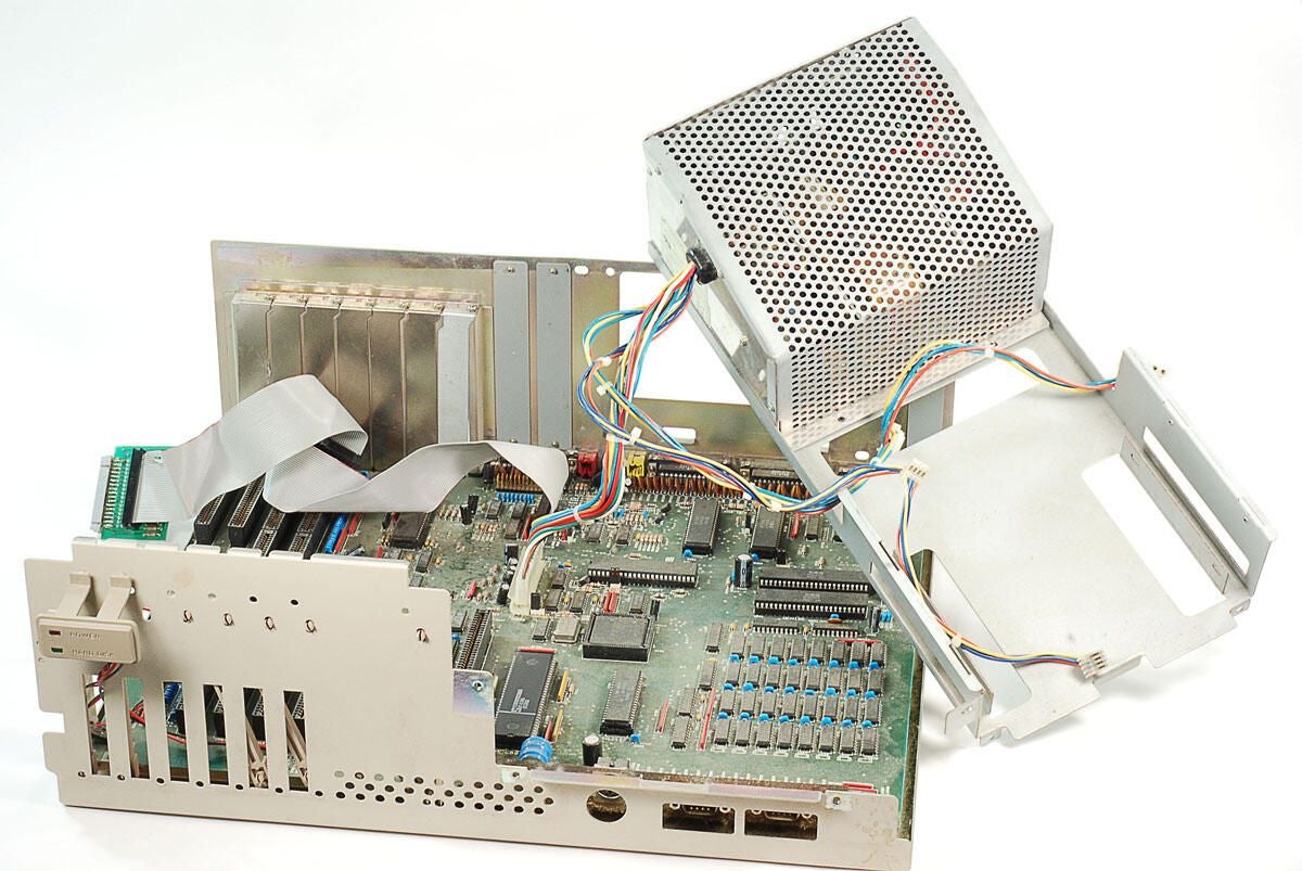
\n\tWith the seven screws removed, you can lift the internal metal frame away from the Amiga 2000’s case. Before we can completely separated the frame of the case, we’ll need to disconnect the motherboard’s power cable.
\n
\n\tPhoto by: Bill Detwiler / TechRepublic
\n\tCaption by: Bill Detwiler
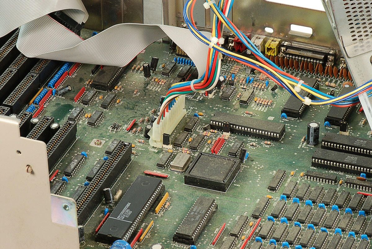
\n\tYou’ll need to disconnect the motherboard’s power cable before completely removing the Amiga 2000’s internal metal frame and attached power supply.
\n
\n\tPhoto by: Bill Detwiler / TechRepublic
\n\tCaption by: Bill Detwiler
\n\tPhoto by: Bill Detwiler / TechRepublic
\n\tCaption by: Bill Detwiler
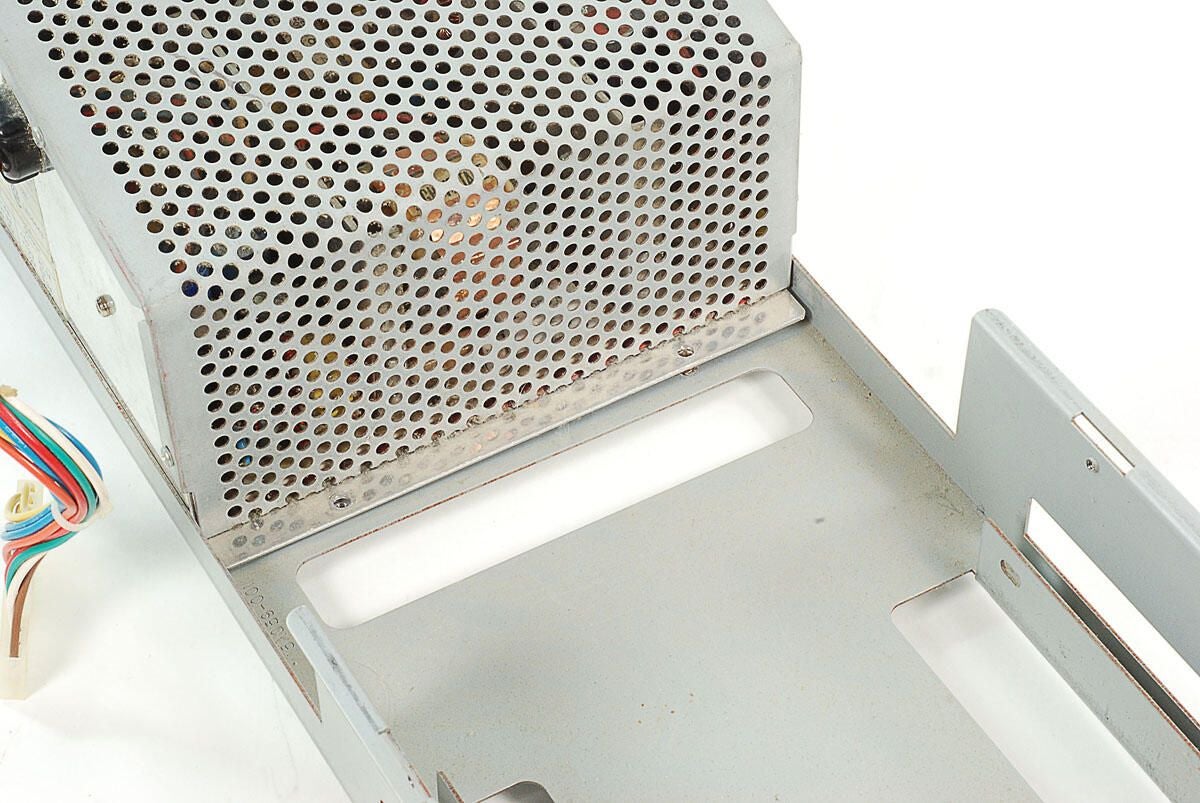
\n\tTwo screws should hold the Amiga 2000’s power supply securely to the internal metal frame, but one of the screws in missing and the other is connected only to the frame and not the power supply.
\n
\n\tPhoto by: Bill Detwiler / TechRepublic
\n\tCaption by: Bill Detwiler
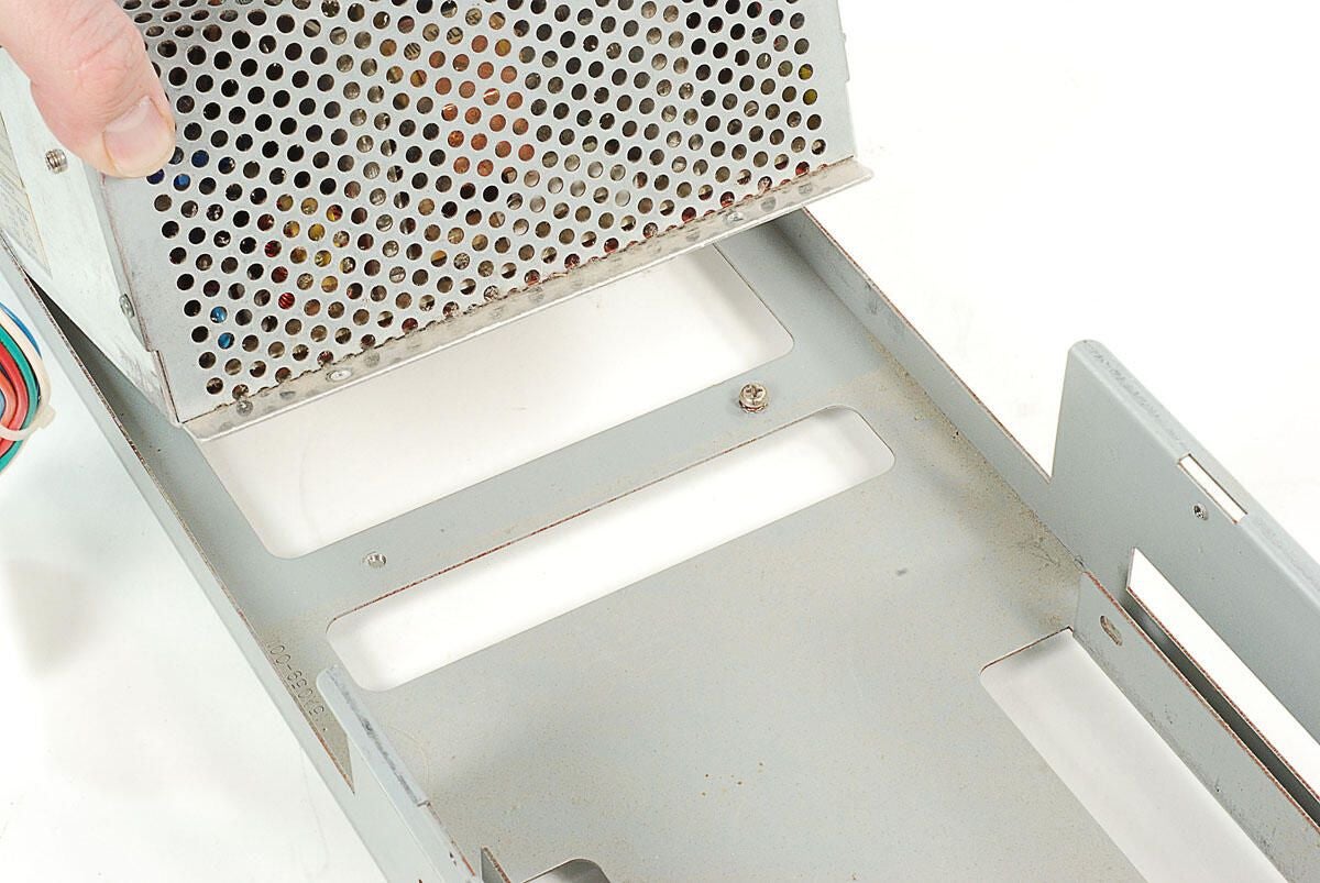
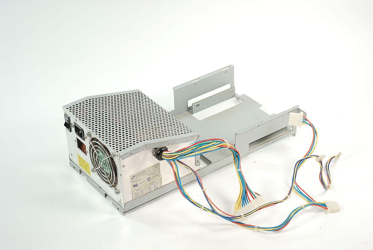
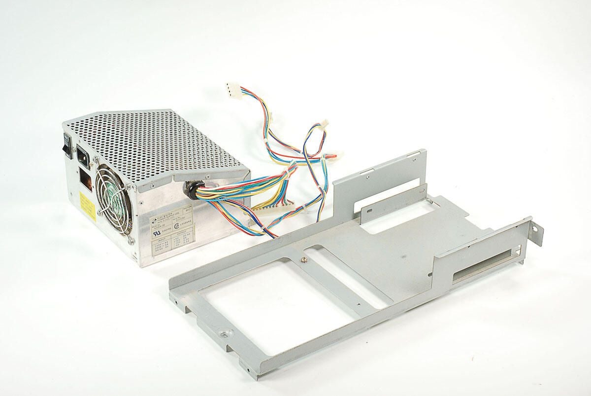
\n\tAs no screws are holding the Amiga 2000’s power supply to the internal frame, we can lift the supply away from the frame.
\n
\n\tPhoto by: Bill Detwiler / TechRepublic
\n\tCaption by: Bill Detwiler
\n\tPhoto by: Bill Detwiler / TechRepublic
\n\tCaption by: Bill Detwiler
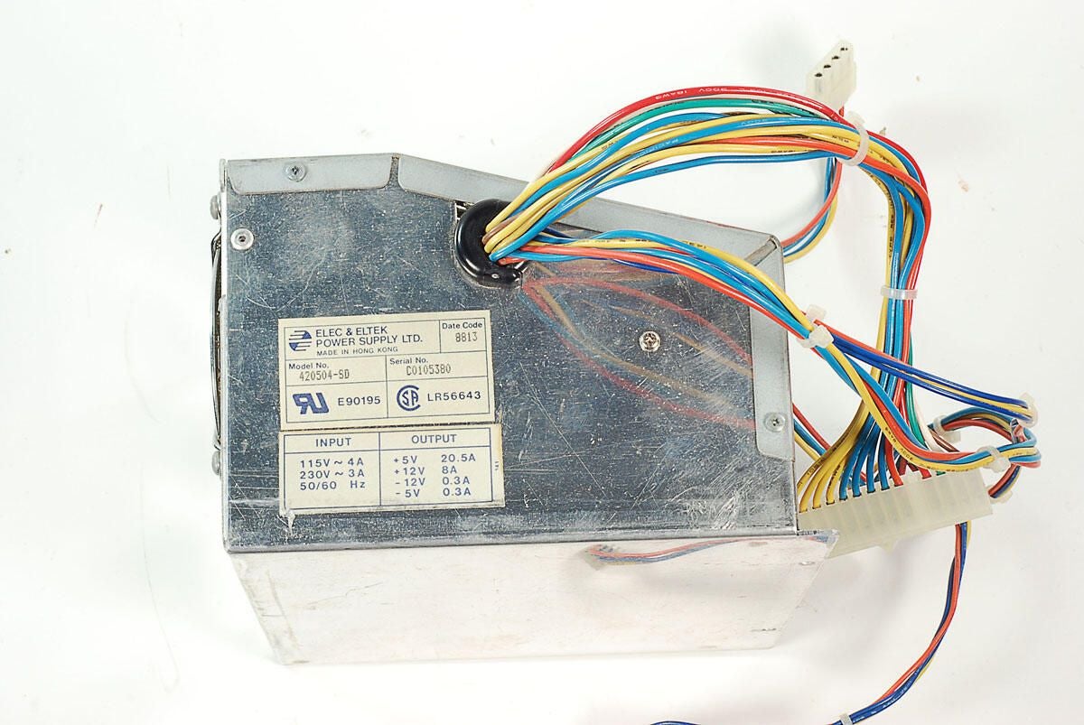
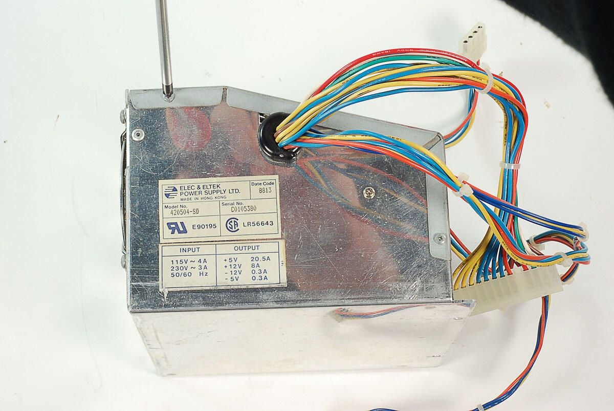
\n\tThis Amiga 2000 has an Elec & Eltek 420504-SD power supply.
\n
\n\tPhoto by: Bill Detwiler / TechRepublic
\n\tCaption by: Bill Detwiler
\n\tWhile I normally recommend you don’t crack open PC power supplies, I’m going to carefully remove this supply’s cover
\n
\n\tWarning: Computer power supply units (PSUs) contain components that can deliver dangerous electric shocks. The capcitors inside most PSUs can retain an electrical charge for a long time after being removed from a power source. You should never open or work on a PSU without proper training.
\n
\n\tPhoto by: Bill Detwiler / TechRepublic
\n\tCaption by: Bill Detwiler
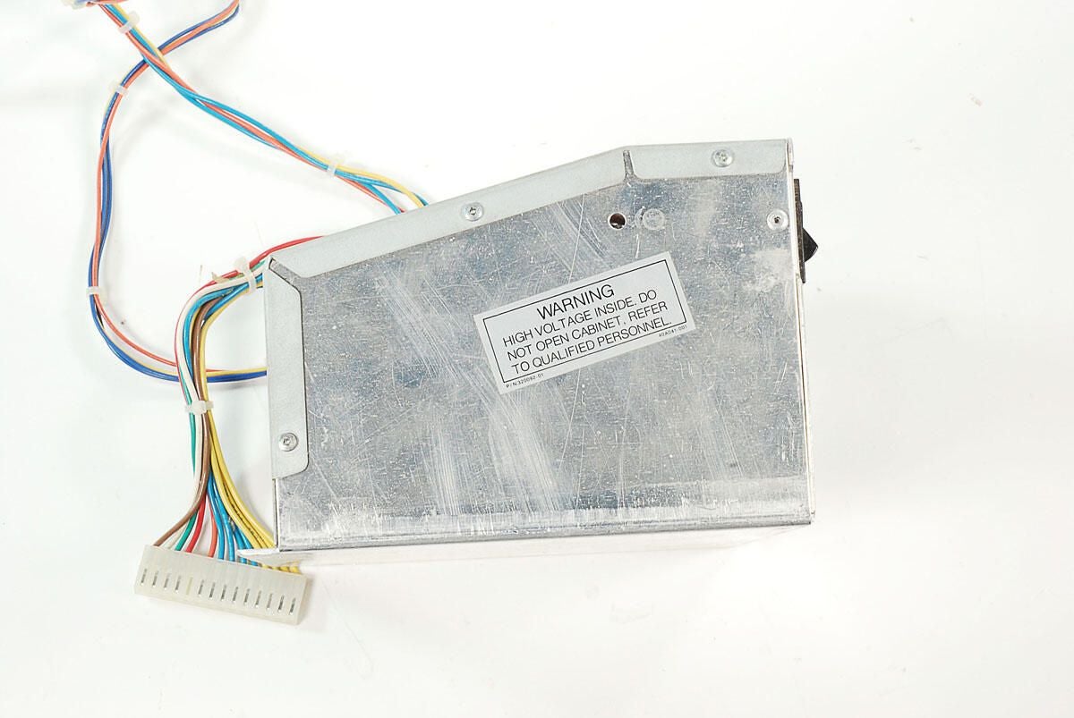
\n\tNote the warning label of the other side of the Amiga 2000’s power supply unit.
\n
\n\tPhoto by: Bill Detwiler / TechRepublic
\n\tCaption by: Bill Detwiler
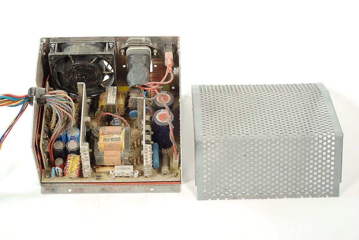
\n\tWith the cover removed, we get our first look inside the Amiga 2000’s power supply unit. Remember, look but don’t touch!
\n
\n\tPhoto by: Bill Detwiler / TechRepublic
\n\tCaption by: Bill Detwiler
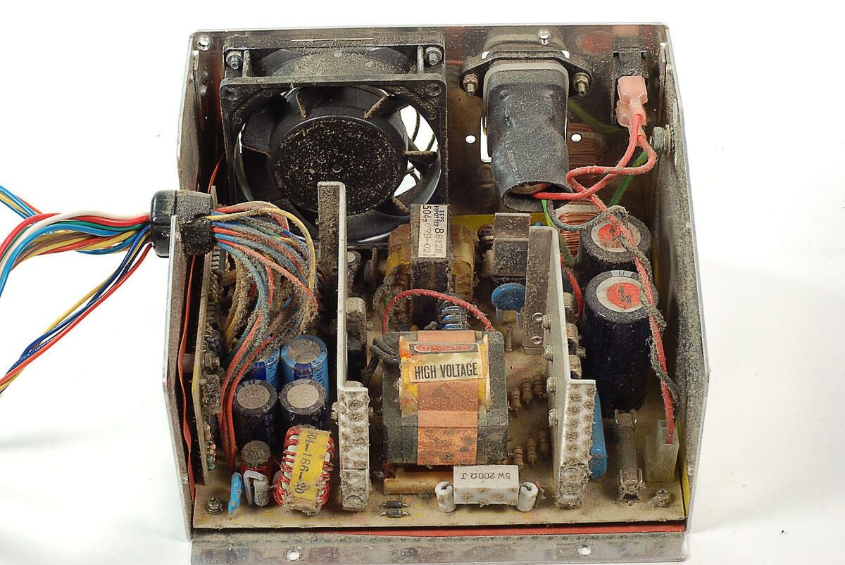
\n\tWow. There’s a lot of dust and grime inside this Amiga 2000’s power supply unit. I will not be cleaning, or even touching these components.
\n
\n\tPhoto by: Bill Detwiler / TechRepublic
\n\tCaption by: Bill Detwiler
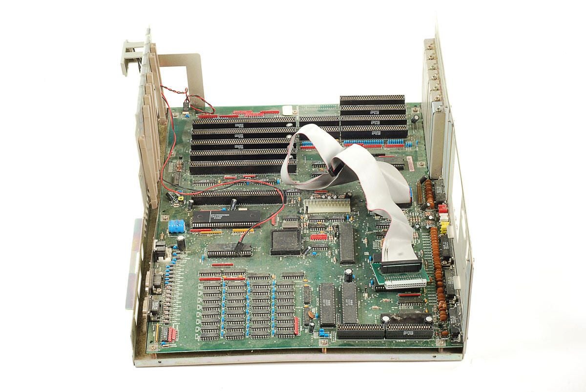
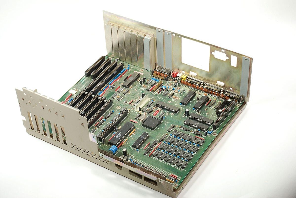
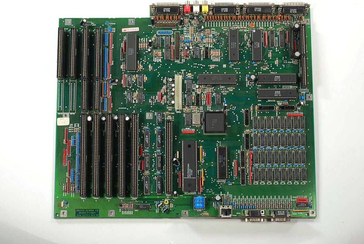
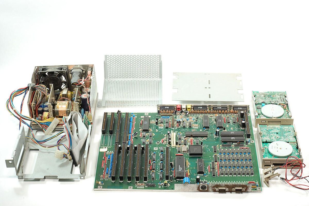
\n\tWith the internal metal frame and attached components removed, we can finally see the entire Amiga 2000’s motherboard.
\n
\n\tPhoto by: Bill Detwiler / TechRepublic
\n\tCaption by: Bill Detwiler
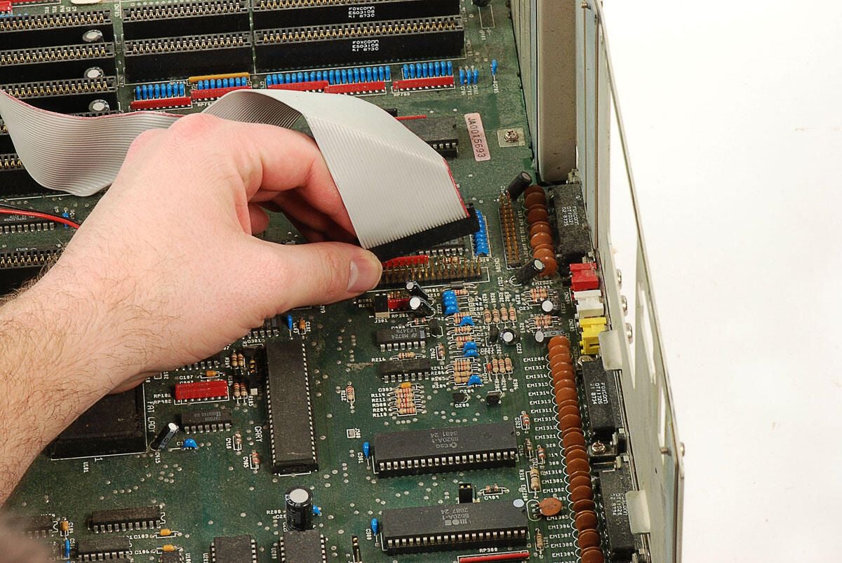
\n\tBefore removing the motherboard from the lower half of the Amiga 2000’s case, we’ll need to disconnect the ribbon cable for the two 3.5″ disk drives.
\n
\n\tPhoto by: Bill Detwiler / TechRepublic
\n\tCaption by: Bill Detwiler
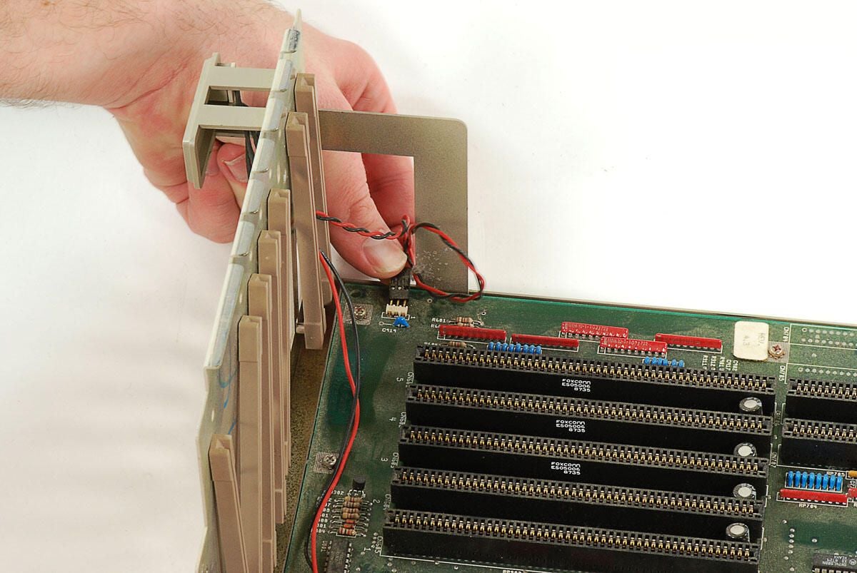
\n\tWe’ll also need to disconnect the cable for the Amiga 2000’s Power light. Although this Amiga 2000 has a Hard Disk activity light, it did not come with a hard drive. A SCSI hard drive was available on A2000HD systems.
\n
\n\tPhoto by: Bill Detwiler / TechRepublic
\n\tCaption by: Bill Detwiler
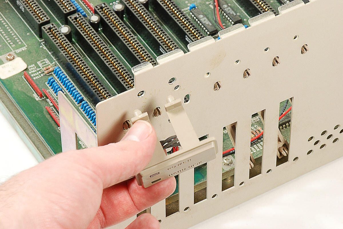
\n\tWith the Power and Hard Disk activity light cable disconnected, you can pop the plastic stand off the lower half of the Amiga 2000’s metal case.
\n
\n\tPhoto by: Bill Detwiler / TechRepublic
\n\tCaption by: Bill Detwiler
\n\tPhoto by: Bill Detwiler / TechRepublic
\n\tCaption by: Bill Detwiler
\n\tWith the internal metal frame, drives, power supply, and cables removed, we can begin removing the Amiga 200’s motherboard from the lower half of the case.
\n
\n\tPhoto by: Bill Detwiler / TechRepublic
\n\tCaption by: Bill Detwiler
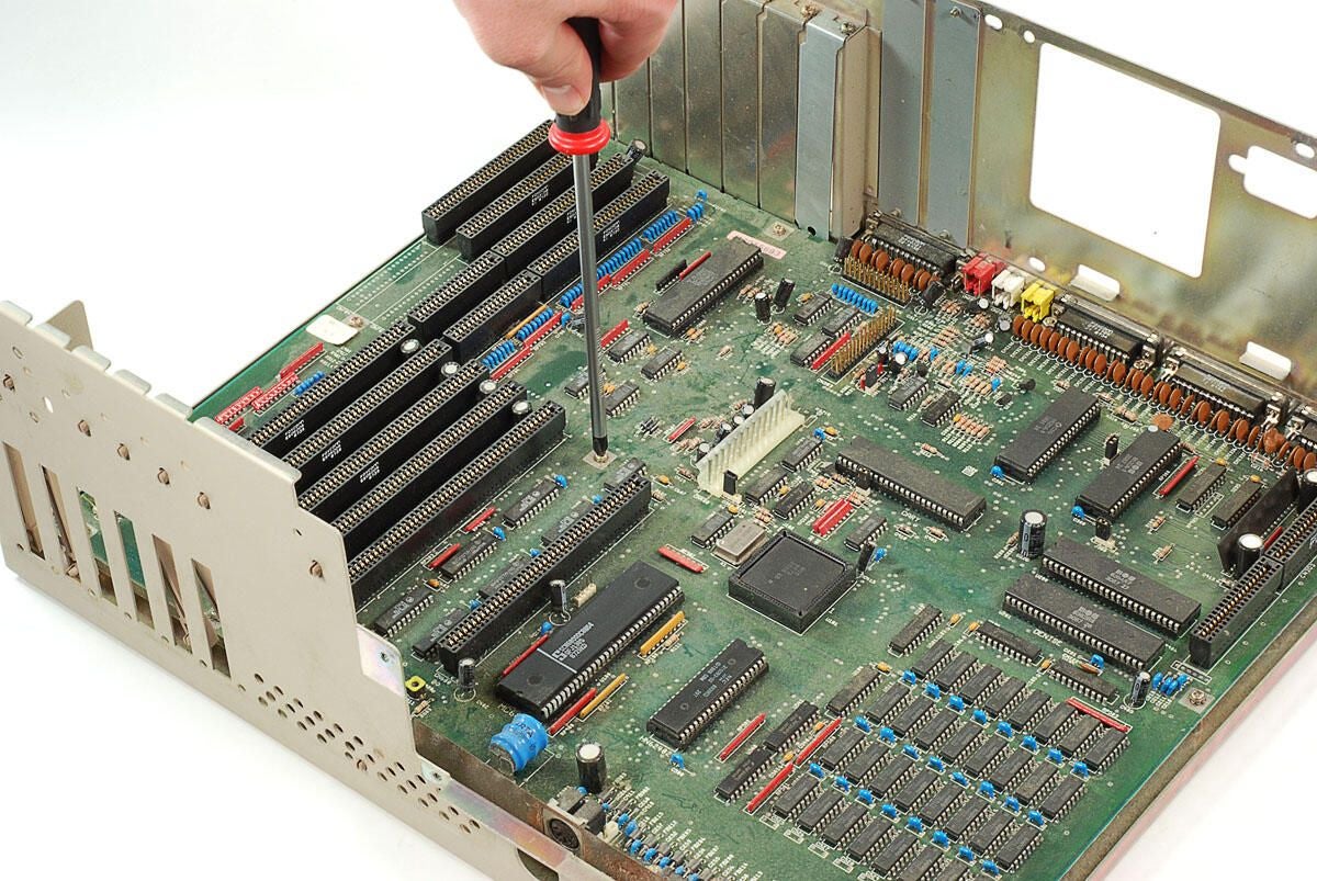
\n\tSeveral screws hold the Amiga 2000’s motherboard and attached plate to the lower half of the case.
\n
\n\tPhoto by: Bill Detwiler / TechRepublic
\n\tCaption by: Bill Detwiler
\n\tOnce you’ve removed all the screws holding the the motherboard to the case, you’ll also need to remove the bottom screws from the expansion slot covers above the rear ports. These metal covers slightly overlap the metal shield that surrounds the rear ports. You don’t actually need to remove the three covers, just remove the lower screw and then swing the covers up enough to slide out the motherboard and attached metal plate.
\n
\n\tPhoto by: Bill Detwiler / TechRepublic
\n\tCaption by: Bill Detwiler
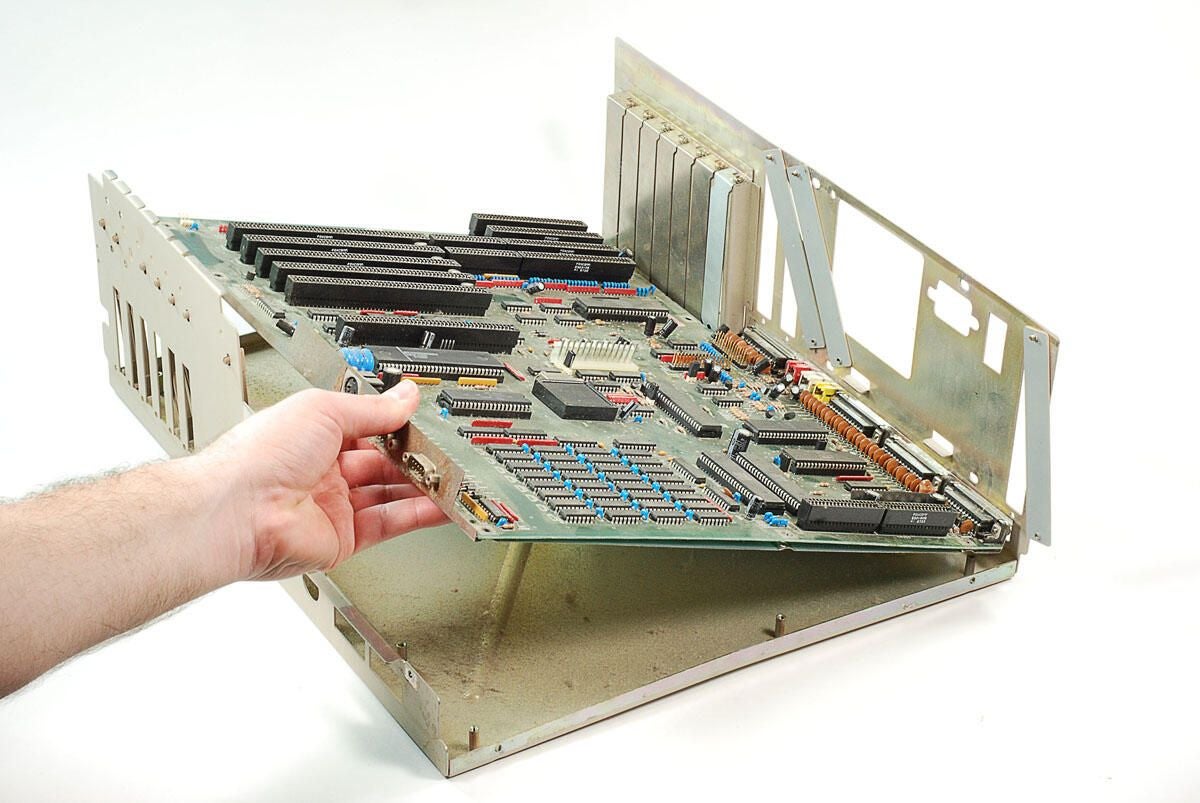
\n\tOnce you’ve removed motherboard screws and pushed aside the expansion slot covers, you can lift the motherboard away from the Amiga 2000’s case.
\n
\n\tPhoto by: Bill Detwiler / TechRepublic
\n\tCaption by: Bill Detwiler
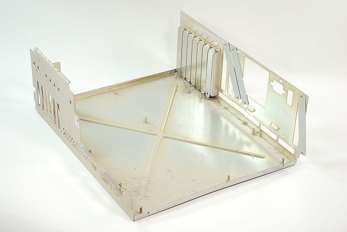
\n\tWith the motherboard removed, there’s nothing left inside the lower half of the Amiga 2000’s case.
\n
\n\tPhoto by: Bill Detwiler / TechRepublic
\n\tCaption by: Bill Detwiler
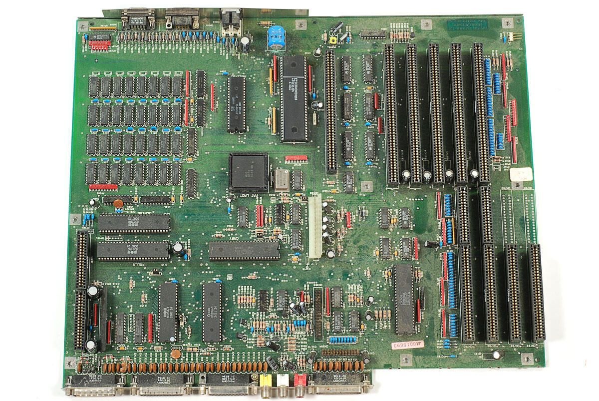
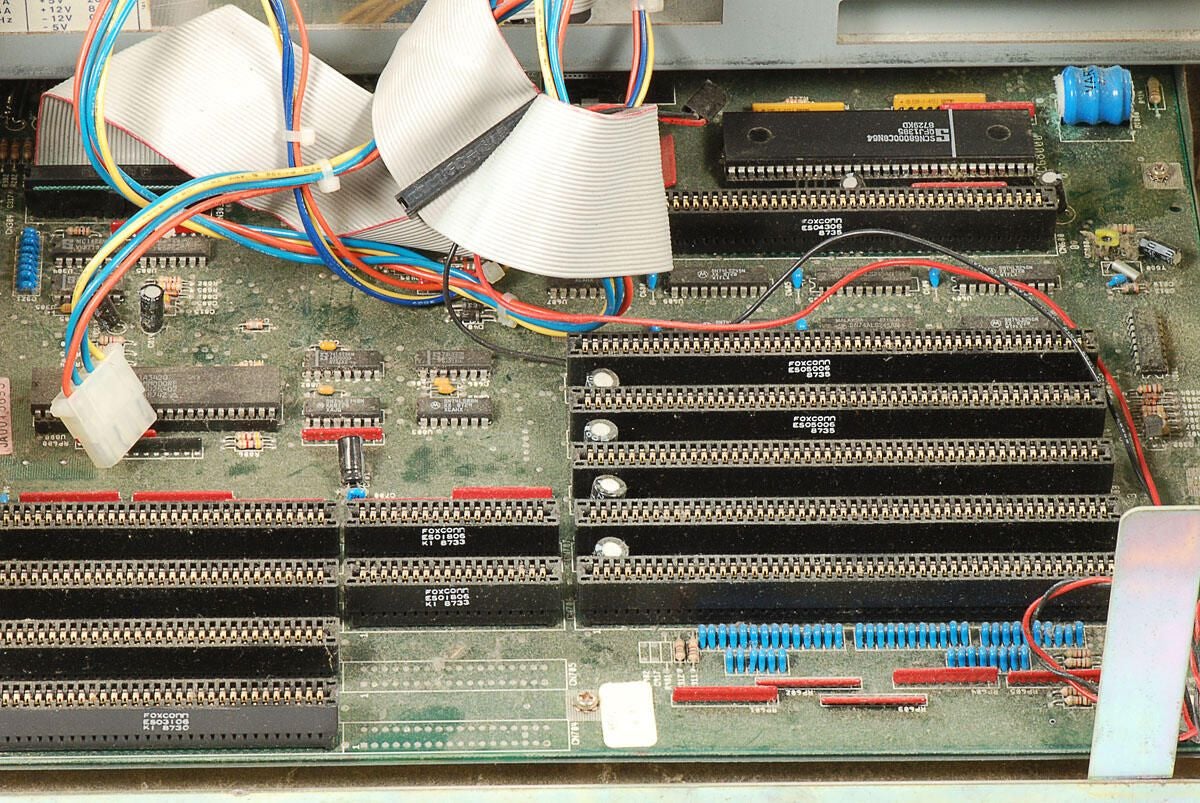
\n\tThis Amiga 2000 (B2000-CR) has five Zorro II (Amiga proprietary) slots, two 16-bit ISA slots, two 8-bit ISA slots, one video slot connector, and one 32-pin disk drive connector. The four ISA slots will only provide power to attached cards. The Amiga doesn’t have the ability to navtively communicate with these type of cards. However, using a Commodore bridgeboard the slot could be activated and used.
\n
\n\tAs with all the surfaces within this machine, the motherboard is covered with dust. Before taking any close-up shots of the chips, I’m going to spen a little time and effort cleaning off the dust.
\n
\n\tPhoto by: Bill Detwiler / TechRepublic
\n\tCaption by: Bill Detwiler
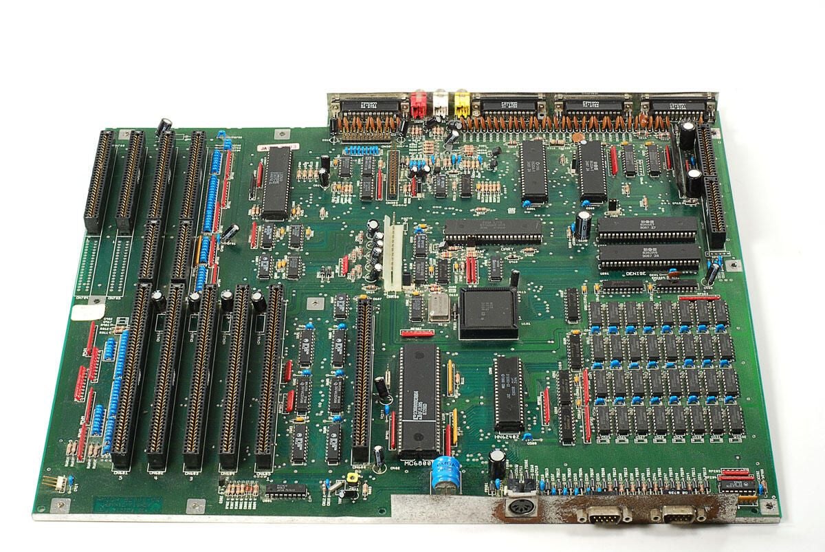
\n\tAfter 20 minutes of blowing and wiping away the dust, this Amiga 2000 motherboard looks much better.
\n
\n\tPhoto by: Bill Detwiler / TechRepublic
\n\tCaption by: Bill Detwiler
\n\tI’m going to leave the metal plate attached to the bottom of the motherboard. There’s really nothing put solder points under it.
\n
\n\tPhoto by: Bill Detwiler / TechRepublic
\n\tCaption by: Bill Detwiler
\n\tNow that we have cleaner motherboard, let’s take a look at the chips on this classic Amiga 2000.
\n
\n\tPhoto by: Bill Detwiler / TechRepublic
\n\tCaption by: Bill Detwiler
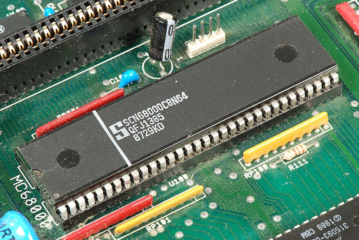
\n\tThe Amiga 2000 used a 7.16 MHz Motorola 68000 processor. In addition to Motorola, several companies also manufactured the chip. From this chip’s markings, I believe it is a 68000 microprocessor manufactured by Signetics. This chip has the markings:
\n
\n\tS
\n\tSCN68000C8N64
\n\tQFJ1385
\n\t8729KD
\n
\n\tPhoto by: Bill Detwiler / TechRepublic
\n\tCaption by: Bill Detwiler
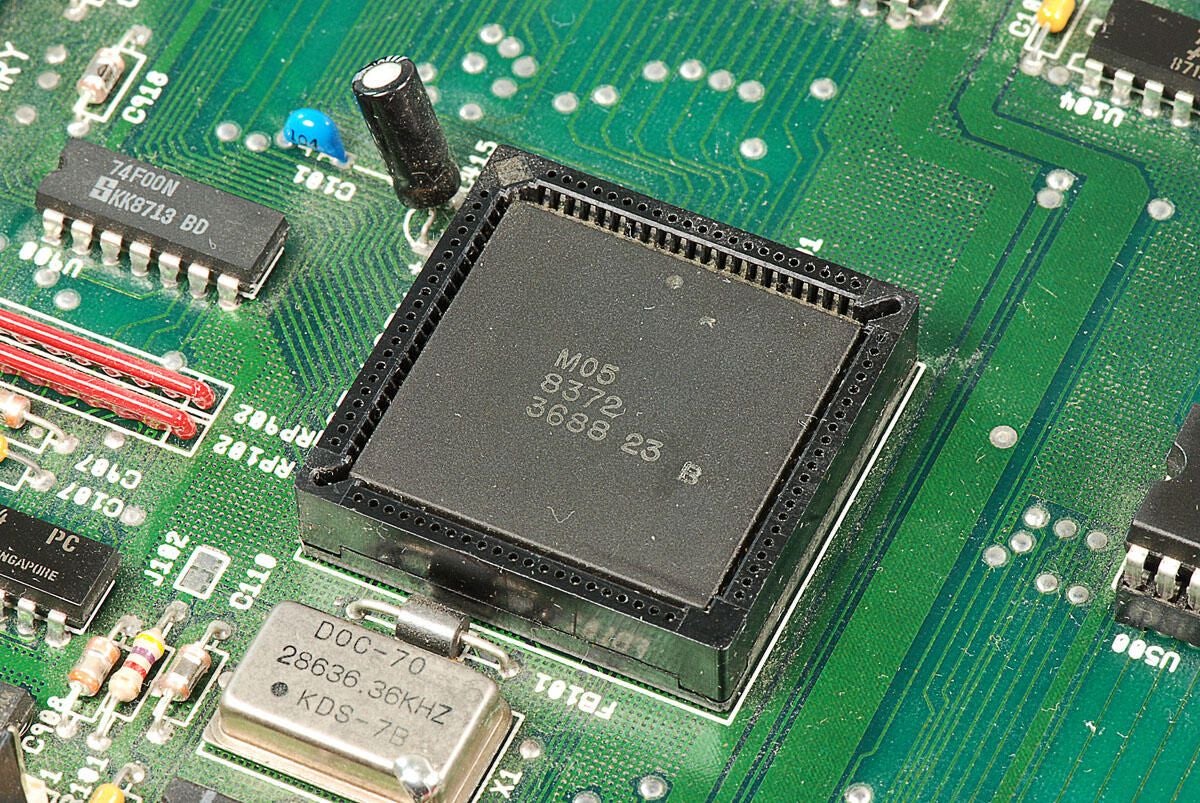
\n\tThis square chip is part of the MOS Technology “Angus” 8372 chipset. I’m not 100 percent certain, but I believe it is the address generator chip. It has the following markings:
\n
\n\tM05
\n\t8372
\n\t3688 23 B
\n
\n\tPhoto by: Bill Detwiler / TechRepublic
\n\tCaption by: Bill Detwiler
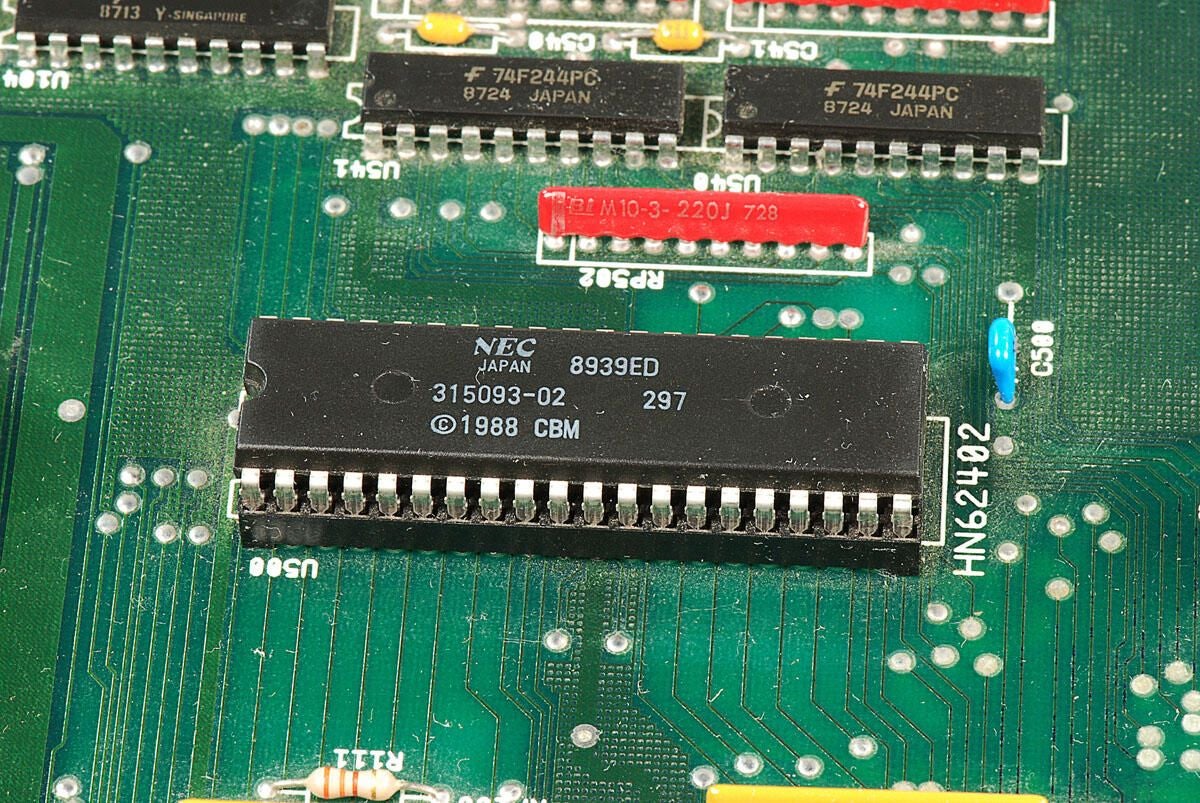
\n\tI believe this chip is the NEC 315093-02 256K ROM that contains the Amiga 2000’s Kickstart code. It has the markings:
\n
\n\tNEC
\n\tJapan 8939ED
\n\t315093-02 297
\n\t1988 CBM
\n
\n\tPhoto by: Bill Detwiler / TechRepublic
\n\tCaption by: Bill Detwiler
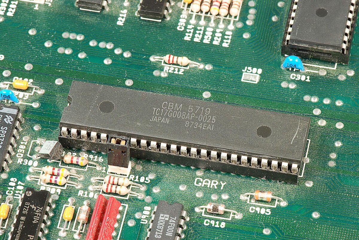
\n\tThis chip is the CBM (Commodore Business Machines) 5719 Gary Gate Array. It has the following markings:
\n
\n\tCBM 5719
\n\tTC17G008AP-0025
\n\tJAPAN 8734EAI
\n
\n\tPhoto by: Bill Detwiler / TechRepublic
\n\tCaption by: Bill Detwiler
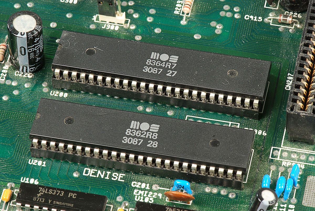
\n\tThese two chips are the MOS Technology 8362 (Denise Display Encoder) and MOS Technology 8364 (Paula Port Audio UART and Logic chip).
\n
\n\tThe have the markings:
\n
\n\tMOS
\n\t8364R7
\n\t3087 27
\n
\n\tMOS
\n\t8362R8
\n\t3087 28
\n
\n\tPhoto by: Bill Detwiler / TechRepublic
\n\tCaption by: Bill Detwiler
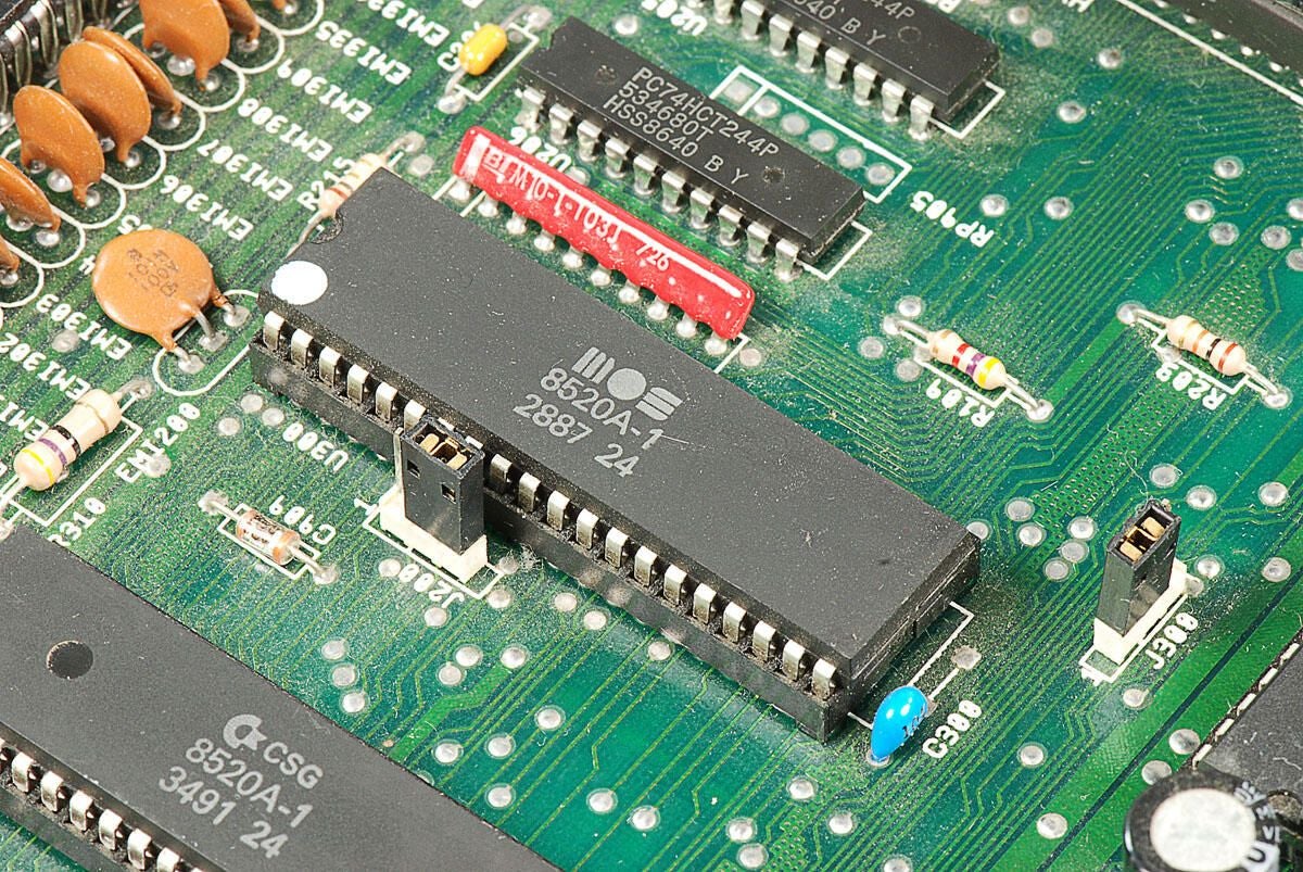
\n\tThis chip is the MOS 8520A-1 complex interface adapter. It has the following markings:
\n
\n\tMOS
\n\t8520A-1
\n\t2887 24
\n
\n\tPhoto by: Bill Detwiler / TechRepublic
\n\tCaption by: Bill Detwiler
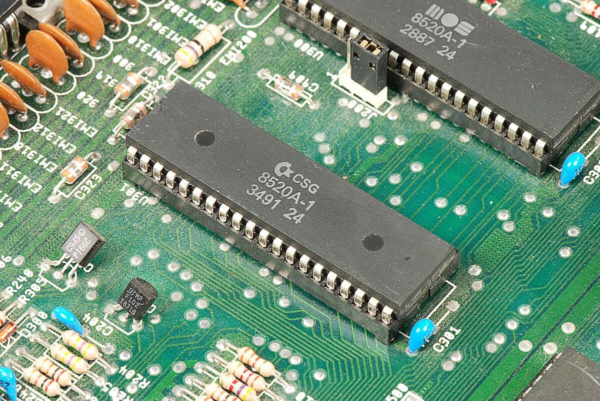
\n\tThis chip is the CSG 8520A-1 complex interface adapter. It has the following markings:
\n
\n\tCSG
\n\t8520A-1
\n\t3491 24
\n
\n\tPhoto by: Bill Detwiler / TechRepublic
\n\tCaption by: Bill Detwiler
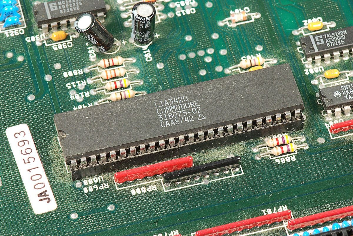
\n\tThis chip is the bus controller “Buster” 5721 Rev. A 318075-02. It has the following markings:
\n
\n\tL1A3420
\n\tCOMMODORE
\n\t318075-02
\n\tCAA8742
\n
\n\tEdited 1/8/2011: I orginally noted that this Buster chip was the “bus terminator”. Luckily, Dave Haynie jumped into this gallery’s discussion thread and set me straight. The Buster was the “bus controller” not the bus terminator.
\n
\n\tMr. Haynie was also kinda enough to supply a lot more great information about the Amiga 2000 and his work on the project. I can’t thank him enough for taking the time to do this.
\n
\n\tI encourage everyone to read through the discussion thread.
\n
\n\tPhoto by: Bill Detwiler / TechRepublic
\n\tCaption by: Bill Detwiler
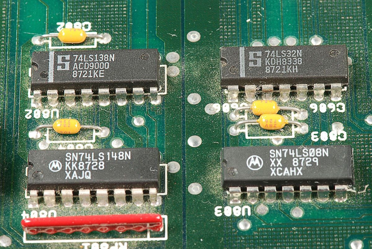
\n\tThis photo shows a Signetics 74LS138N Decoder/Demultiplexer, Signetics 74LS32N Quad 2-Input OR Gate, Motorola SN74LS148N 10-line-to-4-line and 8-line-to-3-line priority encoder, and Motorola SN74LS08N Quad 2-Input AND Gate.
\n
\n\tPhoto by: Bill Detwiler / TechRepublic
\n\tCaption by: Bill Detwiler
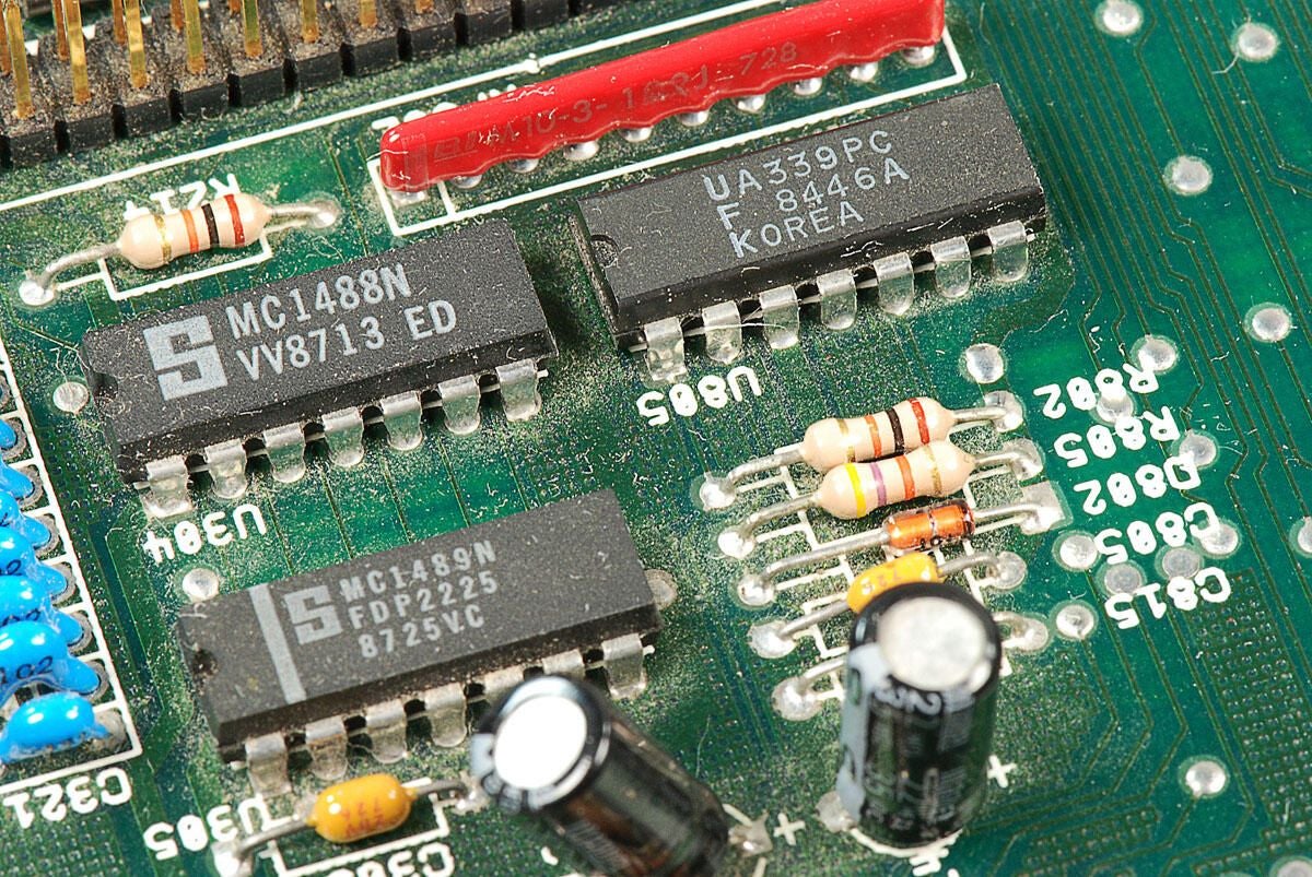
\n\tThis photo shows a Signetics MC1488N quad line driver (upper left), Signetics MC1489N quad line receiver (lower left), and a Fairchild UA339PC voltage comparator (upper right). (At least, I think that’s what the UA339PC chip is.)
\n
\n\tPhoto by: Bill Detwiler / TechRepublic
\n\tCaption by: Bill Detwiler
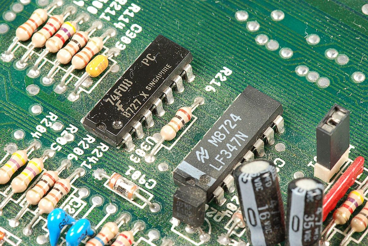
\n\tThe upper chip is a Fairchild 74F08 IC Gate and Quad 2 Input 14-Dip. I’m not sure what the lower chip is, but it has the following marking:
\n
\n\tM8724
\n\tLF347N
\n
\n\tPhoto by: Bill Detwiler / TechRepublic
\n\tCaption by: Bill Detwiler
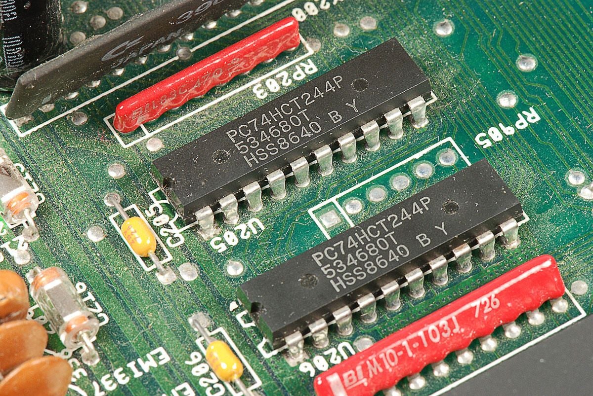
\n\tI believe these chips are Phillips / NXP PC74HCT244P non-inverting-function buffer gates, but I can be sure.
\n
\n\tPhoto by: Bill Detwiler / TechRepublic
\n\tCaption by: Bill Detwiler
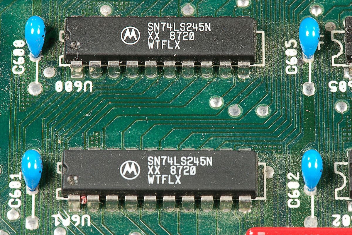
\n\tLooking at their markings, I believe these chips are Motorola SN74LS245N octal bus transceivers.
\n
\n\tPhoto by: Bill Detwiler / TechRepublic
\n\tCaption by: Bill Detwiler
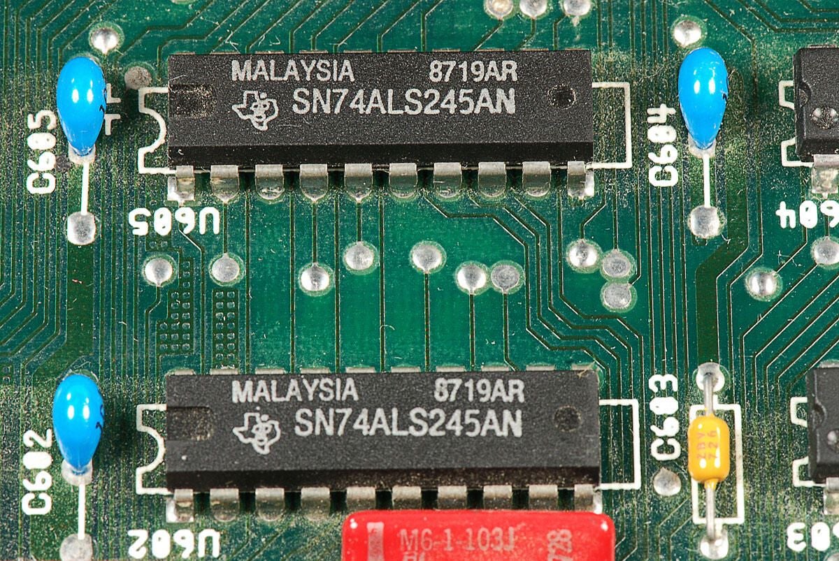
\n\tThe chips in this photo are Texas Instruments SN74ALS245AN octal bus tranceivers.
\n
\n\tPhoto by: Bill Detwiler / TechRepublic
\n\tCaption by: Bill Detwiler
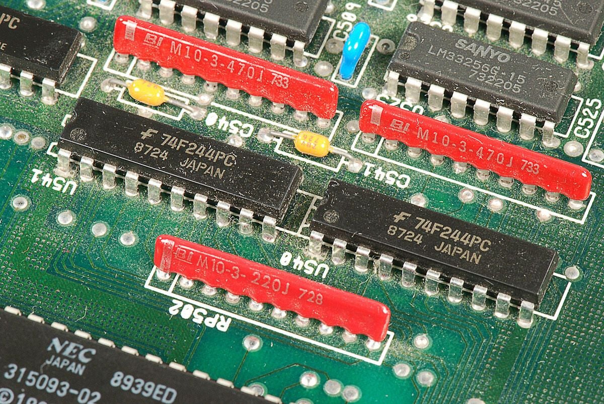
\n\tThese two chips are Fairchild 74F244PC octal buffer and line drivers.
\n
\n\tPhoto by: Bill Detwiler / TechRepublic
\n\tCaption by: Bill Detwiler
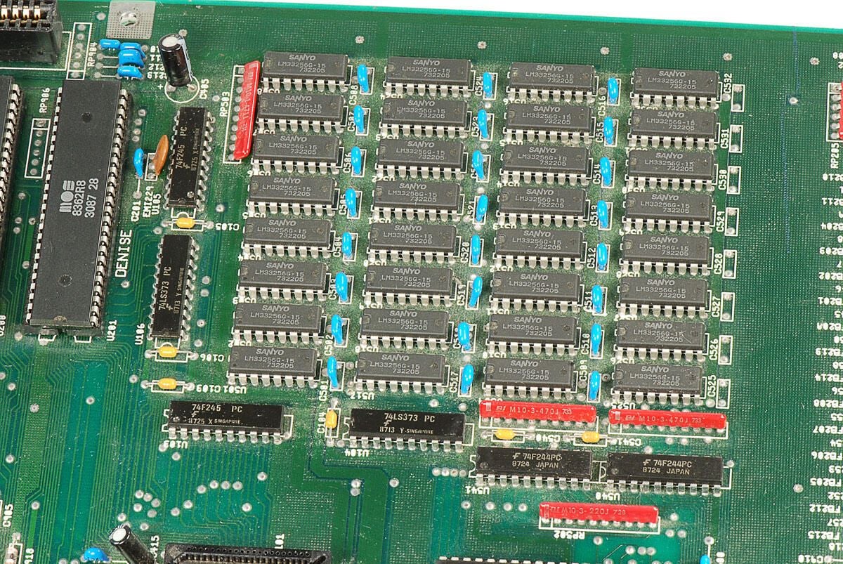
\n\tThe 32 Sanyo LM33256G-15 256kbit memory chips, shown in this photo, provide the Amiga 2000’s 1MB of RAM.
\n
\n\tPhoto by: Bill Detwiler / TechRepublic
\n\tCaption by: Bill Detwiler
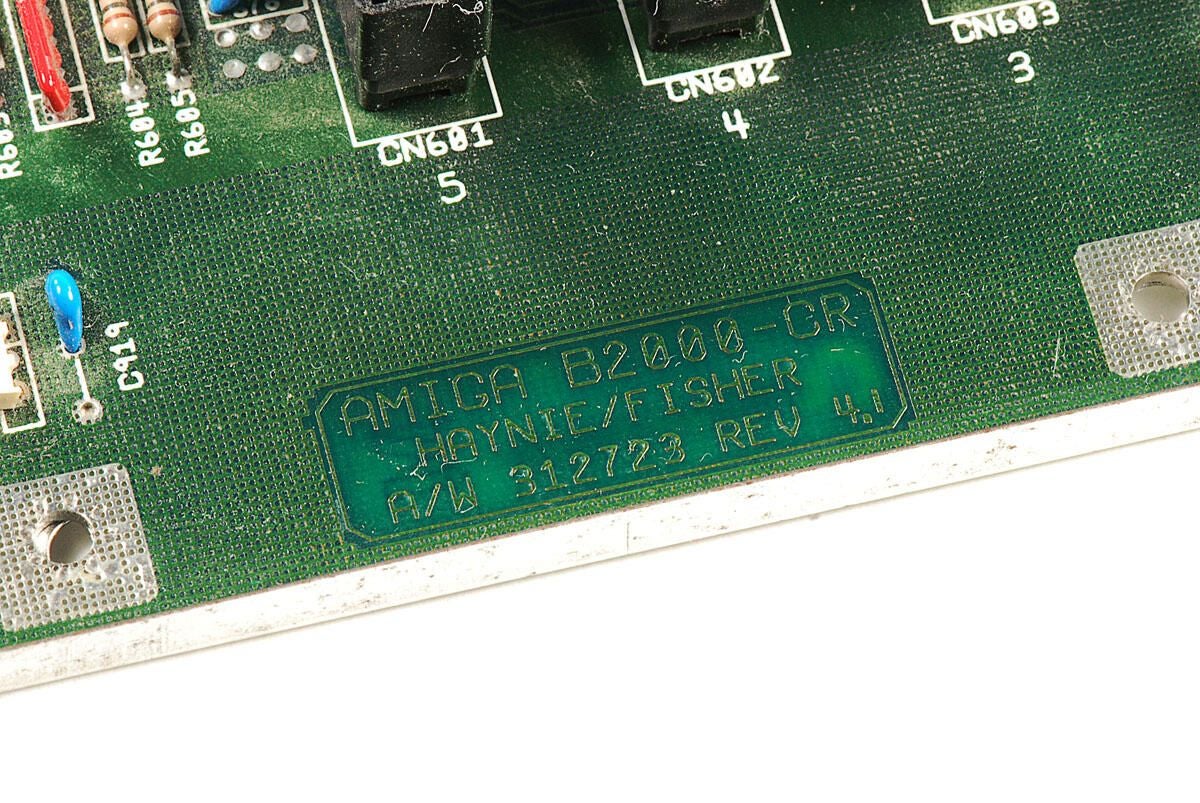
\n\tThis Amiga 2000 has the following markings on the motherboard:
\n
\n\tAMIGA B2000-CR
\n\tHAYNIE/FISHER
\n\tA/W 312723 REV 4.1
\n
\n\tThe original Amiga 2000 (A2000) was designed and manufactured in Germany. It was based on a German Amiga 1000 motherboard. But not long after launch of the A2000, Commodore engineers redesinged the machine, using technology from both the original German design and the Amiga 500.
\n
\n\tThe first set of markings denote this machine as a redesigned Amiga B2000-CR (Cost Reduction). But more interstingly, the markings “HAYNIE/FISHER” refer to Commodore engineers who worked on the B2000-CR. Dave Haynie was primary engineer on the Amiga B2000-CR (Cost Reduction), and Terry Fisher designed the motherboard.
\n
\n\tThis is the first time I have seen the names of a computer’s designers printed on the machine’s motherboard.
\n
\n\tFor more information on the history of the Amiga 2000, including several quotes and posts from Dave Haynie, check out the following links:
\n
\n\t
\n\t
\n\t
\n\t
\n
\n
\n\tPhoto by: Bill Detwiler / TechRepublic
\n\tCaption by: Bill Detwiler
\n\tLike many desktop computers of its time, the Amiga 2000 is built like a tank. It is covered with a heavy metal case, has an internal metal frame that holds the power supply and disk drives, and uses large Phillips screws. Disassembling the Amiga is a dream compared to cracking open todays tablets and smartphones.
\n
\n\tPhoto by: Bill Detwiler / TechRepublic
\n\tCaption by: Bill Detwiler
Bill Detwiler is the Editor for Technical Content and Ecosystem at Celonis. He is the former Editor in Chief of TechRepublic and previous host of TechRepublic's Dynamic Developer podcast and Cracking Open, CNET and TechRepublic's popular online show. Previously, Bill was an IT manager in the social research and energy industries. He has bachelor's and master's degrees from the University of Louisville, where he has also lectured on computer crime and crime prevention.
