U.S. Patent number: 3,541,541
Filed: Jun 21, 1967
Issued: Nov 1970
Inventor: Douglas C. Engelbart
Assignee: Stanford Research Institute
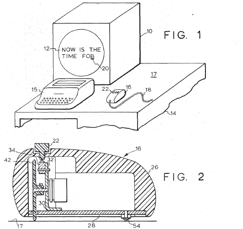
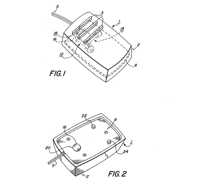
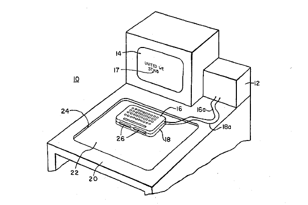
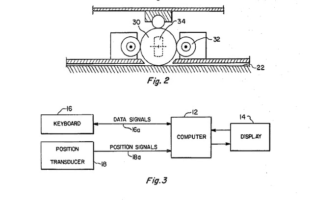
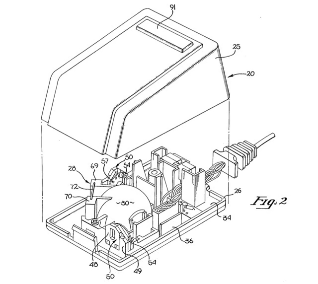
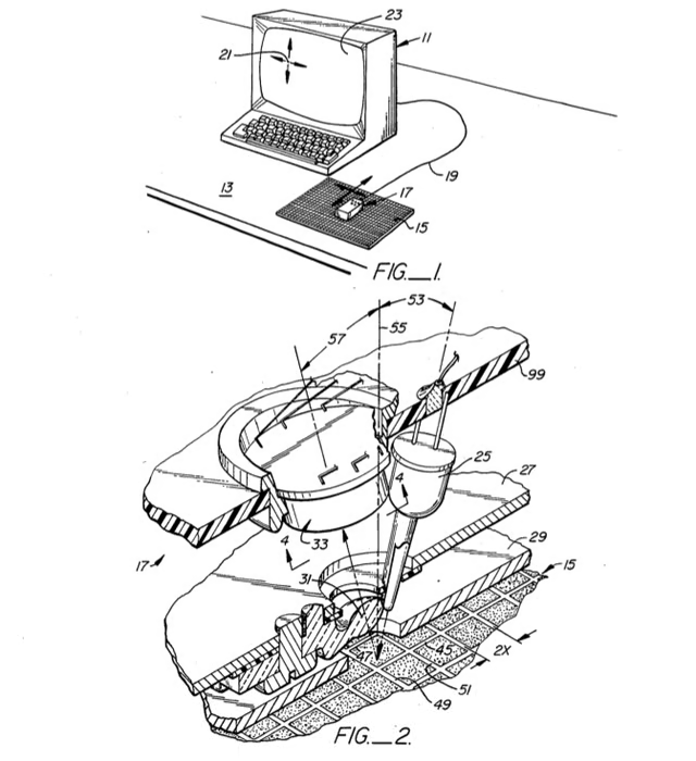
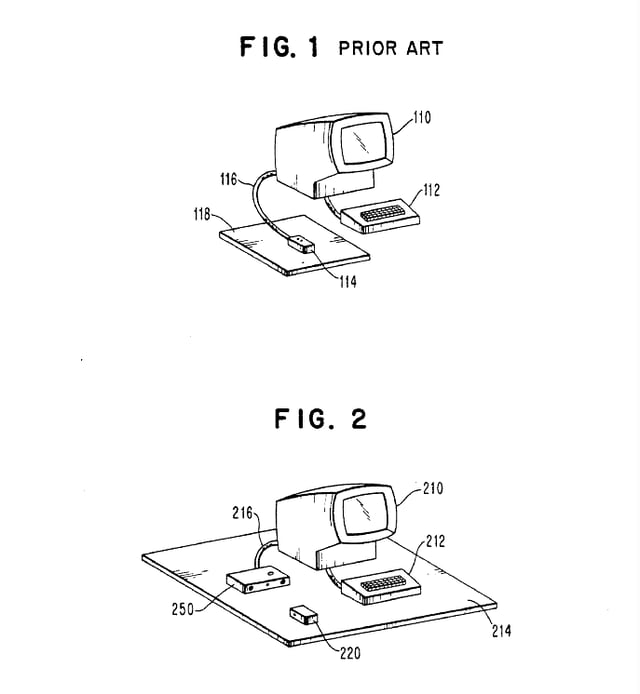
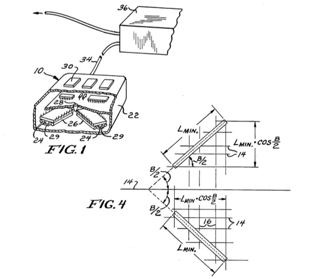
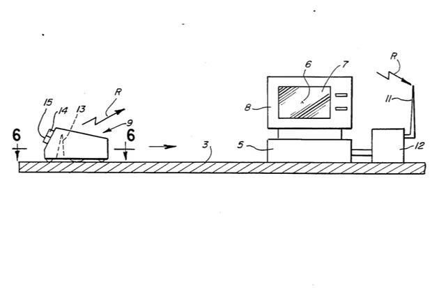
Although the commercial mouse wouldn’t make its debut until 1981, the venerable pointing device began its life much earlier. In 1967, Douglas C. Engelbart filed a patent for a device he called an “X-Y Position Indicator For A Display System.”
The patent describes the devices as follows:
“An X-Y position indicator control for movement by the hand over any surface to move a cursor over the display on a cathode ray tube, the indicators control generating signals indicating its position to cause a cursor to be displayed on the tube at the corresponding position.”
Image taken from U.S. Patent 3,541,541 – Digitized by Google
U.S. Patent number: 3,835,464
Filed: Jan. 11, 1973
Issued: Sept. 10, 1974
Inventor: Ronald E. Rider
Assignee: Xerox Corporation
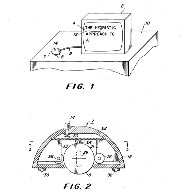
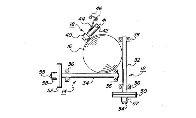
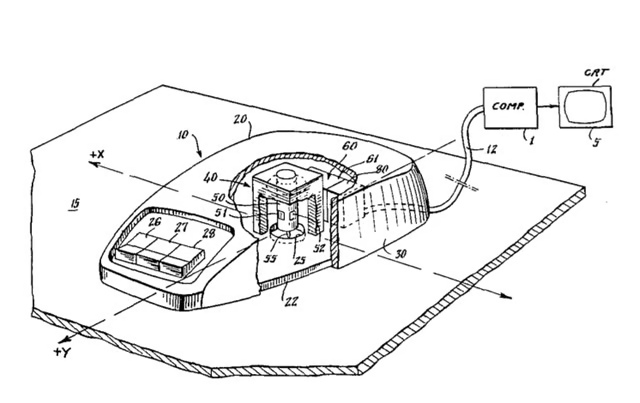
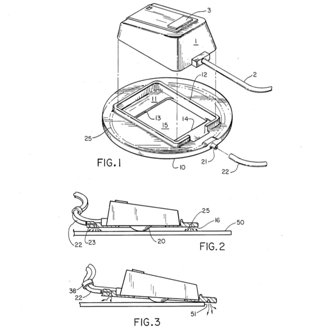
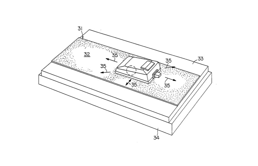
Although Engelbart’s pointer design was revolutionary; the device specified in U.S. Patent 3,541,541 had a significant flaw–it used two wheels to measure movement along the X and Y axes. In 1974, Ronald E. Rider and Xerox were issued a patent for a mouse that utilized a “transport sphere” and “position wheels” to determine the device’s position.
Thanks to Rider’s invention, people would be cleaning the dust from under their mouse’s transport spheres for decades–at least until the invention of the optical mouse.
Image taken from U.S. Patent 3,835,464 – Digitized by Google
U.S. Patent number: 3,892,963
Filed: Dec. 20, 1973
Issued: Jul. 1975
Inventor: Hawley at al.
Assignee: Xerox Corporation
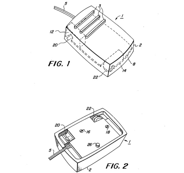
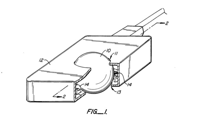
Despite touting the transport sphere’s superiority to X and Y axis wheels in U.S. Patent 3,835,464, Xerox filed another patent late the same year that built upon the Engelbart’s two-wheel design.
In U.S. Patent 3,892,963, inventors Jack S. Hawley, Roger D. Bates, and Charles P. Thacker, outline a new way to measure the movement of the X- and Y-axis wheels.
Image taken from U.S. Patent 3,892,963 – Digitized by Google
U.S. Patent number: 3,892,963
Filed: Dec. 20, 1973
Issued: Jul. 1975
Inventor: Hawley at al.
Assignee: Xerox Corporation
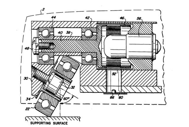
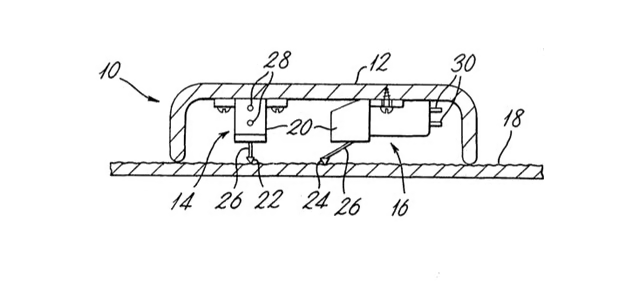
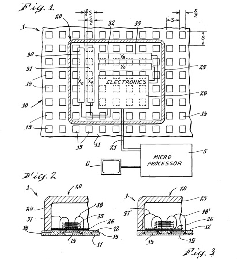
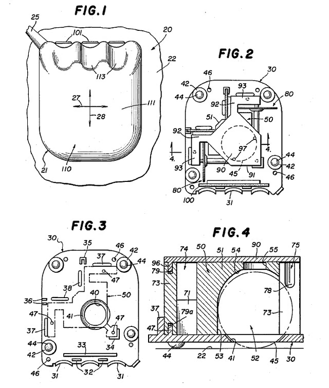
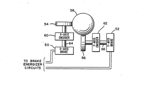
This drawing shows the inner-workings of Hawley, Bates, and Thacker’s design for computer mouse X- and Y-axis wheels. According to U.S. Patent 3,892,963:
“the X and Y wheels are respectively coupled to transducer elements which translate the rotation of the wheels into X and Y positional signals.”
Image taken from U.S. Patent 3,892,963 – Digitized by Google
U.S. Patent number: 3,987,685
Filed: Dec. 16, 1974
Issued: Oct. 26, 1976
Inventor: Willard J. Opocensky
Assignee: Xerox Corporation
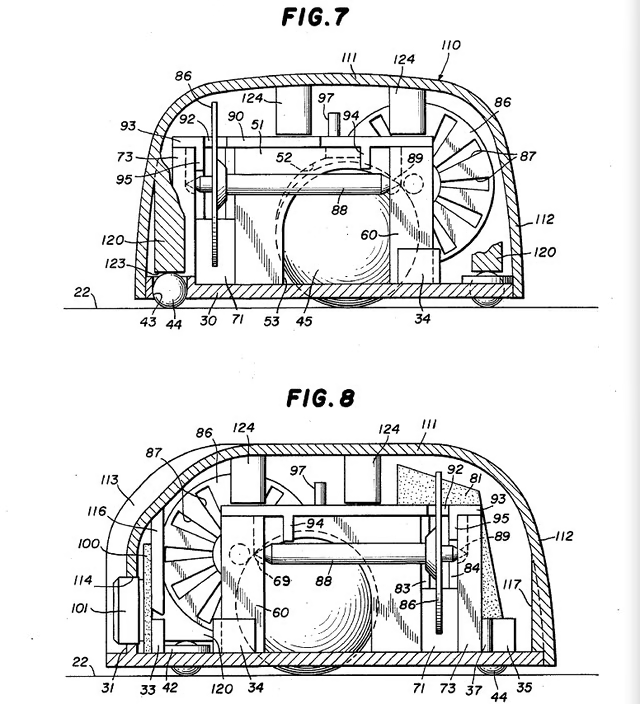
A year after Xerox filed their first patent for a mouse using a transport sphere, the company and inventor Willard J. Opocensky filed for a patent that improved upon the design. The new mouse would replace the position wheels with “rotatable shafts” that would measure the sphere’s movement.
Image taken from U.S. Patent 3,987,685 – Digitized by Google
U.S. Patent number: 3,987,685
Filed: Dec. 16, 1974
Issued: Oct. 26, 1976
Inventor: Willard J. Opocensky
Assignee: Xerox Corporation
As described in U.S. Patent 3,987,685:
“The device includes a control mechanism that comprises a transport sphere coupled with rotatable shafts which represent the position of the device in terms of Cartesian coordinates.”
Image taken from U.S. Patent 3,987,685 – Digitized by Google
U.S. Patent number: 4,303,914
Filed: Mar. 2, 1979
Issued: Dec. 1, 1981
Inventor: Ian Page
Assignee: National Research Development Corporation
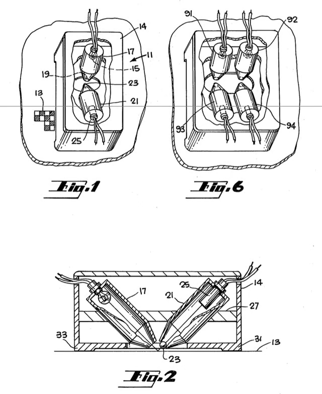
After a decade of mouse designs featuring wheels and transport spheres, the 1980s saw the introduction of two new mouse designs–audio and optical. Ian Page’s mouse combined a pair of piezo-electric audio pick-ups and styli to measure the mouse movement across a surface. According to the patent:
“the sensing means may include for each axis a piezo-electric crystal and a stylus which in use lies in contact with the plane surface, the stylus being so arranged that during motion along the relevant axis a stress is transmitted to the crystal in a direction determined by the direction of motion of the stylus whenever such motion is impeded by a textural feature of the surface.”
Image taken from U.S. Patent 4,303,914 – Digitized by Google
U.S. Patent number: 4,390,873
Filed: May 18, 1981
Issued: Jun. 28, 1983
Inventor: Steven T. Kirsch
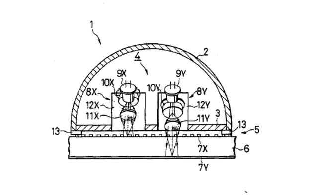
In 1983, Steven T. Kirsch was granted a patent for a mouse the uses a light source, a four-quadrant detector, and a surface printed with a special pattern. Kirsch describes the benefits of his design in U.S. Patent 3,987,685:
” One of the advantages of this system over mechanical mice is that it is relatively simple to manufacture in large quantities because there are no close tolerance parts. ”
He goes on to list other advantages, such as:
Unfortunately, Kirsch’s design had two drawbacks. It required a special surface on which to use the mouse, and that surface had to be oriented a certain way.
Image taken from U.S. Patent 4,390,873 – Digitized by Google
U.S. Patent number: 4,369,439
Filed: Jan. 14, 1981
Issued: Jan. 18, 1983
Inventor: Michael S. Broos
Asignee: Massachusetts Institute of Technology
surface.
Inventor Michael S. Broos wanted to make the process of using a mouse while entering text via a keyboard easier. And in 1983, a patent was issued for his device the combined a standard keyboard and mouse.
Image taken from U.S. Patent 4,369,439 – Digitized by Google
U.S. Patent number: 4,369,439
Filed: Jan. 14, 1981
Issued: Jan. 18, 1983
Inventor: Michael S. Broos
Asignee: Massachusetts Institute of Technology
As this patent drawing shows, Broos’ mouse/keyboard combo would you a traditional trackball to measure the device’s movement across the the work surface.
Image taken from U.S. Patent 4,369,439 – Digitized by Google
U.S. Patent number: 4,409,479
Filed: Dec. 3, 1981
Issued: Oct. 11, 1983
Inventor: Sprague et al.
Assignee: Xerox Corporation
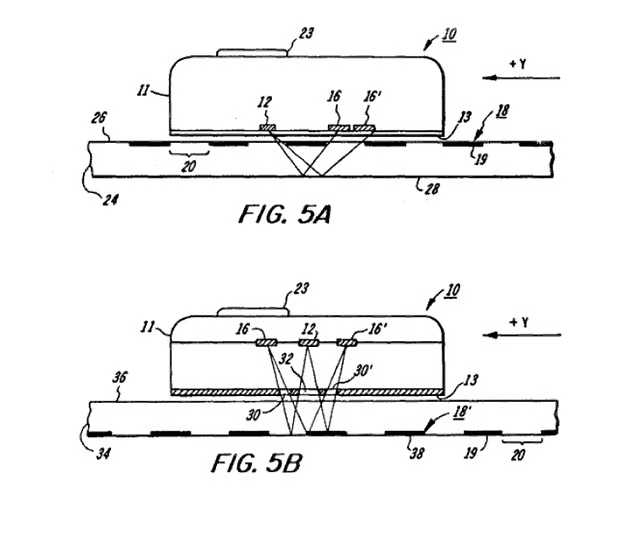
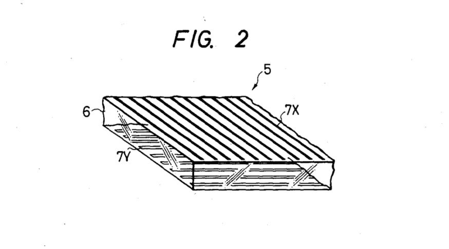
Steven Kirsch wasn’t the only inventor working on an optical mouse. Robert A. Sprague and Donald R. Scifres designed a mouse with optical transducers that was designed to work with a special “grid pattern” surface.
Image taken from U.S. Patent 4,409,479 – Digitized by Google
U.S. Patent number: 4,409,479
Filed: Dec. 3, 1981
Issued: Oct. 11, 1983
Inventor: Sprague et al.
Assignee: Xerox Corporation
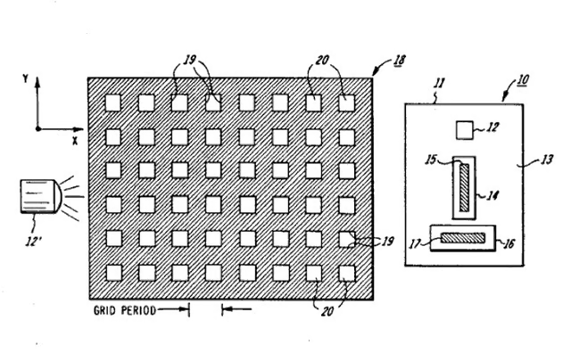
This patent drawing shows special surface Sprague and Scifres’ mouse was designed to use. The pair described the surface in the patent as follows:
“The device relies on a planar grid pattern comprising orthogonally positioned grid lines of uniform spacing, one line and spacing defining a grid period.”
Image taken from U.S. Patent 4,409,479 – Digitized by Google
U.S. Patent number: 4,464,652
Filed: Jul. 19, 1982
Issued: Aug. 7, 1984
Inventor: Papson et al.
Assignee: Apple Computer, Inc.
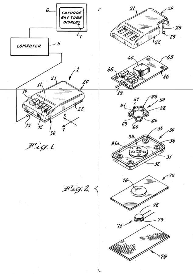
Apple entered the mouse patent game in 1984, when they were granted U.S. Patent 4,464,652. Inventors William F. Lapson and William D. Atkinson believed their mouse improved upon the prior designs because it was less susceptible to wear, less likely to lose accuracy over time, and cheaper to manufacture. This mouse shipped with the Lisa.
Image taken from U.S. Patent 4,464,652 – Digitized by Google
U.S. Patent number: 4,464,652
Filed: Jul. 19, 1982
Issued: Aug. 7, 1984
Inventor: Papson et al.
Assignee: Apple Computer, Inc.
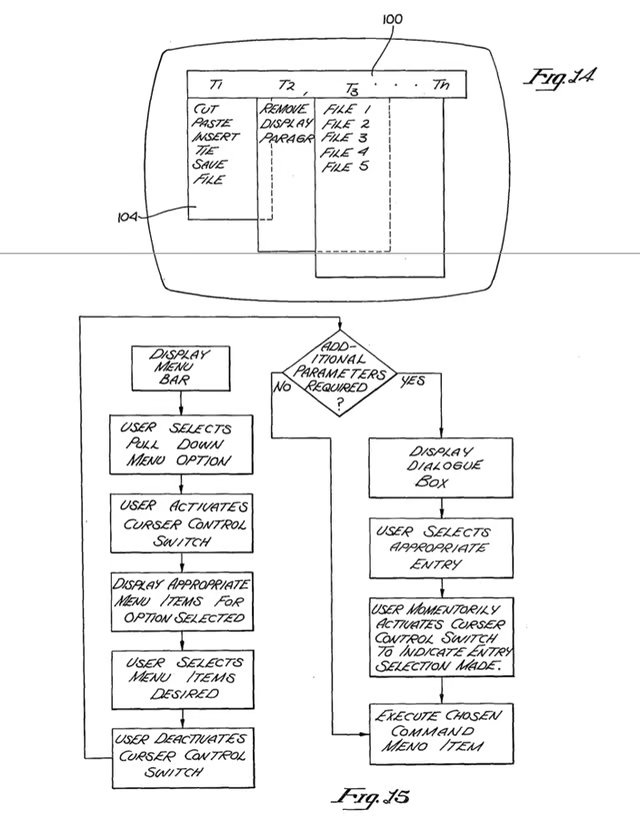
Not only did Lapson and Atkinson describe a new mouse design, but the pair also outlined a menu-based display system for use with the pointing device. According U.S. Patent 4,464,562:
“Appropriate programming of the computer is provided such that a “menu” bar 100 comprising a variety of command options indicated by titles (for example, T1, T2, T3 … T4), is displayed across the CRT screen or the like as shown in FIG. 14. If a particular title (for example T1) is selected, one or more sub-command items appear to the user to be “pulled down” form the menu bar 100.”
Image taken from U.S. Patent 4,464,652 – Digitized by Google
U.S. Patent number: 4,514,726
Filed: Aug 19, 1983
Issued: Apr 30, 1985
Inventor: Albert L. Whetstone et al.
Assignee: Display Interface Corporation
Although Ian Page’s earlier audio-based mouse never gained commercial acceptance, Albert L. Whetstone, Kerry L. Shaklee, and Khosrow Modjallal revisited the idea in the early 1980s. But unlike Page’s design, their mouse would use a “displacement pad with associated displacement transducer means and velocity/distance transducer means.” Moving the mouse would cause “displacement of the displacement pad produces direction-indicative signals and causing vibration of the velocity/distance transducer produces distance-indicative signals.”
Image taken from U.S. Patent 4,514,726 – Digitized by Google
U.S. Patent number: 4,521,772
Filed: Jan. 13, 1983
Issued: Jun. 4, 1985
Inventor: Richard F. Lyon
Assignees: Xerox Corporation
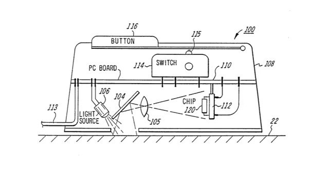
A few years after Krisch filed his patent for a mouse with a light source and four-quadrant detector, Richard Lyon offered his take on the optical mouse. Lyon’s design used a light source and an IC chip that contained an optical sensor and motion detector. As with Kirsch’s design, Lyon’s mouse required a special surface–a field of light dots on a dark background. But unlike the earlier mouse, Lyon’s design didn’t rely on the pad for its x-y orientation. Instead, it used the x-y coordinate system of the mouse body and used the pad’s embedded pattern to track the mouse’s motion relative to its body.
Image taken from U.S. Patent 4,521,772- Digitized by Google
U.S. Patent number: 4,543,571
Filed: Aug Nov. 5, 1982
Issued: Sep. 24, 1985
Inventor: Bilbrey et al.
Assignees: Universal Supply, Inc. and Edward F. Towers
In 1985, Inventors Robert A. Bilbrey and Bruce R. Koball were granted a patent for a mouse that combined both optical and mechanical means for measuring the device’s movement. According to their patent:
“The optical system is limited to detecting the distance traveled by the mouse across the pattern, a mechanical displacement device within the mouse being utilized to detect the direction of the movement. Signals from the optical distance detector and the mechanical direction detector are combined to drive the cursor in a controlled direction across a cathode ray tube or other display device.”
Image taken from U.S. Patent 4,543,571 – Digitized by Google
U.S. Patent number: 4,550,316
Filed: Apr. 29, 1983
Issued: Oct. 29, 1985
Inventor: Whetstone et al.
Assignee: Display Interface Corp.
Instead of wheels, a transport sphere, or optical detectors, inventors Albert L. Whetstone and Kerry L. Shaklee designed a mouse with and embedded stylus. As you moved the mouse across a surface, the stylus would bend and vibrate. According to the patent, two methods could be used to measure this bending and vibration:
“Strain gauges, mounted directly to the stylus or to a diaphragm mounting the stylus, are used to ascertain bending and vibration. Photocell means are also disclosed to ascertain bending a [sic] vibration of the stylus.”
Image taken from U.S. Patent 4,550,316 – Digitized by Google
U.S. Patent number: 4,562,347
Filed: Sep. 23, 1983
Issued: Dec. 31, 1985
Inventor: Hovey et al.
Assignee: Trace Systems, Inc.
Some argue that a mouse with a transport sphere, or ball, is basically an up-side-down trackball. Well in 1985, inventors Dean A. Hovey, Douglas R. Grundstrom, and James R. Yurchenco were issued a patent for a mouse that combined both pointing devices. As shown in this drawing, the transport sphere inside their mouse could protrude from both the top and bottom of the housing.
According to the patent, their device could “be moved over a surface, so as to function as a mouse, or can be supported by its housing, with motive force applied to the portion of the spherical member protruding from the top aperture, so as to function as a trackball.”
Image taken from U.S. Patent 4,562,347 – Digitized by Google
U.S. Patent number: 4,564,835
Filed: Dec. 13, 1982
Issued: Jan. 14, 1986
Inventor: Satish K. Dhawan
Seeking to improve on both electromechanical and optical mice, inventor Satish Dhawan designed a mouse that measures movement by detecting changes in an electrical field generated between the mouse and special mouse tablet. Shown in this drawing, the mouse tablet would have a “repetitive, regular pattern of spaced-apart conductive pixels.” According to the patent, the mouse would contain “coupling elements which electrically field couple with the pixels,” “means for establishing an electrical field from the coupling elements,” and a “means for detecting changes in that field.”
Dhawan believed mice using this design would be cheaper to manufacture and offer more precise cursor movement than electromechanical mice. The design would also allow drawings or other papers (like building plans or mechanical diagrams) to be placed between the mouse and mouse surface. Lastly, Dhawan thought the design would be more tolerant of a dirty mouse surface than optical mice of the time.
Image taken from U.S. Patent 4,564,835 – Digitized by Google
U.S. Patent number: 4,578,674
Filed: Apr. 20, 1983
Issued: Mar. 25, 1986
Inventor: Baker et al.
Asignee: International Business Machines Corporation
By the mid-1980s it was time for the computer mouse to lose its tail. Inventors David C. Baker, David F. Bantz, and Gregory A. Flurry designed an interesting mouse and control base system. Instead of a mechanism inside the mouse body measuring the mouse motion and transmitting that information to the receiver, their system would transmit and receive ultrasonic or infrared signals between the mouse and control base. The mouse’ initial location and movement would be calculated by measuring the Doppler shift of the signals.
Image taken from U.S. Patent 4,578,674 – Digitized by Google
U.S. Patent number: 4,595,070
Filed: Jun. 27, 1984
Issued: Jun. 17, 1986
Inventor: Richard P. Hodges
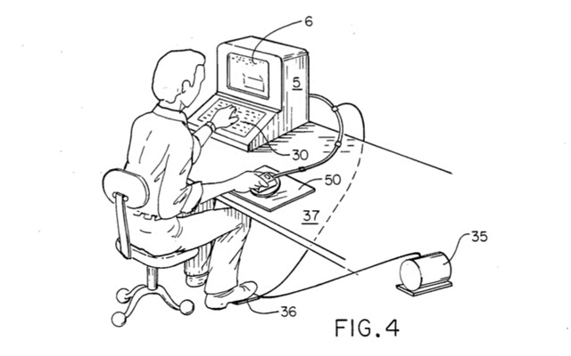
While others were busy building better mice, inventor Richard Hodges designed a rather curious mouse accessory. In 1986, Hodges was issued a patent for a device that would support a mouse “above a working surface on a cushion of air or other gaseous fluid.” Why did Hodge think his device was needed? According to the patent:
“A major drawback to the current use of a computer mouse has been the fatigue associated with the precise movement required of the mouse. Extended use of a computer mouse while performing highly detailed work can produce operator tensions and associated fatigue, together with a reduction in operator performance.”
Image taken from U.S. Patent 4,595,070 – Digitized by Google
U.S. Patent number: 4,595,070
Filed: Jun. 27, 1984
Issued: Jun. 17, 1986
Inventor: Richard P. Hodges
While Richard Hodges’ concern about operator fatigue and loss of performance from extended mouse use are certainly valid, his air-glide mouse platform was just impractical. As shown in this drawing, a pump, placed near the computer, would supply air to the mouse platform. The user could control the flow of air via a foot pedal.
Image taken from U.S. Patent 4,595,070 – Digitized by Google
U.S. Patent number: 4,623,787
Filed: Dec 5, 1983
Issued: Nov. 18, 1986
Inventor: Syng N. Kim
Asignee: Wico Corporation
Inventor Syng Kim sought to improve the design of traditional trackball mice by using “photoelectric transducer elements” to measure the rotation of the X and Y rotational shafts.
Image taken from U.S. Patent 4,623,787 – Digitized by Google
U.S. Patent number: 4,623,787
Filed: Dec 5, 1983
Issued: Nov. 18, 1986
Inventor: Syng N. Kim
Asignee: Wico Corporation
As this patent drawing shows, one end of each shaft is connected to a “code wheel” which contains several slots. An LED light source is placed on one side of the slot, and a light-responsive element is place on the other side. As the user moves the mouse across the work surface, the trackball’s movement causes the each shaft to rotate. As the shafts rotate, so do the attached code wheels. As the wheels rotate, the light beam between the LED and the light detector is interrupted. The mouse’s internal circuitry can then translate the frequency of interruption into signals that indicate the speed of the trackball and therefore the speed of the mouse.
Image taken from U.S. Patent 4,623,787 – Digitized by Google
U.S. Patent number: 4,647,771
Filed: Dec. 5, 1984
Issued: Mar 3, 1987
Inventor: Takaaki Kato
Asignee: Nissin Kohki Co. Ltd.
Takaaki Kato’s creation was another combination of an optical mouse and special surface. But unlike previous designs, Kato’s surface would be a “transparent substrate” two separate line patterns embedded within the substrate at two different depths. When viewed from the top the two patterns would form a grid. According to the patent:
“Because the first and second line patterns are located at different distances from the optical system [the mouse], light reflected from the two patterns can be separately focused to prevent interference between the two patterns.” Kato claimed that the difference in reflectivity between the two patterns would make it easier for the mouse to count the lines and measure its movement.
Image taken from U.S. Patent 4,647,771 – Digitized by Google
U.S. Patent number: 4,647,771
Filed: Dec. 5, 1984
Issued: Mar 3, 1987
Inventor: Takaaki Kato
Asignee: Nissin Kohki Co. Ltd.
This drawing from the patent shows Kato’s “transparent substrate” with the two separate line patterns.
Image taken from U.S. Patent 4,647,771 – Digitized by Google
U.S. Patent number: 4,686,329
Filed: Jun. 21, 1985
Issued: Aug. 11, 1987
Inventor: Stephen A. Joyce
Asignee: Advanced Robotic Technology, Inc.
Another inventor to design a mouse/tablet system was Stephen A. Joyce. In 1987, a patent was issued for his design of an “apparatus for determining the absolute position of a point on a surface including a tablet or overlay and a moveable mouse-type cursor.”
Because neither the trackball nor optical mice of the day could determine their absolute position relative to the surface they were on, Joyce did not believe they were adequate for tracing points on an existing document, such as a map. And although mice did exist that could determine their absolute position, such as Dhawan’s Field-Coupled Pointing Device, Joyce claimed the surfaces used by these mice were “relatively expensive” and therefore “unsuitable for most home computer and similar lower end applications.”
Joyce’s design used “a pair of solid-state photosensitive arrays, or similar, optical arrays” and a transparent, patterned surface to determine the mouse’s absolute position. Because the surface would be transparent, it could be placed over the documents you wanted to trace.
Image taken from U.S. Patent 4,686,329 – Digitized by Google
U.S. Patent number: 4,754,268
Filed: Jun. Aug. 23, 1985
Issued: Jun. 28, 1988
Inventor: Akira Mori
Asignee: Mitsuboshi Belting Ltd.
Unlike Baker, Bantz, and Flurry’s earlier wireless mouse design, Mori’s mouse was designed to functioned more like modern day wireless mouse. The mouse body carried a power source, means to calculate its position and movement, and send that information to the computer. The system would use radio signals to carry the information.
Image taken from U.S. Patent 4,754,268 – Digitized by Google
U.S. Patent number: 4,760,618
Filed: Jun. Apr. 14, 1987
Issued: Aug. 2, 1988
Inventor: Stephen R. Chapin, Jr.
As the trackball mice of the 1980s were prone to collect dirt and dust inside their housings, users would commonly need to remove the trackball and clean the mouse’s trackball chamber and sensors. In 1988, inventor Stephen R. Chapin was issued a patent for a mouse cleaning system that used a special trackball having a “hook” VELCRO surface and a pad covered with a “loop” VELCRO surface.
The mouse’s regular trackball would be temporarily replaced with the VELCRO ball, and as you moved the mouse back and forth on the VELCRO pad, the ball would “scrub” the inside of the trackball chamber.
Image taken from U.S. Patent 4,760,618 – Digitized by Google
U.S. Patent number: 4,868,549
Filed: Jun. May. 18, 1987
Issued: Sep. 19, 1989
Inventor: Affinito et al.
Asignee: International Business Machines Corporation
The mouse took another leap forward the late 1980s, when inventors Frank J. Affinito and John F. Beetem designed a mouse that would provide the user “resistive feedback” of the cursor’s screen position. The pair describe this feedback in their patent filing:
“It is believed that there is a need in this technical area for a mouse having a feedback means wherein a clearly recognizable indication is fed back to the mouse that is apparent to the operator when the movement of the mouse had caused the cursor “to arrive” at some predetermined position or neighborhood on the screen.”
Image taken from U.S. Patent 4,868,549 – Digitized by Google
Bill Detwiler is the Editor for Technical Content and Ecosystem at Celonis. He is the former Editor in Chief of TechRepublic and previous host of TechRepublic's Dynamic Developer podcast and Cracking Open, CNET and TechRepublic's popular online show. Previously, Bill was an IT manager in the social research and energy industries. He has bachelor's and master's degrees from the University of Louisville, where he has also lectured on computer crime and crime prevention.