\n\tExplore the inner workings of an entry level all-in-one printer, as Erik Eckel deconstructs a Lexmark 2500 multifunction printer.
\n\t
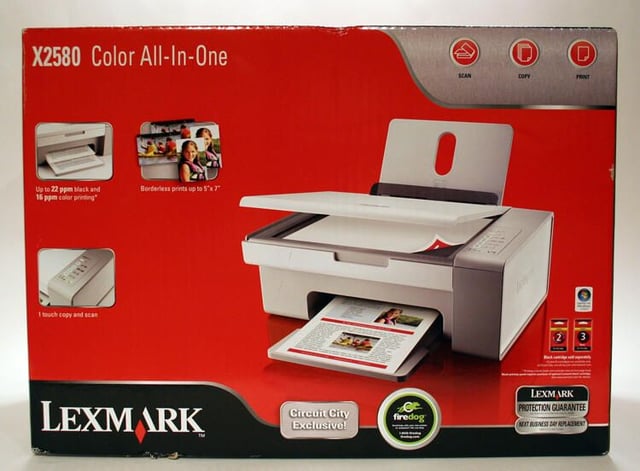
\n\tThe Lexmark 2500 All-In-One printer includes fax, copying, scanning and printing capabilities. View Erik Eckel’s Right Tool gallery review of the Lexmark 2500 All-In-One here.
\n
\n\t\n\n
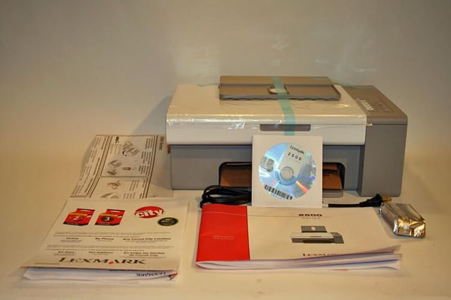
The Lexmark 2500 Series multifunction printer ships with everything seen here.
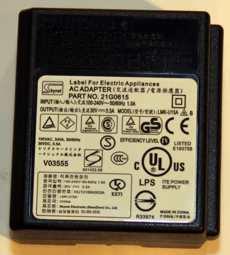
The Lexmark 2500’s power adapter tucks inside a space reserved for it in the printer’s backside.
Made in China, the AC adapter converts wall current to 30 volts.
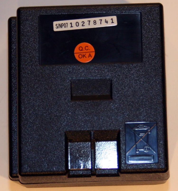
In this view you can see the metallic connectors the AC adapter uses to transfer its converted electrical current to the printer.
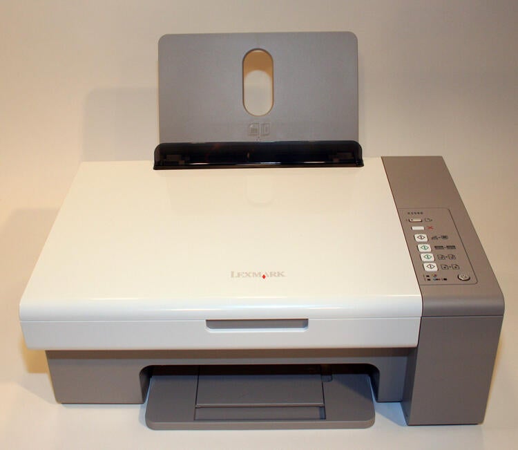
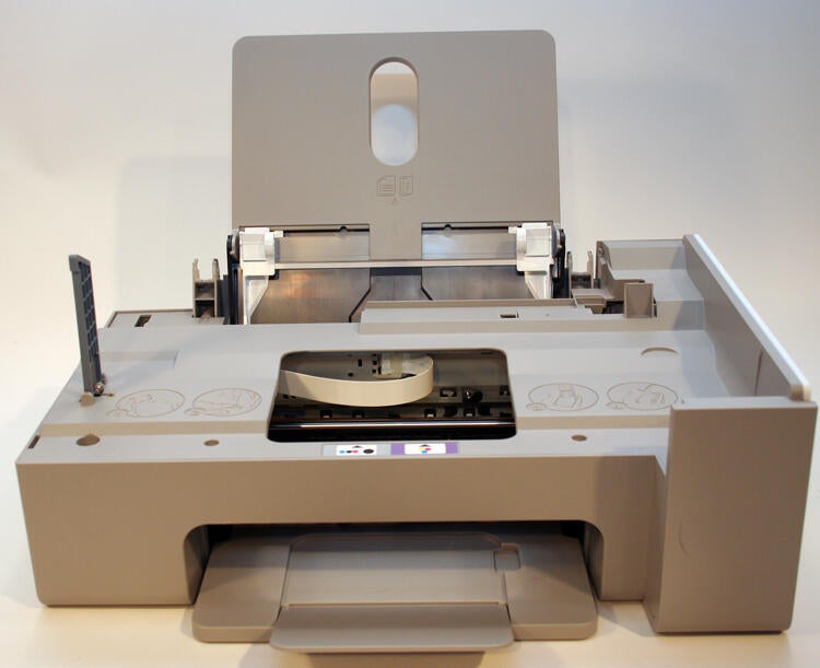
The Lexmark 2500 features a paper tray (at the top) capable of holding about 50 pages of paper. The device ejects completed printouts using the paper tray on the bottom.
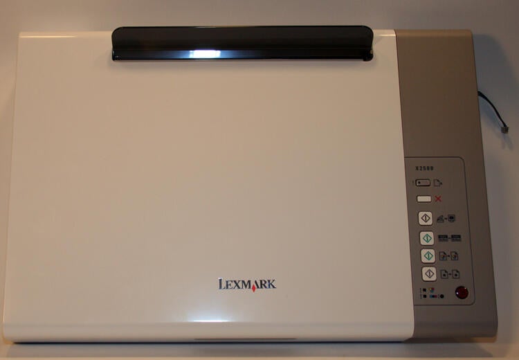
Frequently used features, meanwhile, are easily accessed using the device’s front panel controls.
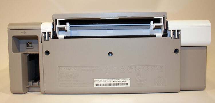
Here’s a view of the rear of the Lexmark 2500 Series printer.
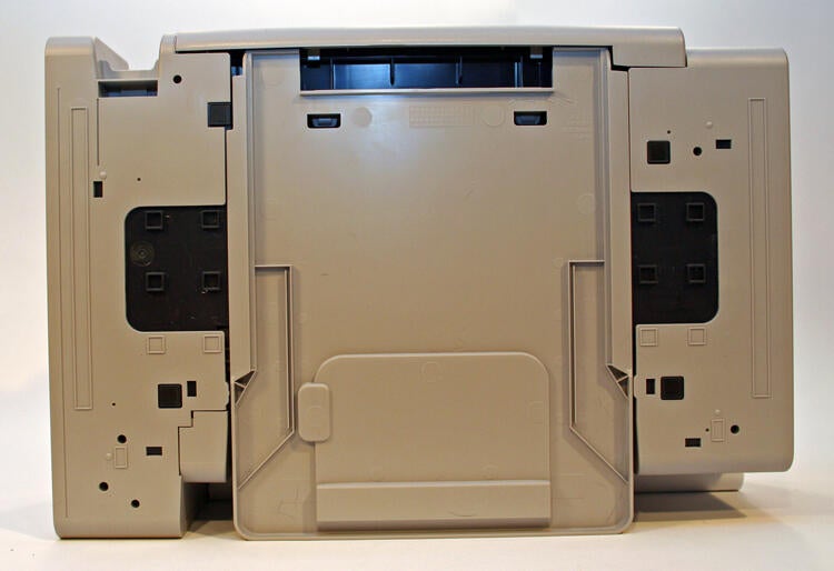
Here’s a view of the Lexmark 2500 Series printers’ undercarriage.
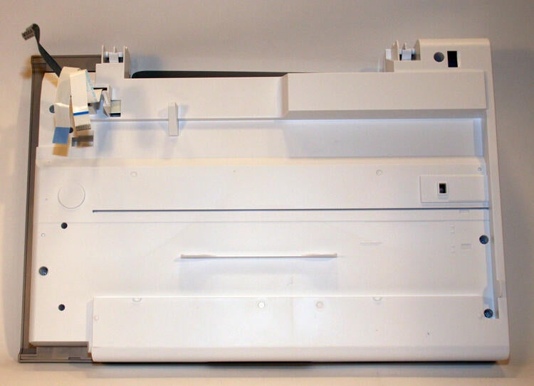
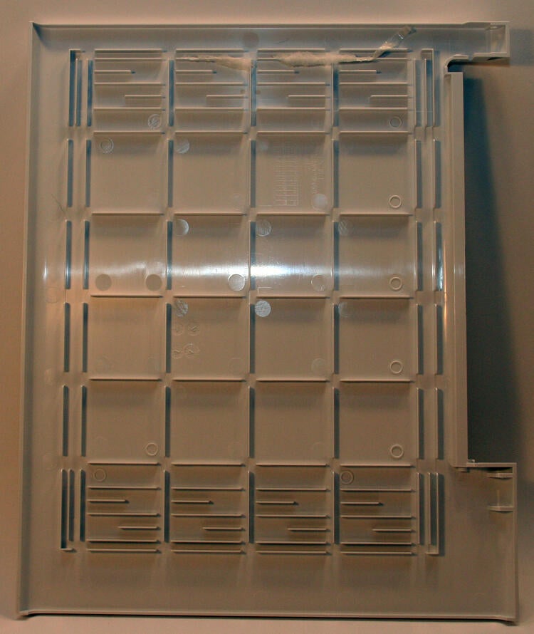
Here you can see the flatbed scanner assembly removed from the printer. This view shows the bottom of the scanner assembly, whose data cable connections are visible in the top left corner.
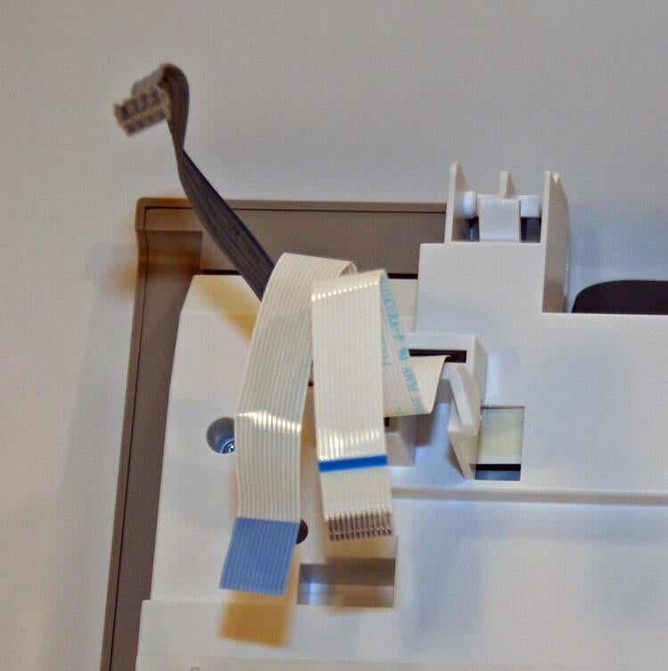
Here’s a close-up view of the data cables used to control the scanner mechanism.
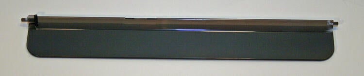
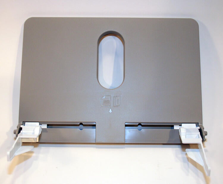
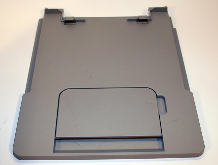
Here’s a top side view of the scanner lid. Perched atop is the (smoke-colored) paper guide that usually serves to hold paper within the supply tray.
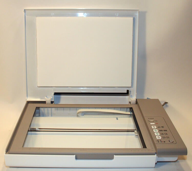
The flatbed scanner assembly, as viewed from the front with the lid open after being removed from the main Lexmark 2500 body.
A small piece, but a critical one nonetheless, the spring-loaded paper guide helps ensure supply paper enters the printer smoothly and without jams.
Here you can see the foam that sits beneath the scanner’s lid. In addition to keeping documents stationary, the foam helps produce better quality scans by preventing bleed through.
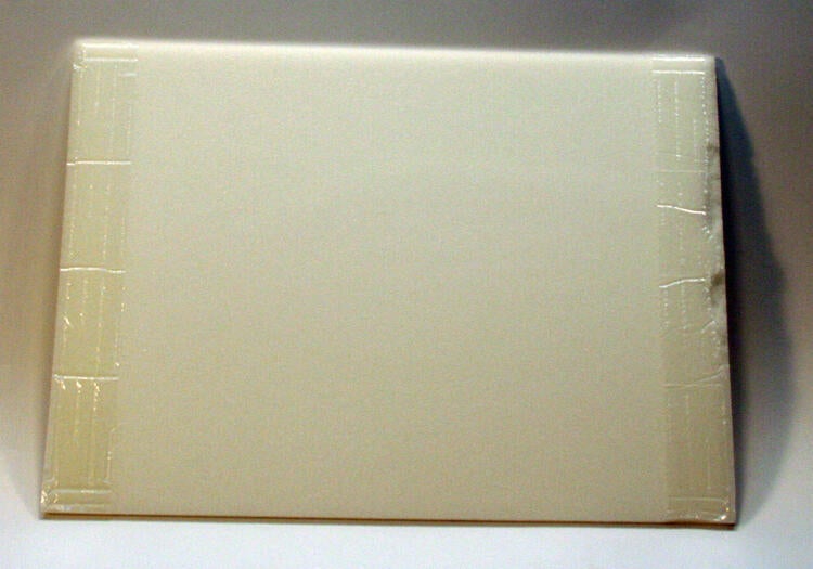
This plastic lid typically holds the foam pad that sits beneath the lid. As the foam’s been removed from this photo, you can see the lid’s naked inside cover.
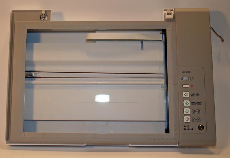
Once the scanner lid is removed, the flatbed scanner appears as shown here.
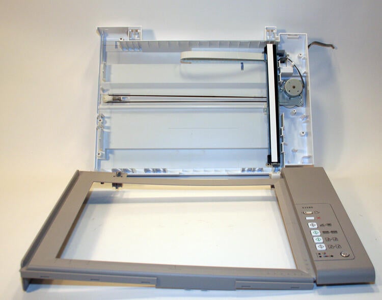
Removing a few fasteners enables removing this portion of the scanner and lid assembly. With the lid open (and its inside cover removed), the motor that drives the actual scanner arm is visible.
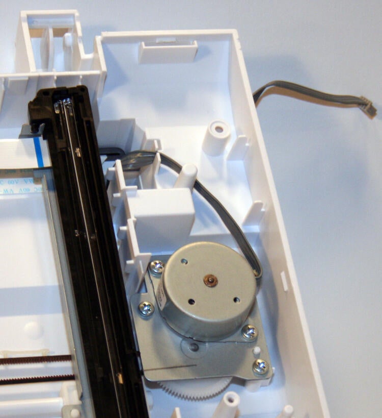
Here’s a close-up of scanner motor assembly from the Lexmark 2500 Series printer.
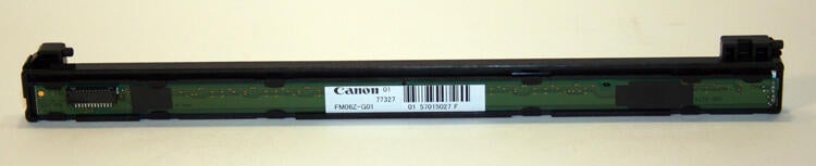
Closer inspection of the scanner assembly reveals that it was manufactured by Canon.
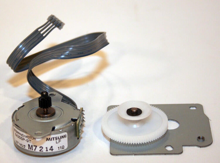
The scanner motor, manufactured by Mitsumi, and the fearing used to help step the scanner arm across the flatbed glass, come free with the removal of a couple screws.
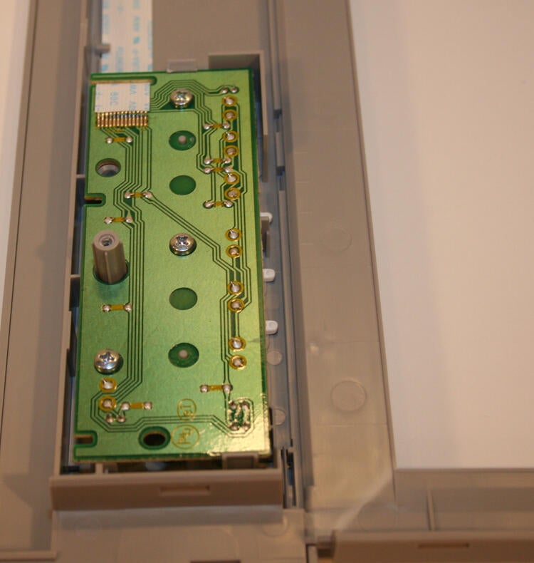
This is the circuit board that sits beneath the Lexmark 2500’s front-panel controls. In addition to powering the unit on and off, this circuit board transmits copy and print requests.
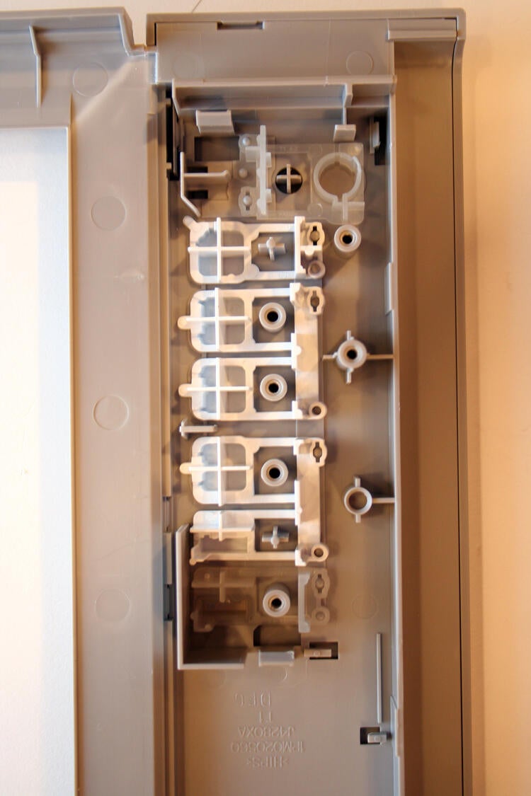
Here’s a view of the print control buttons with the circuit board removed.
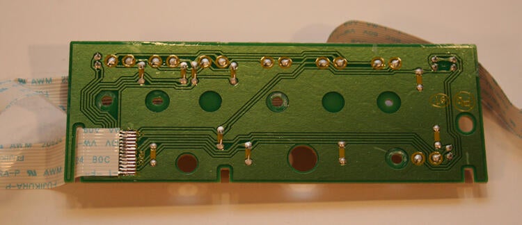
Here’s a view of the print controls circuit board’s backside, once it’s been removed from the printer.
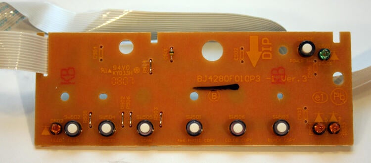
Viewing the print control board straight-on reveals its capacitors.
Here’s the 2500 Series’ main printer engine. With the main case removed, this assembly possesses most of the actual printing equipment and electronic controls.

Here you can see the plastic inlay that provides structural support to the printer as well as access (through the prominent cutout visible in the front) to replacing inkjet cartridges.
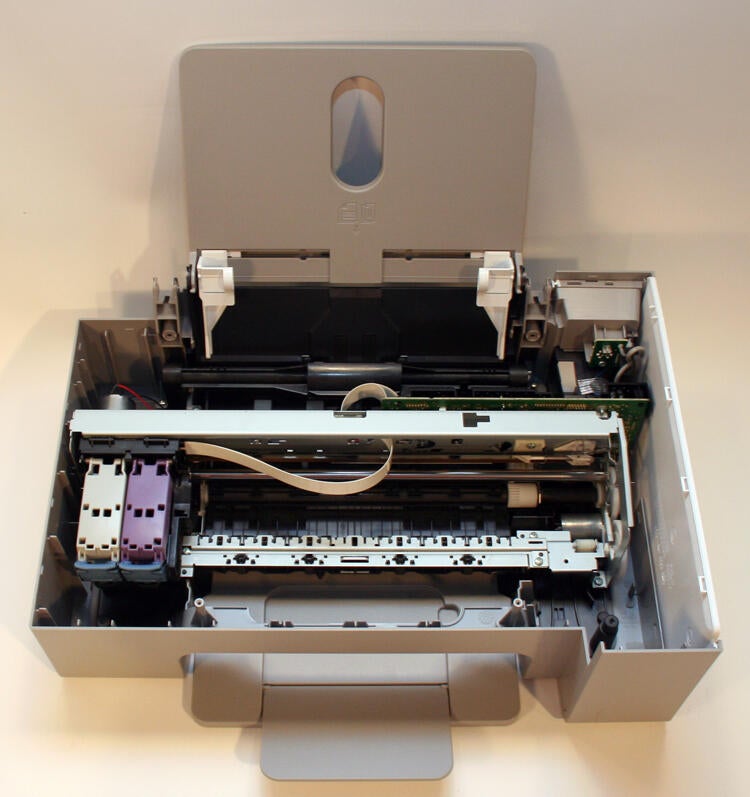
Here’s a look deep inside the inner workings of the Lexmark 2500 Series printer. With all the lids and dividing trays removed, you can see straight into the printer’s heart.
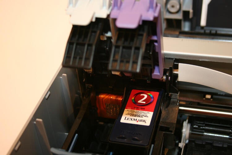
Looking inside the Lexmark 2500, here you see a close-up of the two bays that hold the black (empty on the left) and color (the bay on the right holding the #2) cartridges.
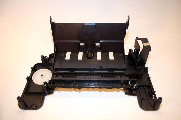
Another unheralded component, the paper supply tray fulfills a crucial responsibility (holding the printer’s paper and feeding it without jams into the printer’s inner workings).
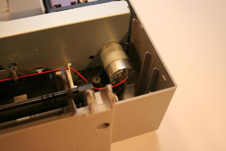
Here’s a close up view of the motor unit that powers the mechanism that guides the inkjet cartridges.
Here’s a view of the Lexmark 2500 Series printer shell. Removed from the rest of the printer assemblies, these few pieces of molded plastic provide a tight fit and finish for the 2500 printer.

With the printer’s outer shell casing stripped away, the rollers that advance paper within the printer become visible.
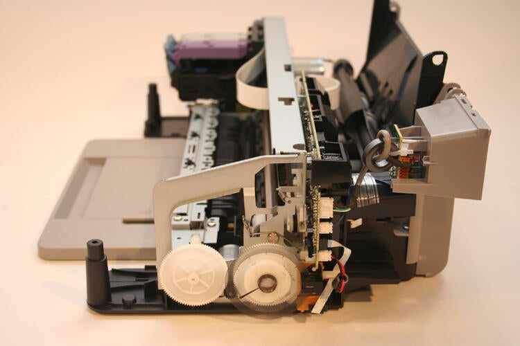
Viewing the printer assembly, without the shell casing attached, from the side reveals even more of the printer’s internals.
Here you can see the gears that power the paper rollers, as well as the end of the circuit board that controls the inkjet printing itself. Further, toward the top right corner you can see the data link for the USB port.
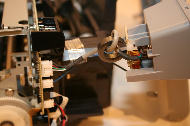
A close up view of the USB port shows cabling is wrapped around a metallic ring zip-tied to the printer’s casing.
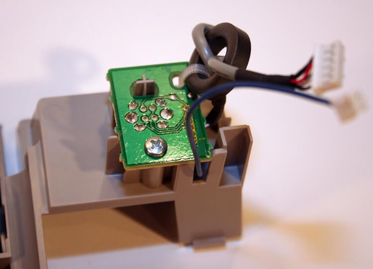
The USB port, disconnected and removed from the printer.
Here’s the paper tray, which holds printouts the printer produces, once its removed from the printer.
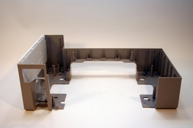
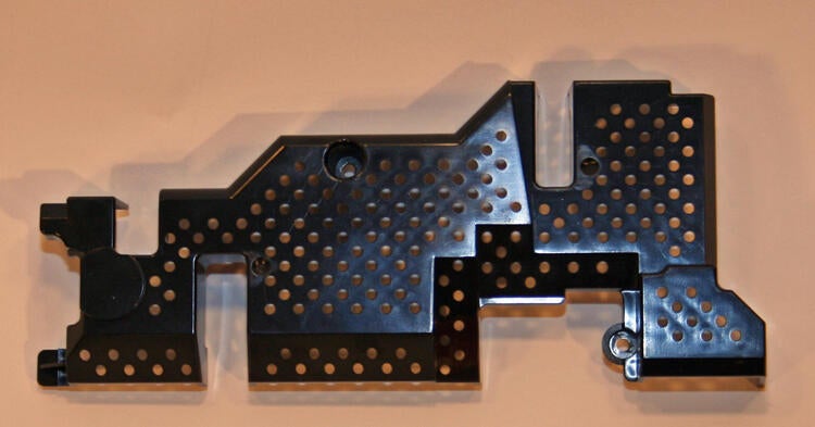
Here’s the main printer base used to house the 2500 Series’ internals. This black plastic assembly forms the skeletal foundation for the printer and houses the main printer components.
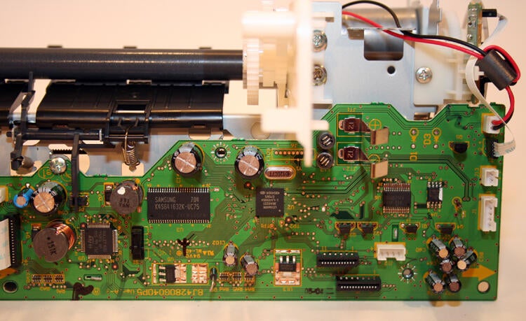
This Samsung-powered circuit board guides the inkjet cartridges whenever users request copies or prints.
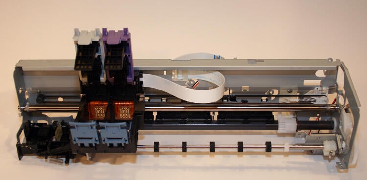
Once removed from the printer, the inkjet cartridge unit assembly appears fairly straightforward. Composed of a few guiderails, simple gears and printed circuit board, the simple design is capable of producing full-color photos, high-resolution printouts and even high-quality copies.
This plastic shield provides a protective cover for the printed circuit board that controls and manages the printer’s inkjet cartridges and actual printing process.
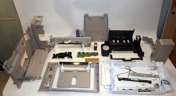
Completely disassembled, the Lexmark 2500 printer’s components sprawl across a decent-sized table.
View Erik Eckel’s Right Tool gallery review of the Lexmark 2500 All-In-One here.

Erik Eckel is a managing partner at Louisville Geek and president of Eckel Media Corp. He previously served as Executive Editor at TechRepublic. He received Microsoft Engineer accreditation from Sullivan University and earned his Bachelor's Degree in English from the University of Louisville. He's earned Network+, Windows NT 4.0 MCP+I and MCSE, and Windows 2000 Professional MCP accreditations.


