By John Lee
Does Jar Jar Binks always invite himself over to your house to watch Top Chef? Do Ewoks keep rummaging through your trash? Darth Vader’s Lightsaber from Master Replicas might be able to help out with these issues.
But what exactly is inside this elegant weapon of a more civilized age? Let’s see how Master Replicas’ craftsmen were able to reverse-engineer this piece of Jedi technology.
Many collectors of sci-fi toys and memorabilia often value an item’s packaging as much as the goodies it contains. No one will find it easy to throw out this handsome box anytime soon.
On the bottom of the box, we get a subtle, yet stern, reminder of who exactly this lightsaber belongs to.
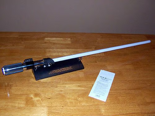
Though not mentioned on the packaging, the lightsaber comes fully assembled with an elegant display stand and a pamphlet of instructions and safety precautions. Remember, kids: It’s all fun and games until someone loses a hand!
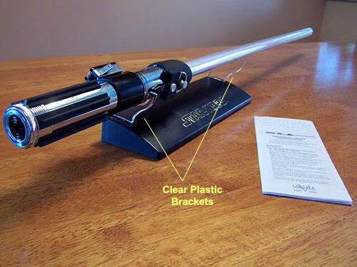
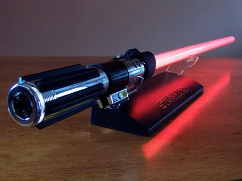
Although the base of the display stand is black, the brackets that hold the saber itself are clear plastic, allowing for an unobstructed view of the hardware as possible.
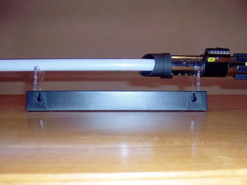
The back of the display stand reveals yet another unpromoted bonus: the stand is wall-mountable!
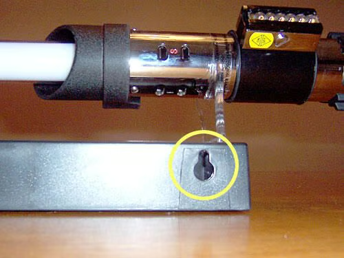
A close-up of the back of the display stand shows us that all it takes to mount the lightsaber on the wall is a couple of heavy-duty screws and anchors that the two slots can hang off of.
Inspecting the top of the handle, we can see that the sturdy polycarbonate blade is firmly attached and there is no danger of it sliding out without anything but the heaviest wear and tear.
\r\nExacting details of ILM’s handiwork are duplicated down to the esoteric numbers and letters inscribed on the handle. Safety notices are posted on a clear, removable label.
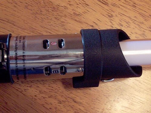
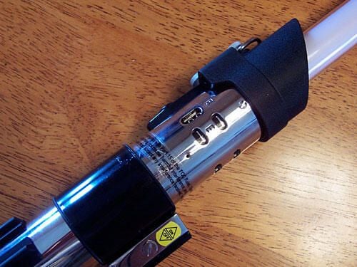
Midway down the handle, we find the power switch, complete with a pin and latch that seem to serve no real function.
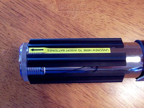
The last half of the handle is the hilt, which features a label that instructs the user on how to exchange three “AA” batteries that serve as the power source.
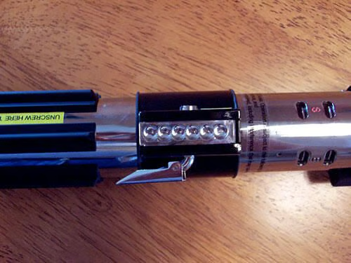
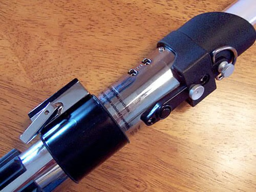
Turning the saber over, we find more design characteristics (belt loop near the blade, two silver control studs) that tells the hard-core Star Wars fan this could only be Darth Vader’s lightsaber.
Here’s more of the attention to detail that we’ve come to expect from licensors of Star Wars. Note that the power switch is labeled with a removable ON/OFF sticker.
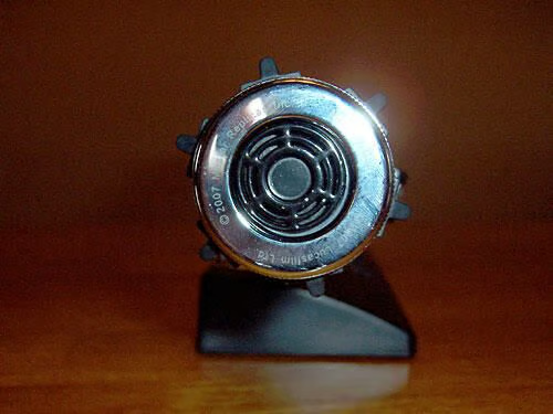
Like the rest of the handle, no expense was spared in crafting the pommel.
Although it was too quick to photograph, turning the saber on activates the red lights in the blade in stages from bottom to top, giving the same ignition and effect as in the movies.\r\n
\r\nNaturally, turning the saber off causes the lights to extinguish in sequence from top to bottom as well.
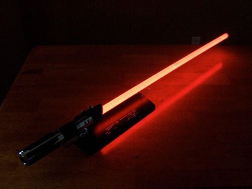
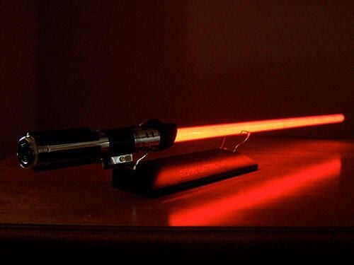
In the dark, the blade gives off a bright and healthy glow.
The sound chip inside the handle plays the familiar humming effects from the movies when the blade is activated. Waving the lightsaber also yields those other well-known sound effects.\r\n
\r\nAnd although the instruction and safety pamphlet advises against it, lightly striking a sturdy object with the blade makes the handle give off that famous “clashing” sound you hear when two lightsabers meet in combat.
Oooh! Ahhh!
Time to start breaking this lightsaber down.\r\n
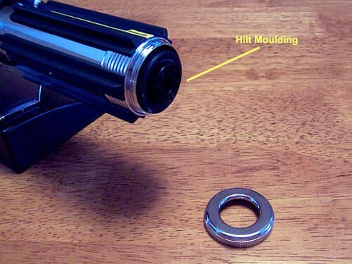
\r\nThe ring of the pommel unscrews easily enough, revealing that the black moulding of the pommel is there for more than just looks; it actually houses the batteries that power the lightsaber! A nice touch.
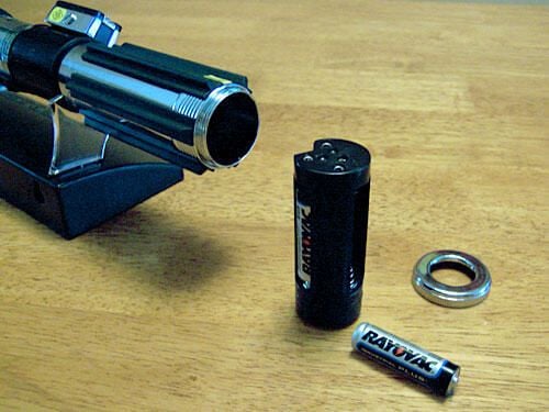
The removed battery supply shows a cylindrical housing that holds three “AA” batteries.
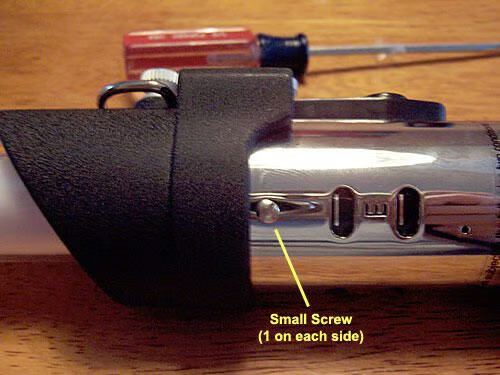
With the batteries out, these two small screws on opposite sides of the top of the handle are the most obvious place to start cracking open the saber.
Removing the two small screws yields absolutely nothing, so I turn the handle over, looking for more obvious things to take out.\r\n
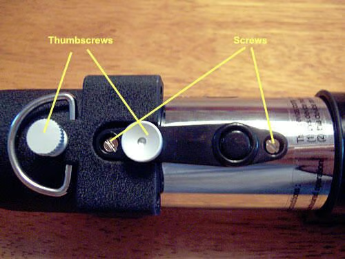
\r\nHere I find not only a couple of more open screws on the black guard strip that holds three non-functioning switches, but I also discover that the two silver control studs are actually thumbscrews! Neat!
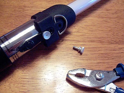
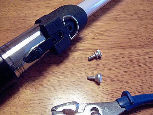
The exposed screws coax out easily enough, but I need the help of some pliers to take out the top thumbscrew/control stud.
The bottom thumbscrew/control stud is no easier to unseat.
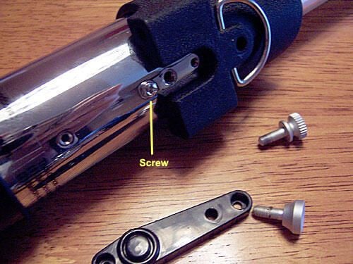
Once the guard strip is out, yet another Philips-head screw is revealed.
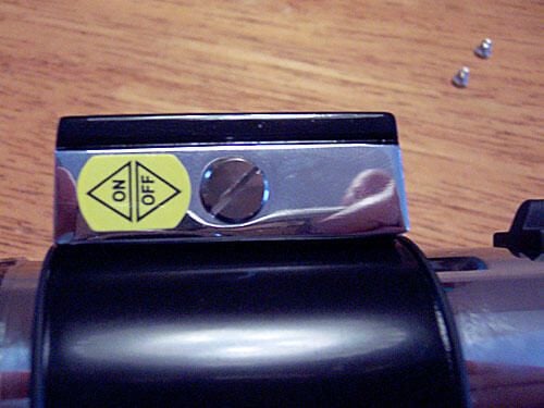
Despite all of the hidden screws I’ve removed, the handle is still tight as a drum. I turn the handle over to see a rather obvious flathead screw that I overlooked on the side of the power switch.
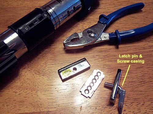
The large flathead screw comes out of the power switch easily, but latch pin and screw casing requires a bit of effort with the pliers.\r\n
\r\nOnce the pin is pulled out, the power switch falls apart into three pieces.
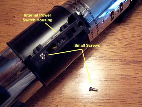
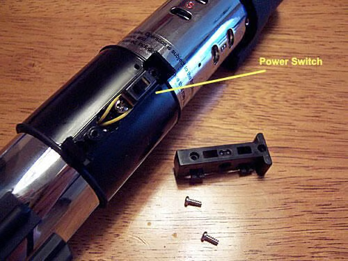
With the external power switch undone, I find a secondary power switch housing underneath. I remove it by taking out two more small screws.
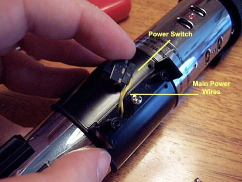
Now that the secondary power switch casing is off, I find the actual power switch itself — it is quite small and fragile.
The power switch proper is held to the handle with a small amount of a rather weak adhesive and pulls off easily.\r\n
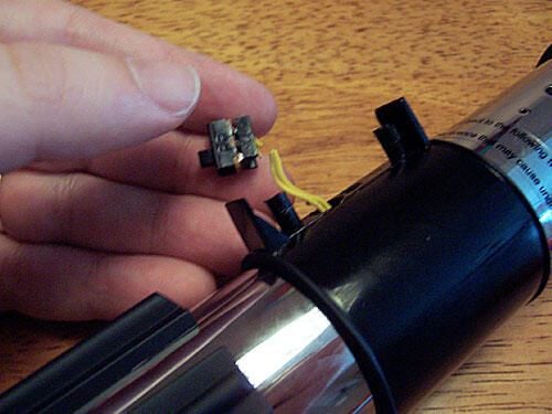
\r\nHowever, the main wires that run to the switch are connected to circuitry inside the handle, and I can’t fit the power switch through the small opening in the handle!
With my editor’s permission, I cut the power wires from the switch in order to continue with the disassembly.\r\n
\r\nIt will take someone with soldering skills to get this baby working again. (Sigh…)
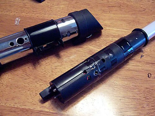
With a little muscle, I extract the blade and its electronic components from the handle.\r\n
\r\nI’m a little surprised to find that the functioning electronics take up only 1/3 of the length of the handle!
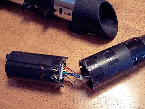
The electronic casing seems to be held together with Scotch tape, so it proves easy to break it in half.
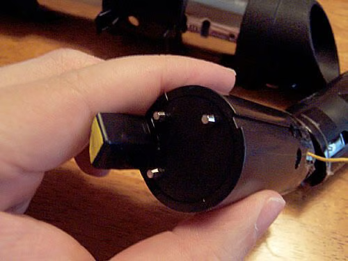
The bottom half of the casing shows the connectors to the battery pack.
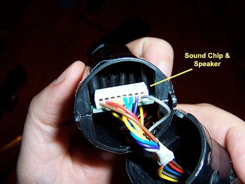
Try as I might, I can’t get the sound card and speaker components unseated from the bottom half of the electronics housing, which has been super-glued together, so I opt for this voyeuristic shot.
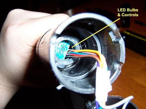
The top half of the cylindrical electronics housing holds the LED bulbs and circuitry.
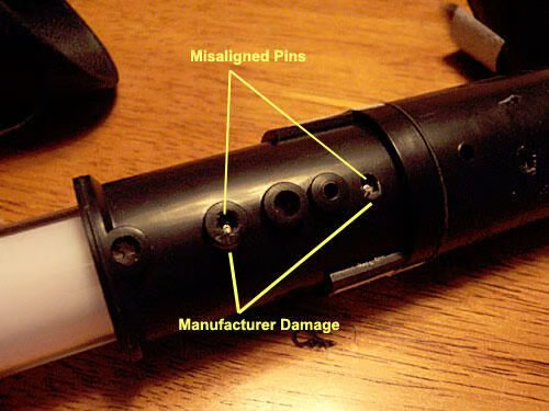
What’s this? In order to open the top half of the casing to get to the LED innards, I need to remove these two pins.\r\n
\r\nBut it’s obvious by the position of the nearly-hidden pins in their sockets – and the distress to the outer edges of the sockets themselves – that the manufacturer misaligned the pins in their sockets during the assembly process.\r\n
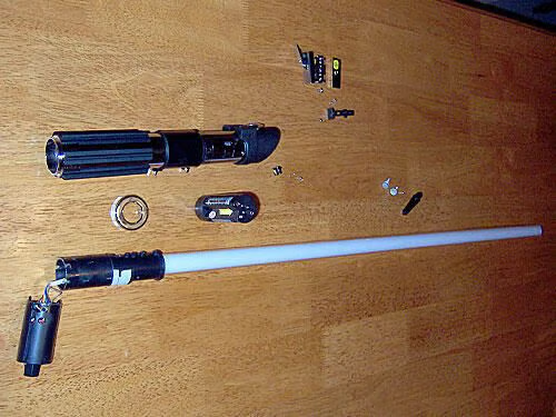
\r\nIt’s pretty clear that I would need a hacksaw to go any further, and could possibly end up cracking the blade, so my editor agrees that this is a good stopping point.
Not a whole lot to it, is there? Master Replicas wisely kept it simple.
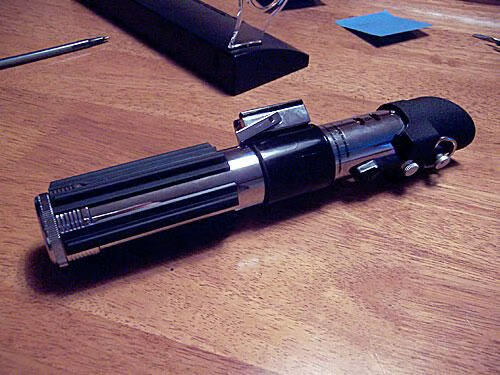
Although the blade no longer functions, I am able to put the handle back together, which should come in handy for costume parties and while camping outside theaters waiting for the next Star Wars movie — you know there’ll be one!
\r\nJohn Lee is a consultant specializing in design and illustration and a freelance technical writer. You can visit his Web site at johnleestudio.com.