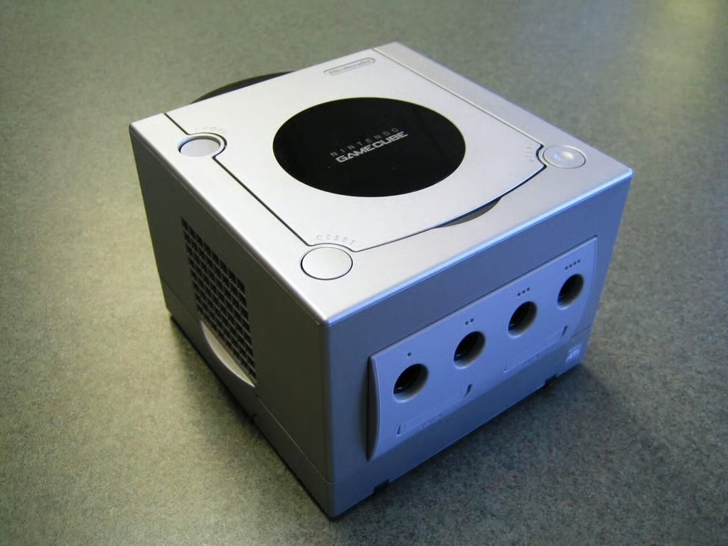
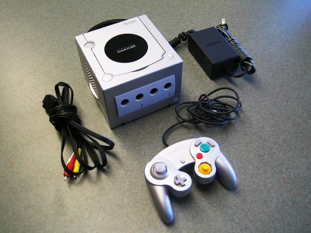
\n\tReleased in 2001, the GameCube was Nintendo’s fourth video game console and a significant step forward. With the GameCube, Nintendo moved away a from cartridge-based games to 1.5GB 8cm discs–similar to miniDVD.
\n\t
\n\tOriginally priced at $199 USD, we purchased this refurbished unit for about $70.
\n
\n\t\n\n
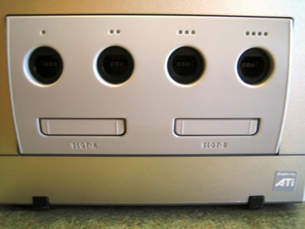
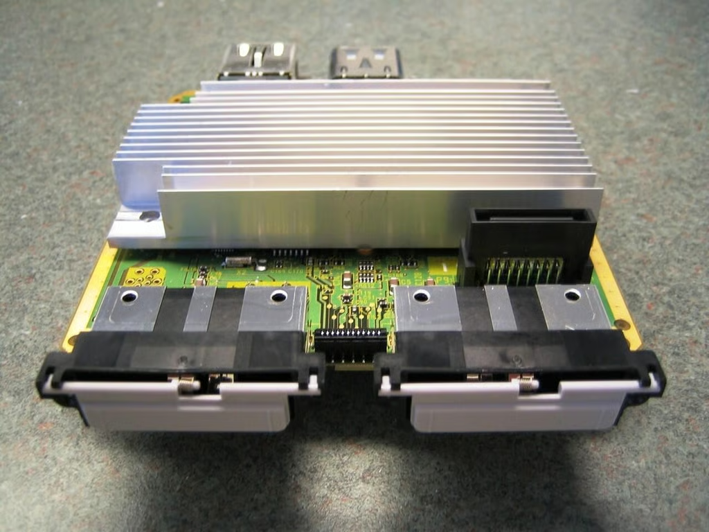
The four controller ports and two memory card slots are located on the GameCube’s front panel.
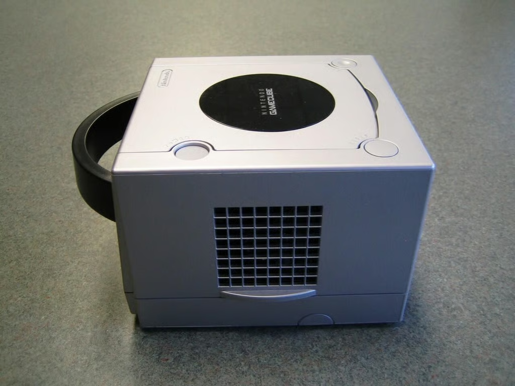
The GameCube’s air intake is located on the unit’s right side.
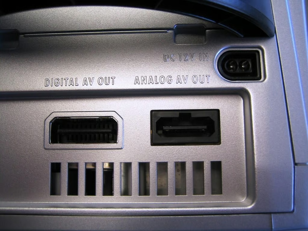
The GameCube has one analog audio/video output and one “Digital” video output–this output was removed in later versions of the GameCube.
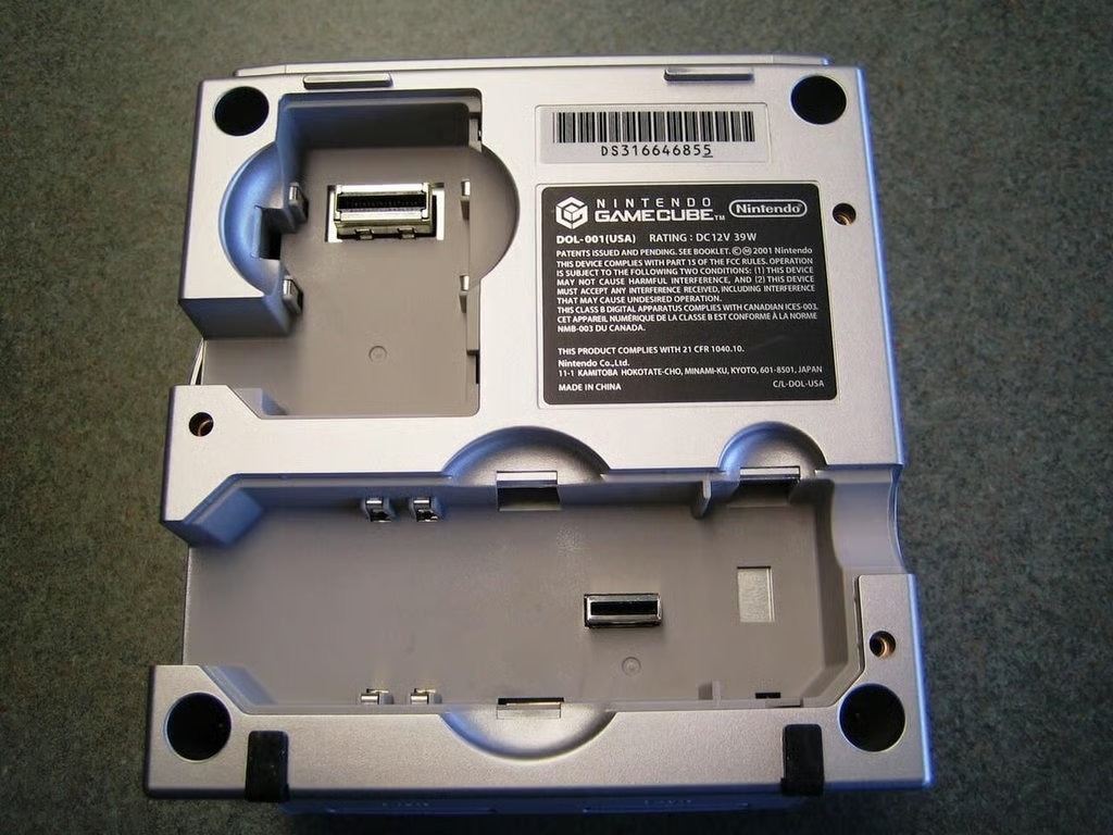
The GameCube has a highspeed data port and serial port.
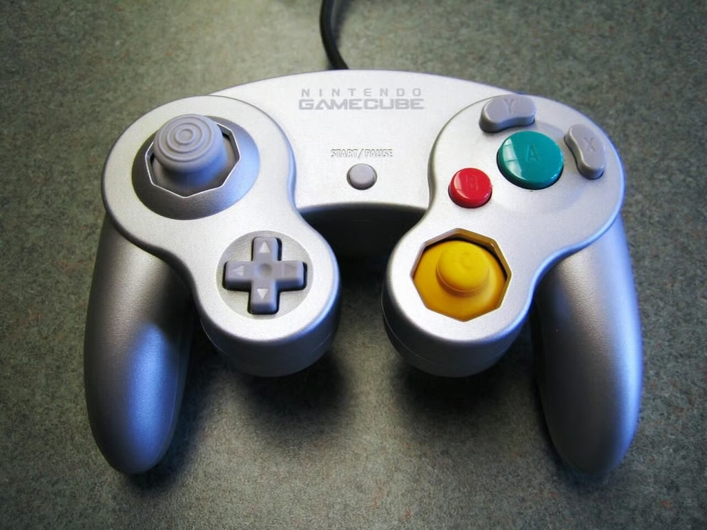
The GameCube controller has two analog sticks, a D-pad and eight buttons.
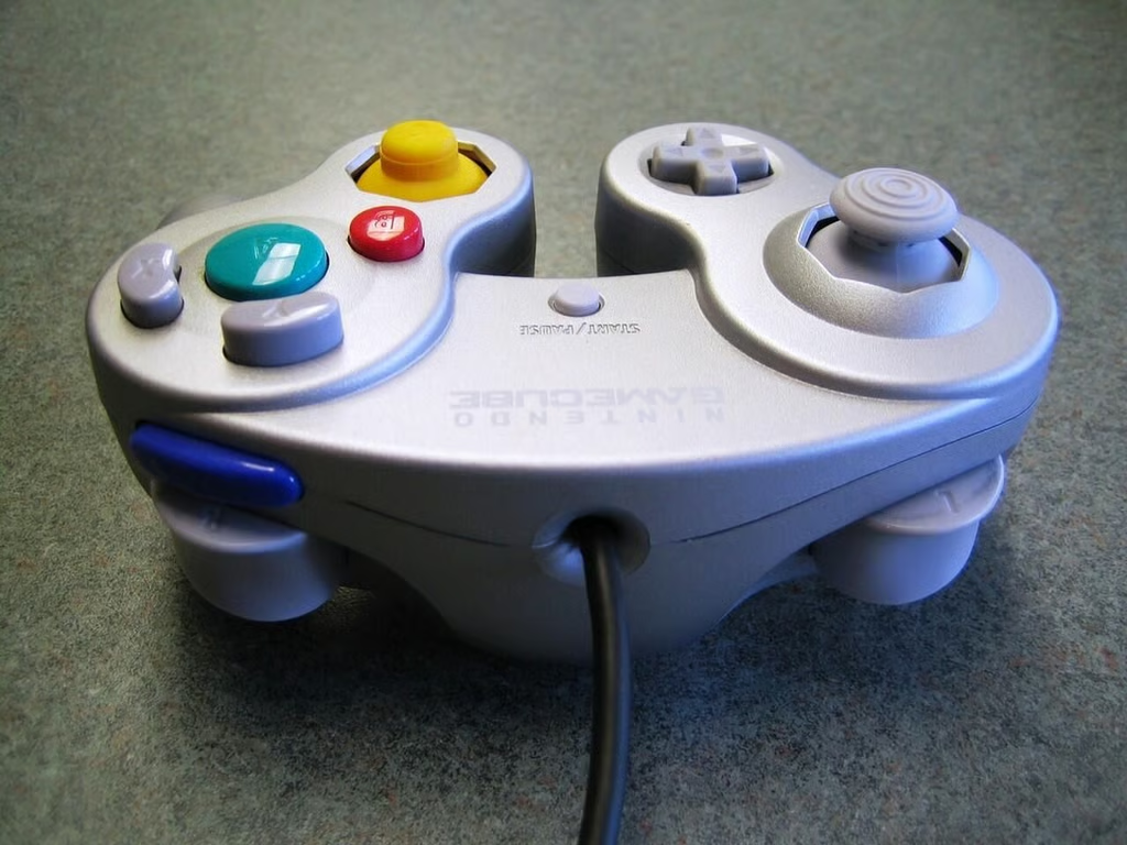
Two trigger buttons and a shoulder button are located on the front of the controller.
Disassembling the GameCube begins by removing the four tamper resistant screws that hold on the top cover.
These screws use a 6-point, external star head. You can buy specialty screwdrivers and bits online, but I didn’t have that much time. I used a drill. this damaged the four cover posts on the GameCube’s chassis, but it doesn’t really matter. I don’t plan on moving this GameCube around much and with the top cover in place, the unit works fine.
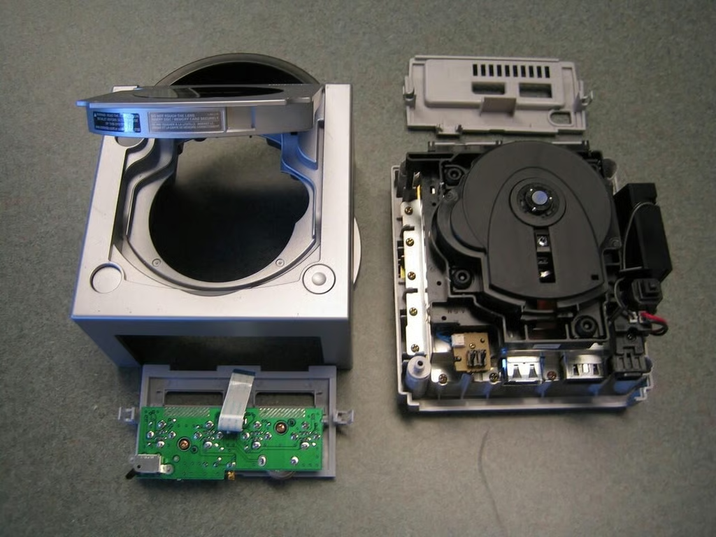
With the four screws removed, you can lift off the top cover and the snap off the back and front panels.
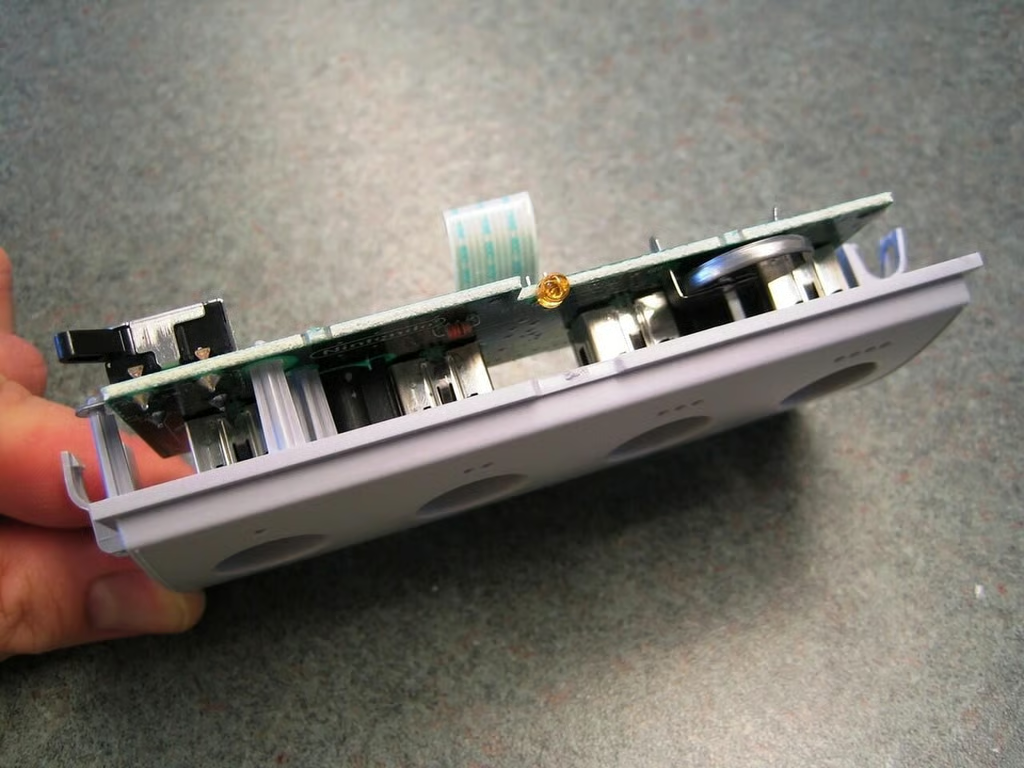
The front panel snaps to the chassis. It contains the four controller ports and slot for the two memory card ports.
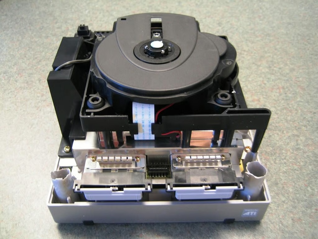
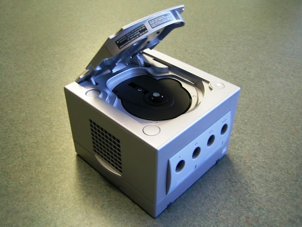
The GameCube’s optical drive sits atop the chassis.
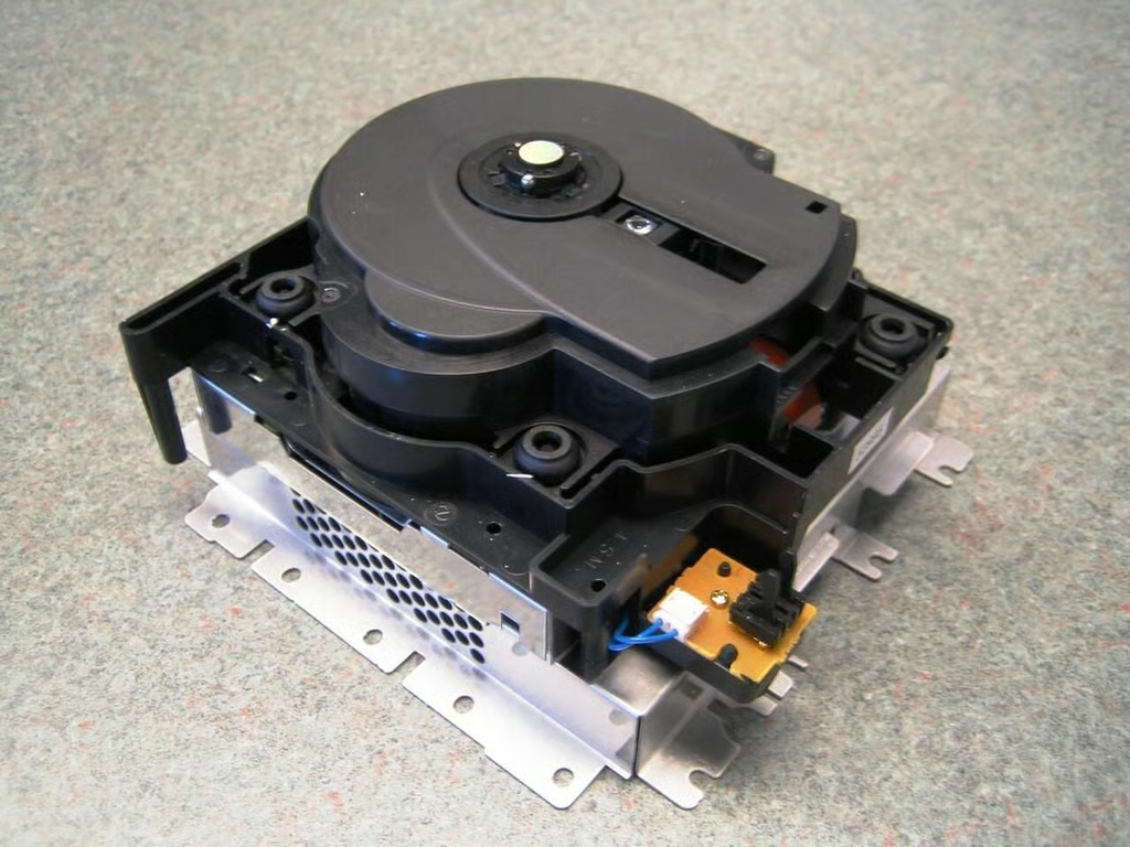
With the fan removed, you can access and unscrew the remaining Phillips screws that hold the optical drive to the chassis.
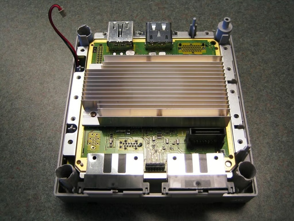
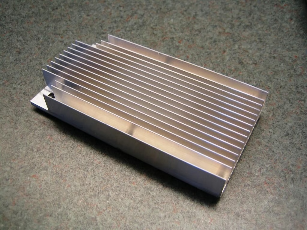
With the optical drive gone, we get our first look at the motherboard. The large heatsink covers most of the GameCubes chips.
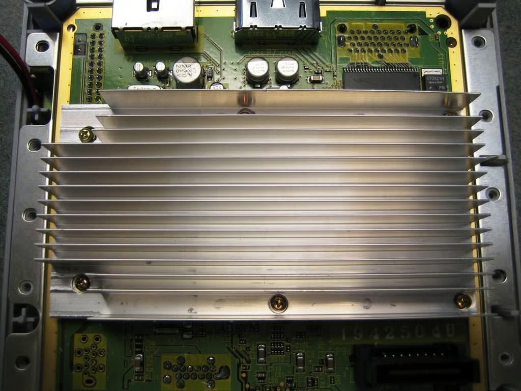
Six Phillips screws hold the heatsink to the motherboard.
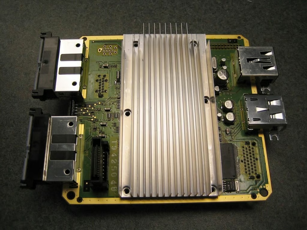
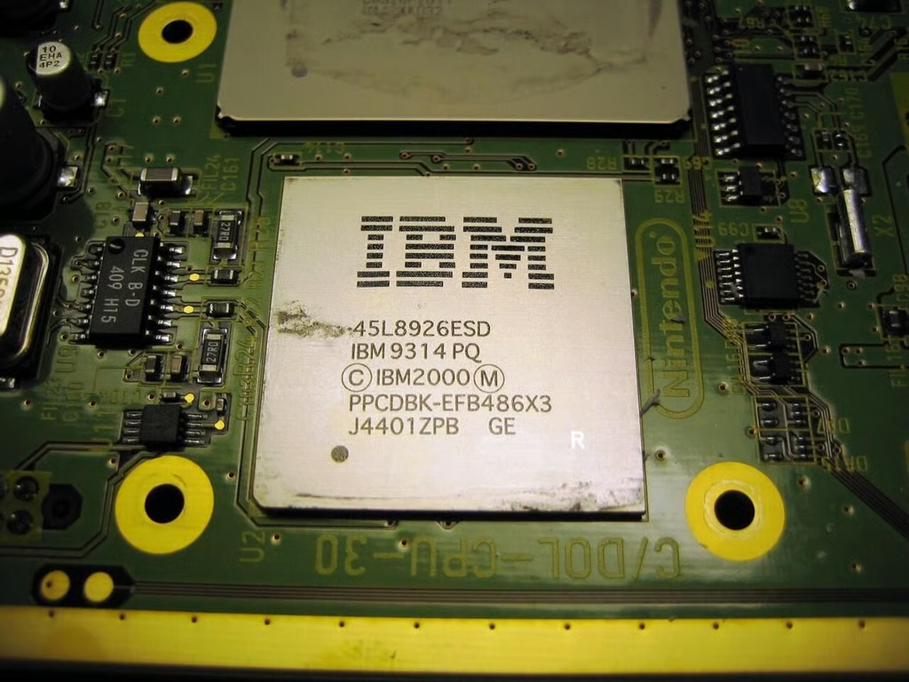
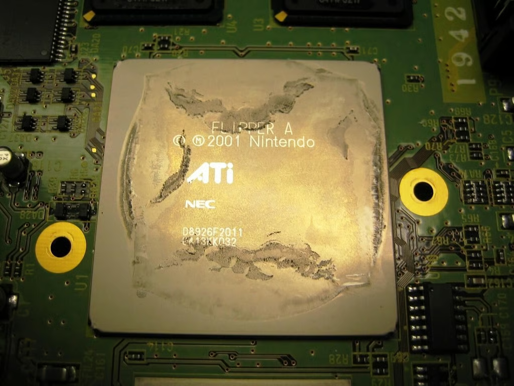
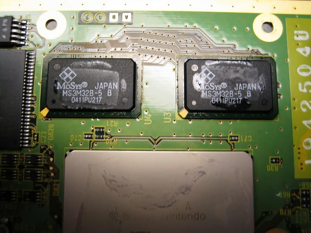
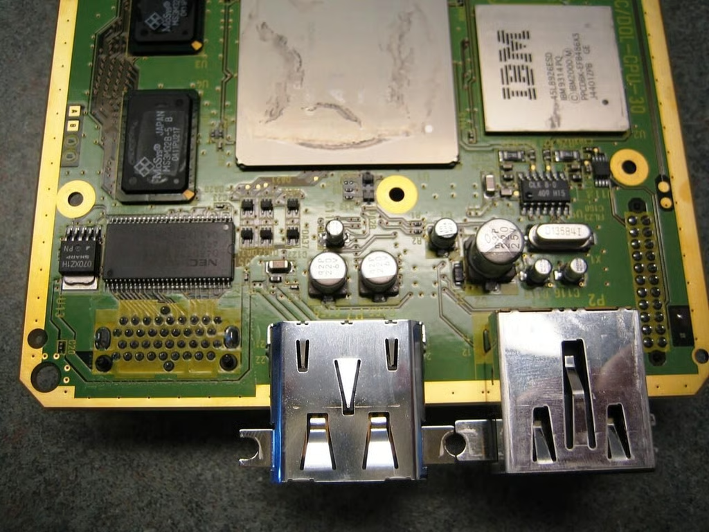
With the screws removed, I can gently remove the heatsink and expose the CPU, GPU and the GameCube’s two 1T-SRAM memory chips.
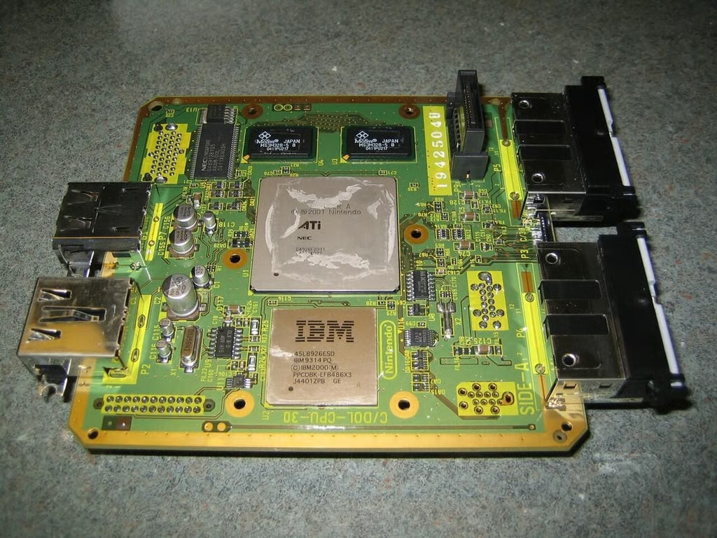
After removing the heatsink, we can see the CPU, GPU, and two 1T-SRAM memory chips.
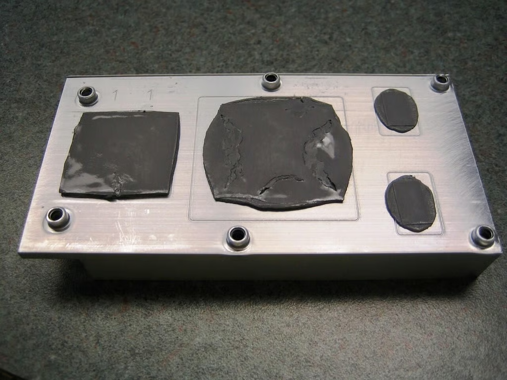
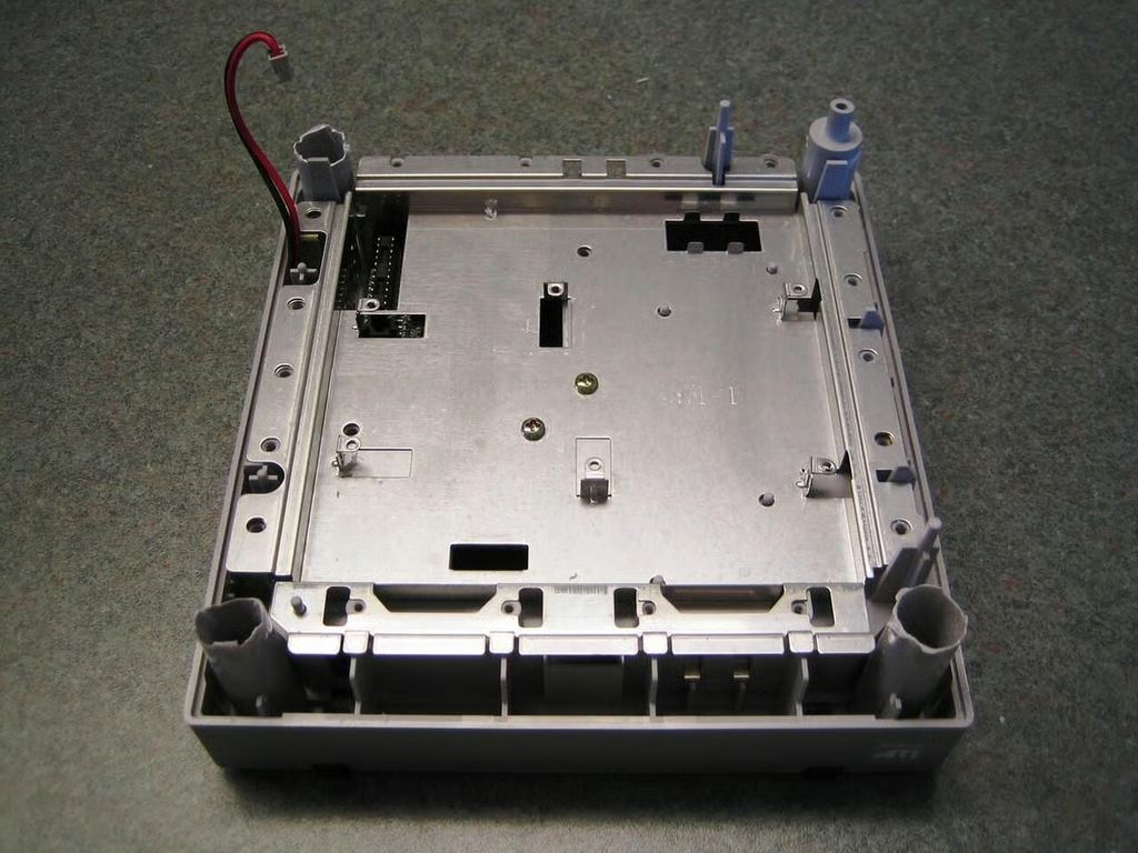
The metal base plate is secured with two Phillips screws.
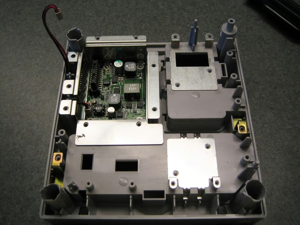
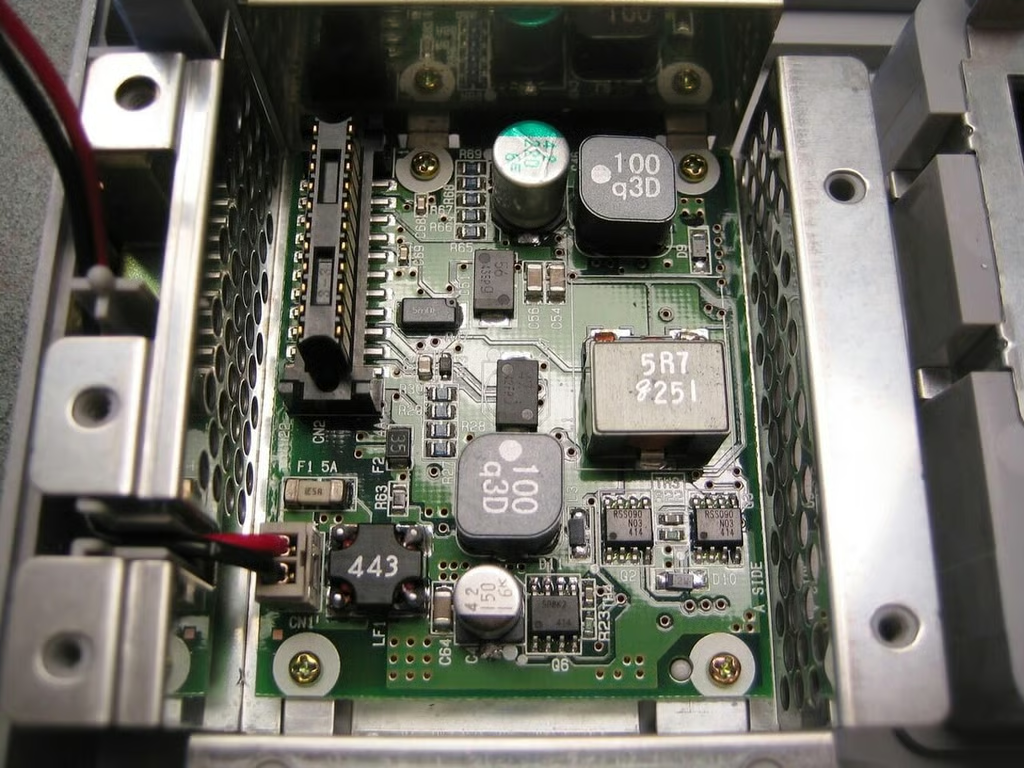
With the metal base plate removed, we can see the GameCube second PCB.
Bill Detwiler is the Editor for Technical Content and Ecosystem at Celonis. He is the former Editor in Chief of TechRepublic and previous host of TechRepublic's Dynamic Developer podcast and Cracking Open, CNET and TechRepublic's popular online show. Previously, Bill was an IT manager in the social research and energy industries. He has bachelor's and master's degrees from the University of Louisville, where he has also lectured on computer crime and crime prevention.


