\n\tAfter a week of trying, I finally got my hands on a Nintendo Wii. After taking it for a test drive, I began the painstaking and somewhat frustrating disassembly process. Come along as we go inside the Wii and see the hardware that makes Nintendo’s console tick.
\n
\n\t\n\n
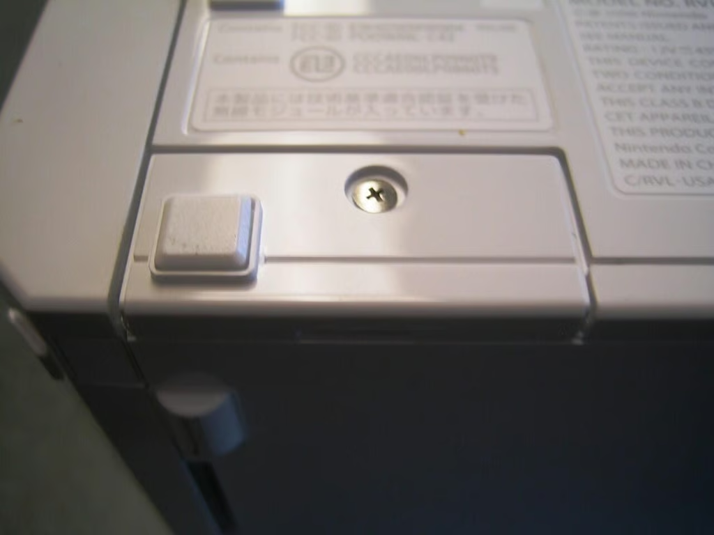
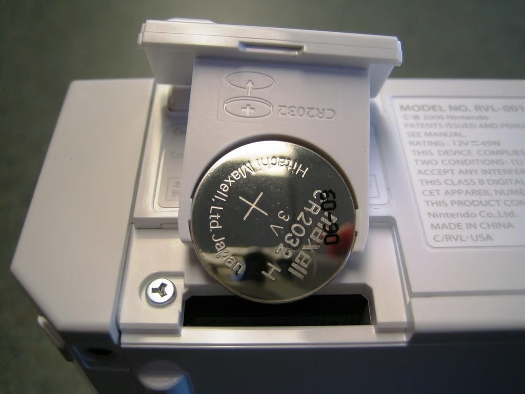
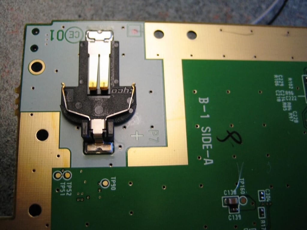
I started by removing the Wii’s system battery. This would be the first on many,. many screws.
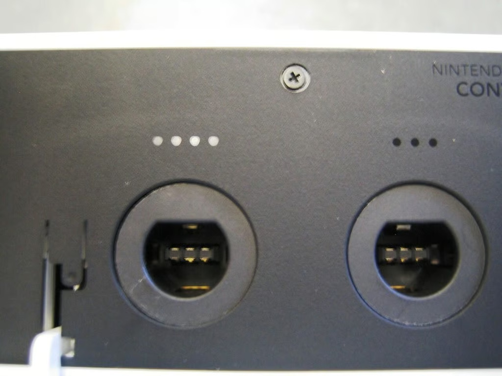
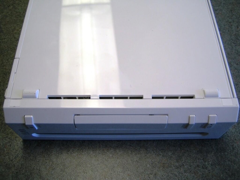
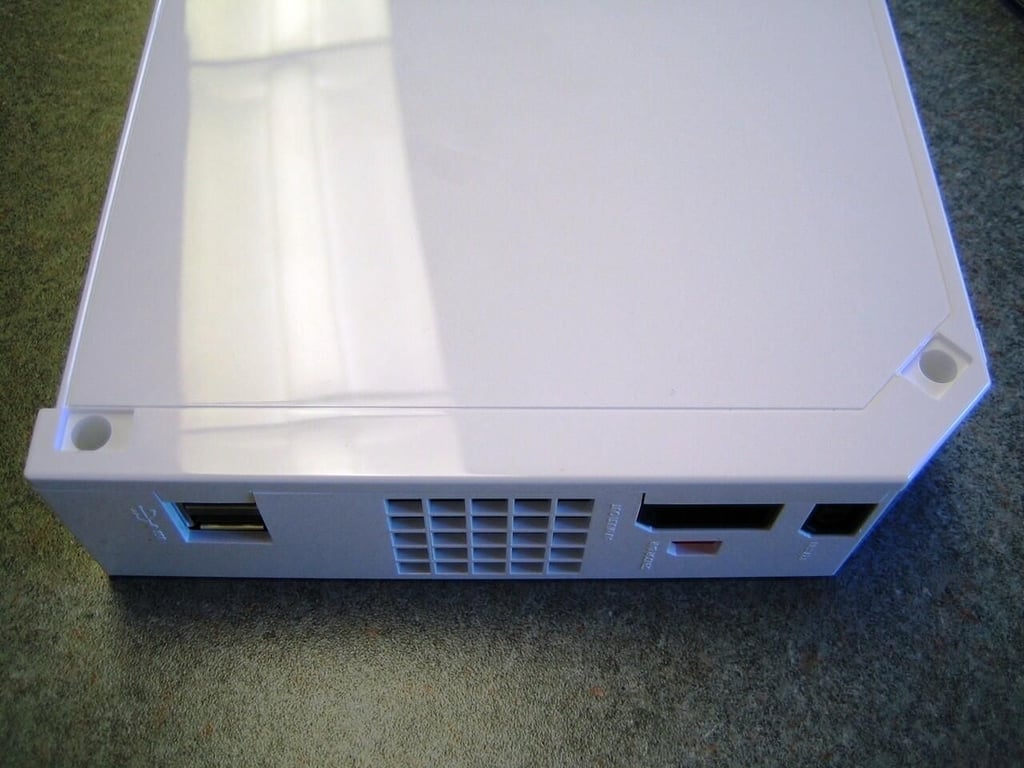
Next I moved to the black cover that surrounds the GameCube controller and memory card ports.
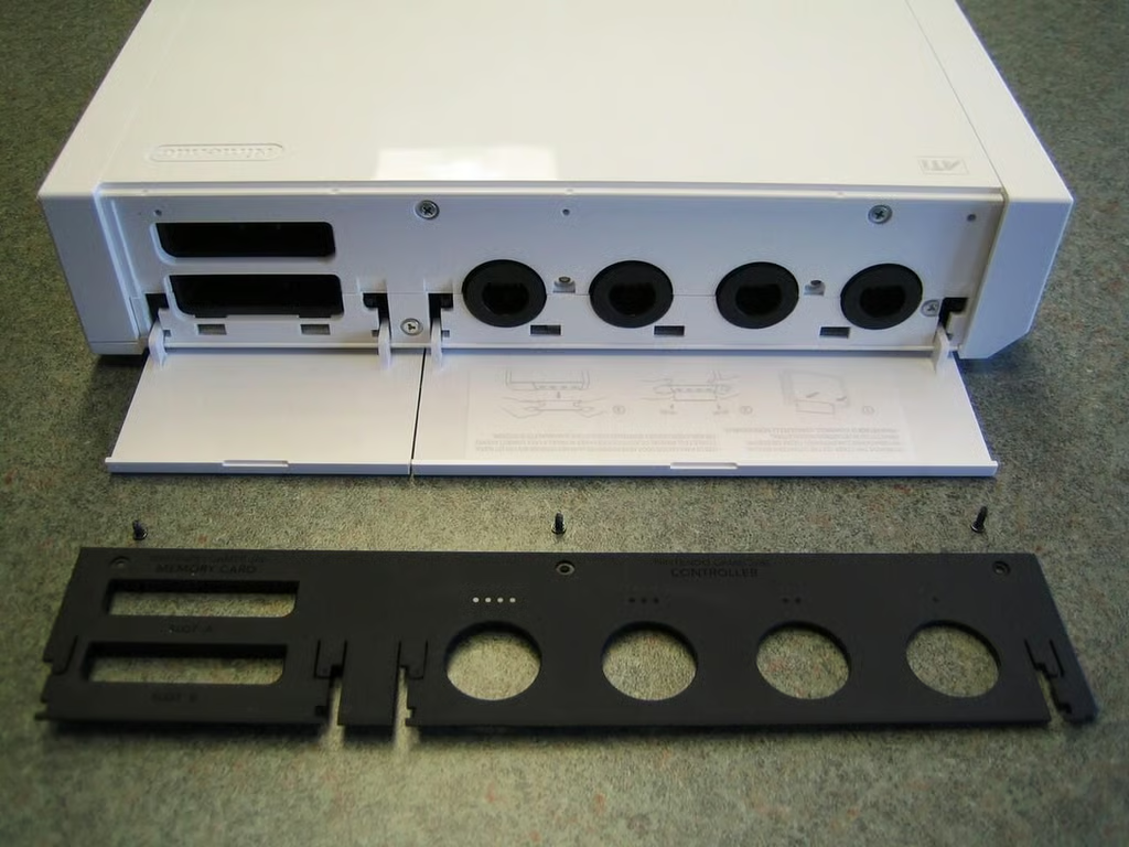
Three small Phillips screws hold the Wii’s black GameCube controller and memory card port cover.
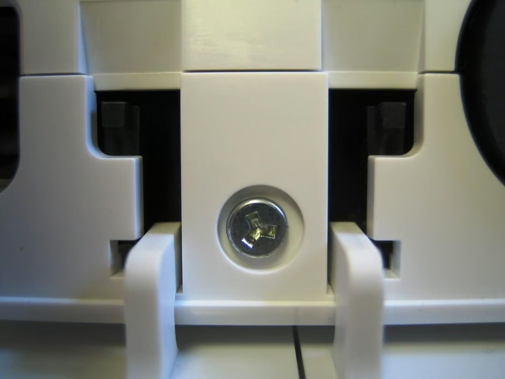
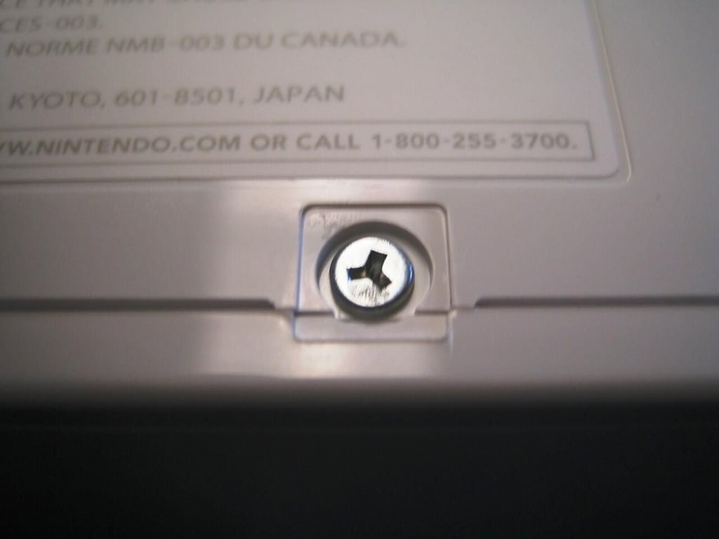
After removing the black GameCube port cover, I hit my first roadblock–triwing screws. Some argue that triwing screws make the manufacturing process easier, but these annoying fasteners are also designed to discourage people from doing exactly what I’m about to do–take this thing apart. Nintendo also uses triwing screws on the GameBoy Advance, GameBoy Advance SP, GameBoy Color, Nintendo DS, and GameCube controllers.
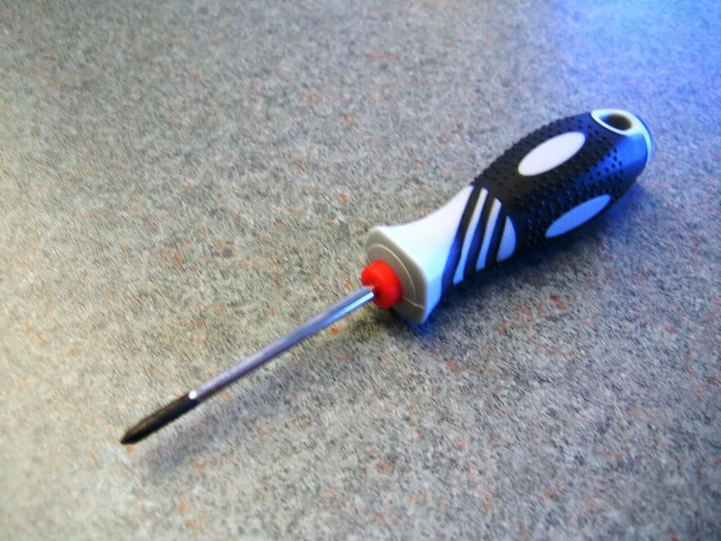
You’ll need a
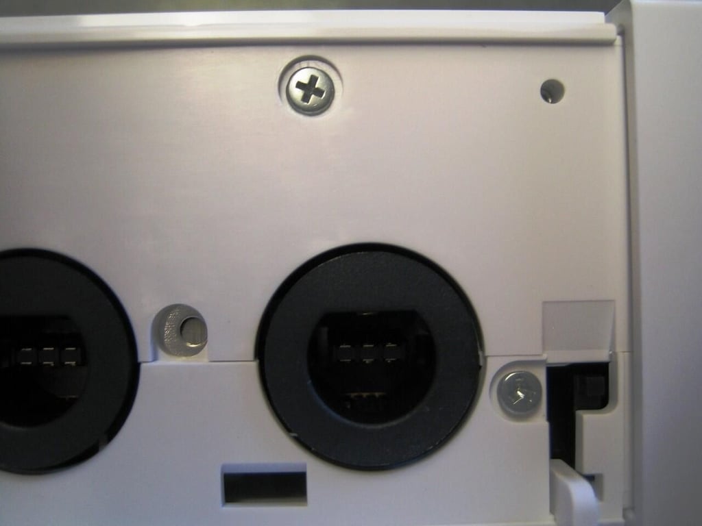
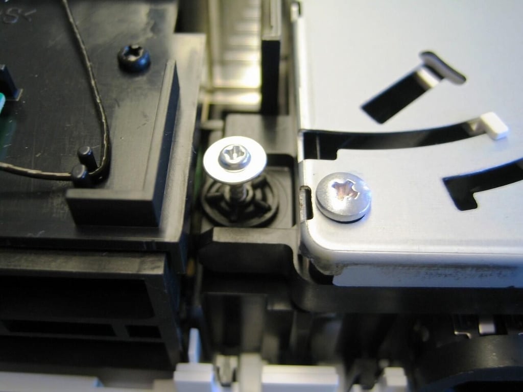
Once you remove the black GameCube port cover, you’ll find a mix of triwing and Phillips screws that should be removed.
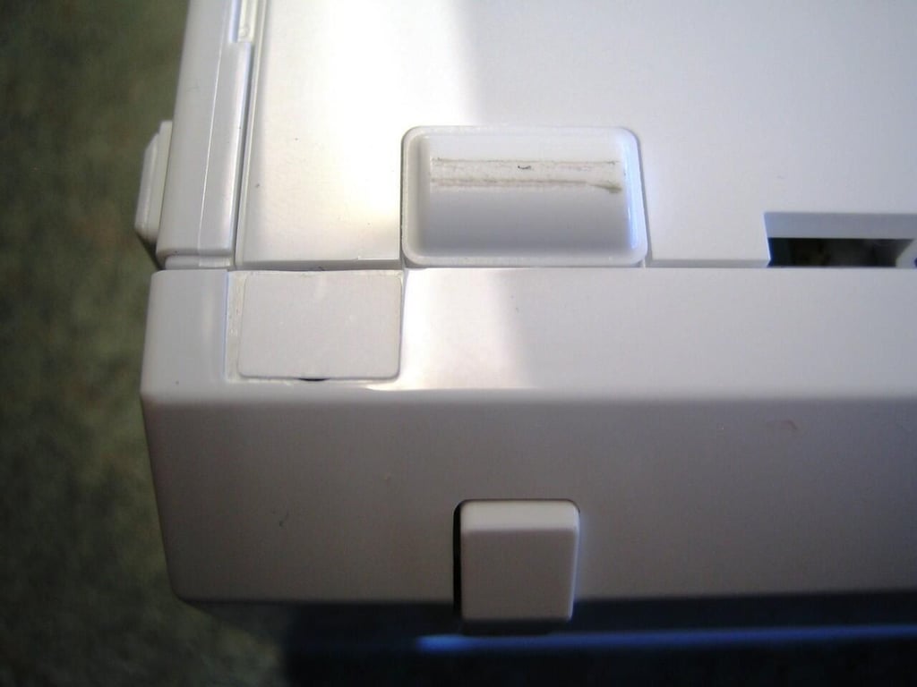
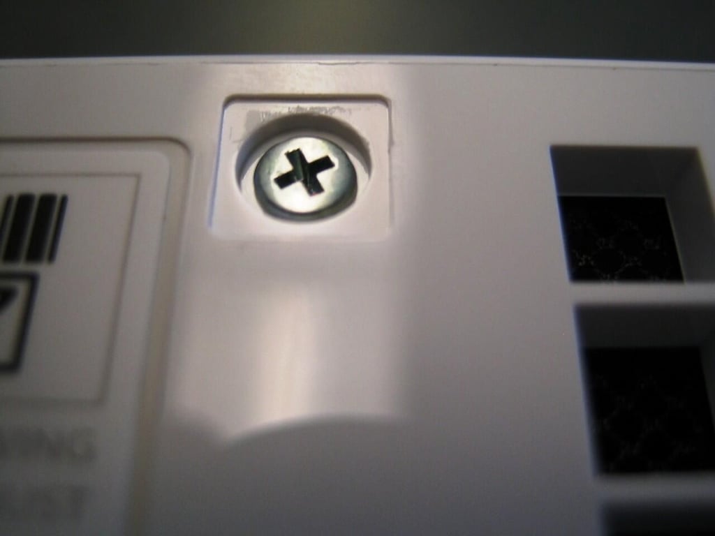
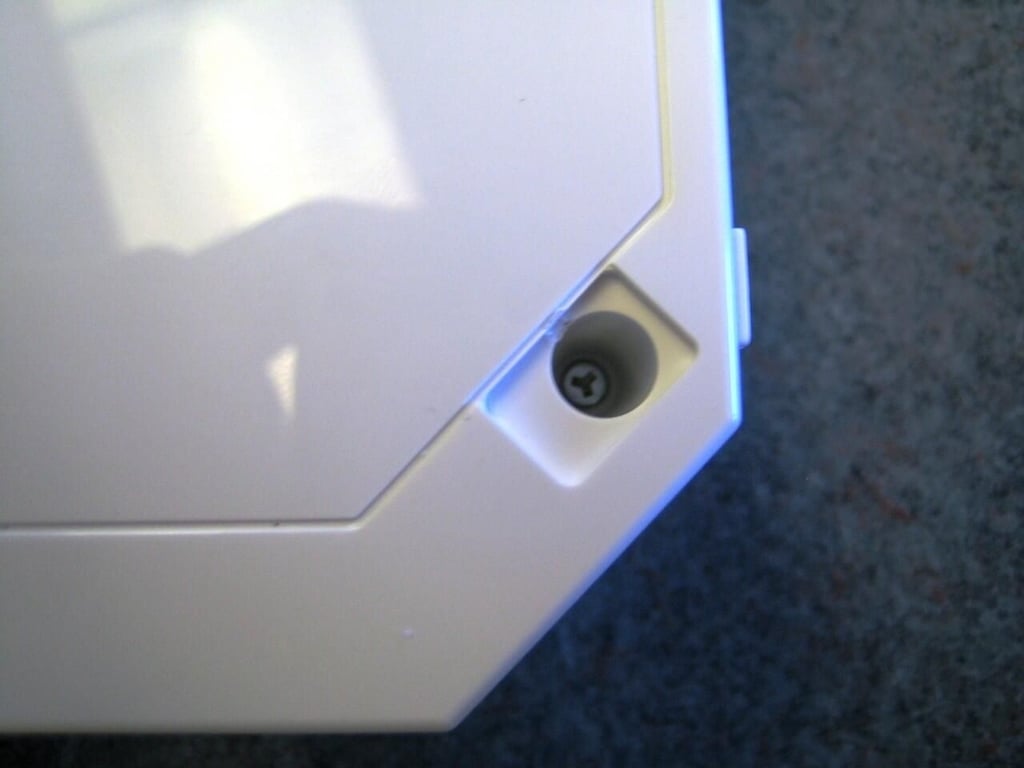
Several screws are hidden under white stickers, like the two under the Wii’s front face plate.
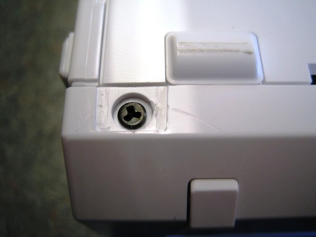
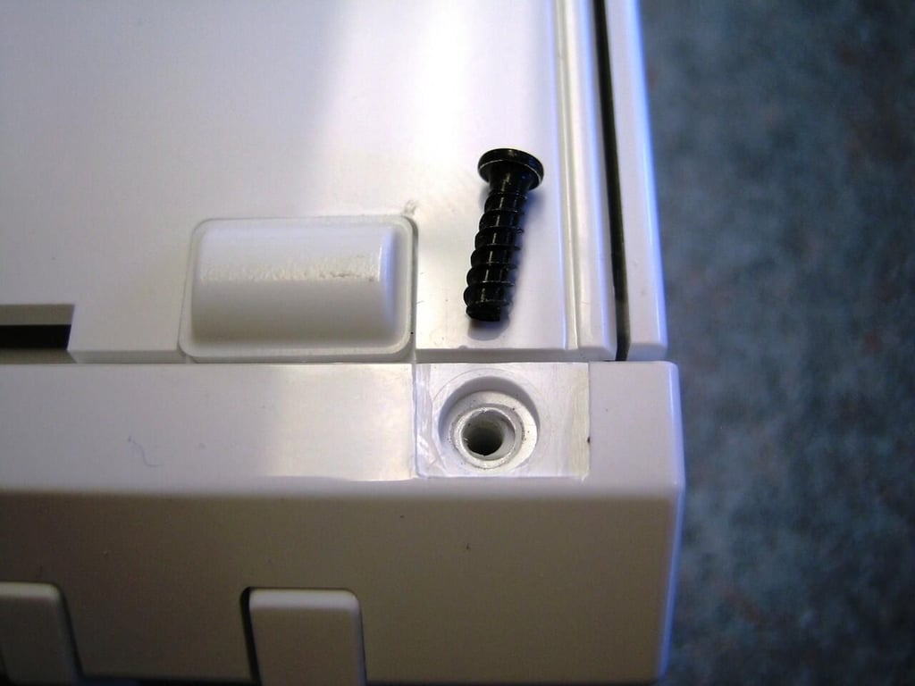
Removing the sticker reveals one of the triwing screws, that secure the Wii’s front panel.
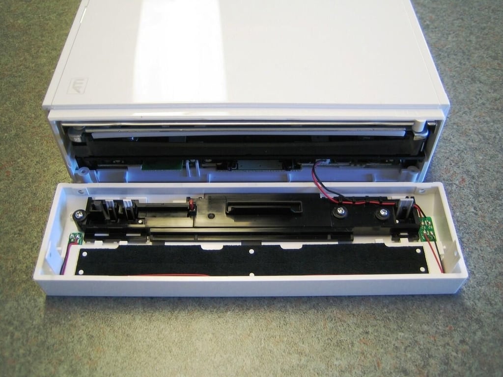
With the side and face plate screws removed, you can gently detach the face plate from the Wii.
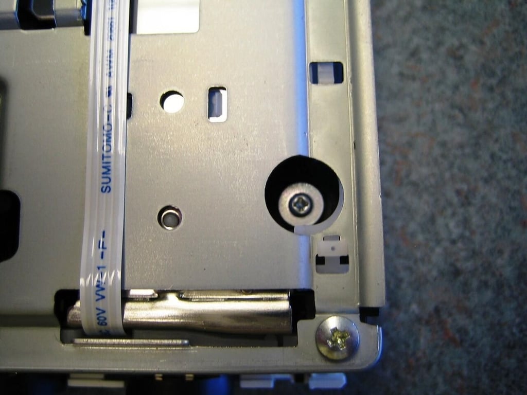
With the face plate removed, you can remove the remaining two triwing screws that secure the wii’s plastic case. these are found under the two rubber pads near the back of the Wii’s bottom shell.
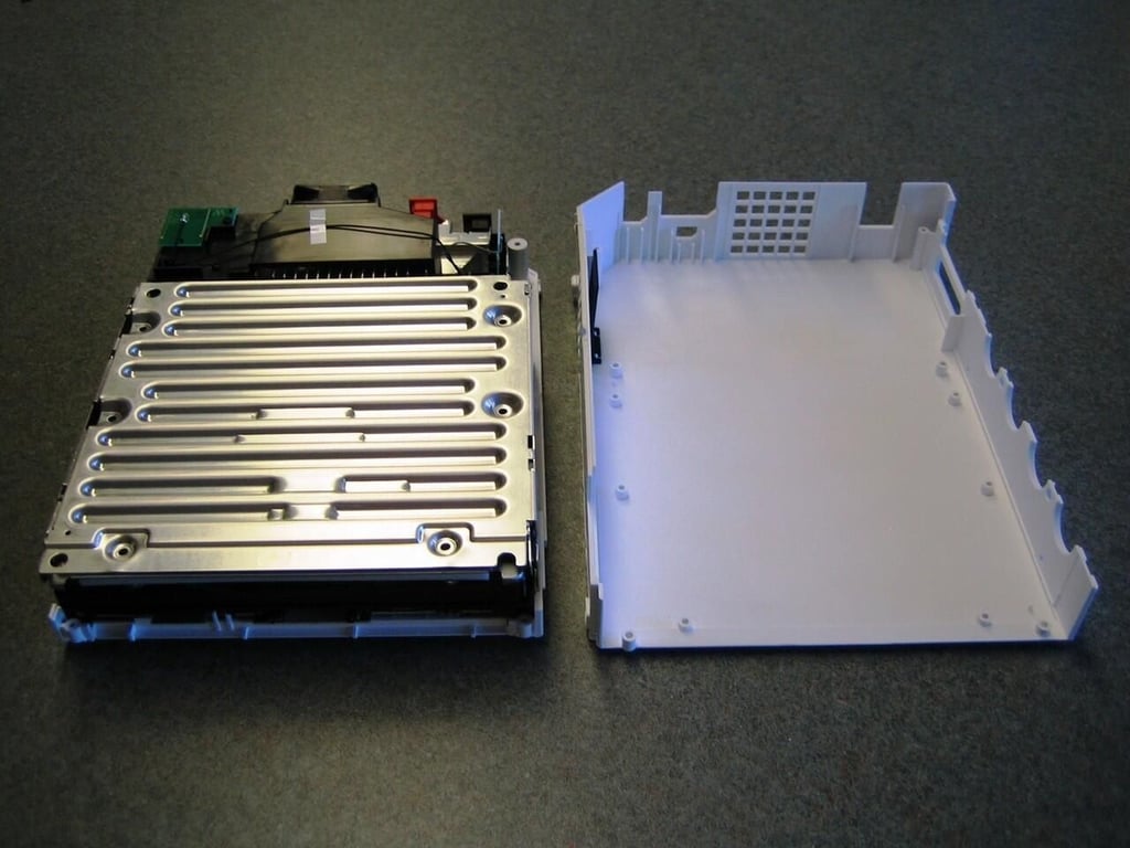
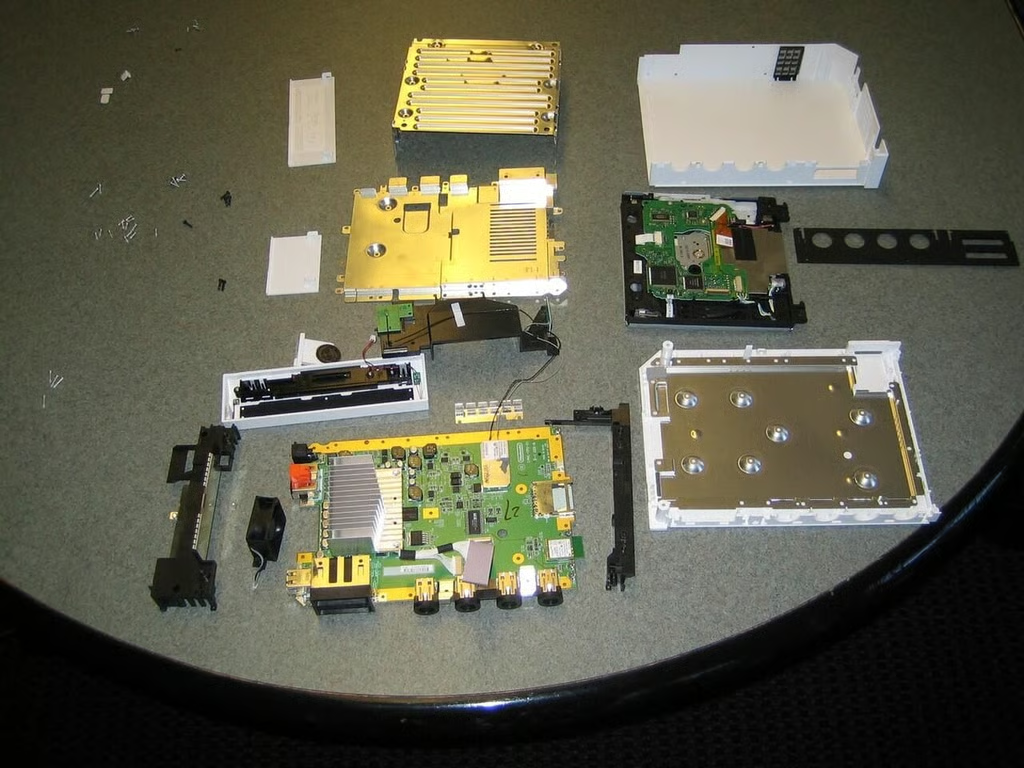
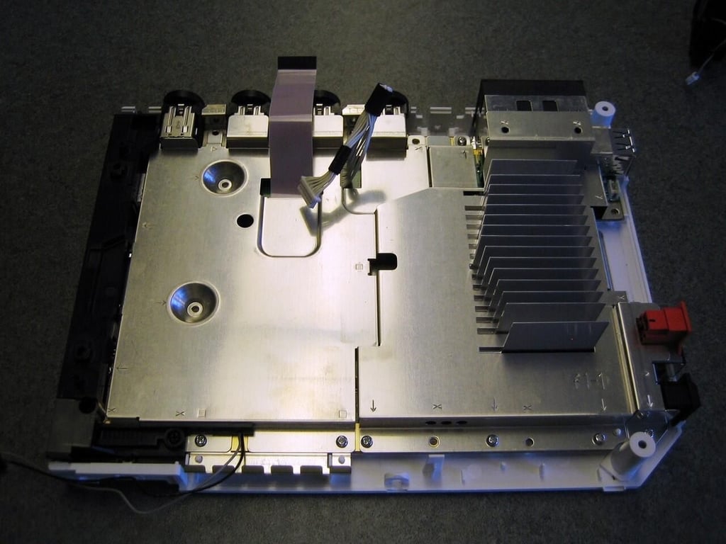
The the top cover removed, we get our first real look inside the Wii. A large metal shield still covers most of the Wii’s inner workings.
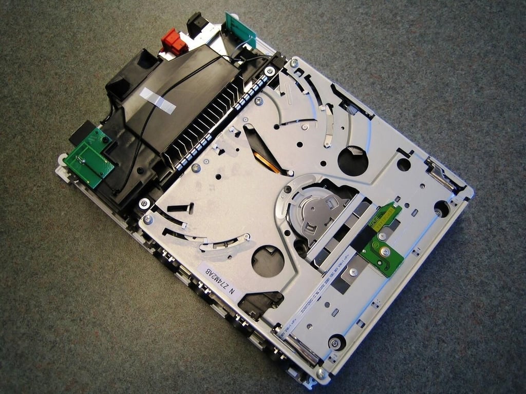
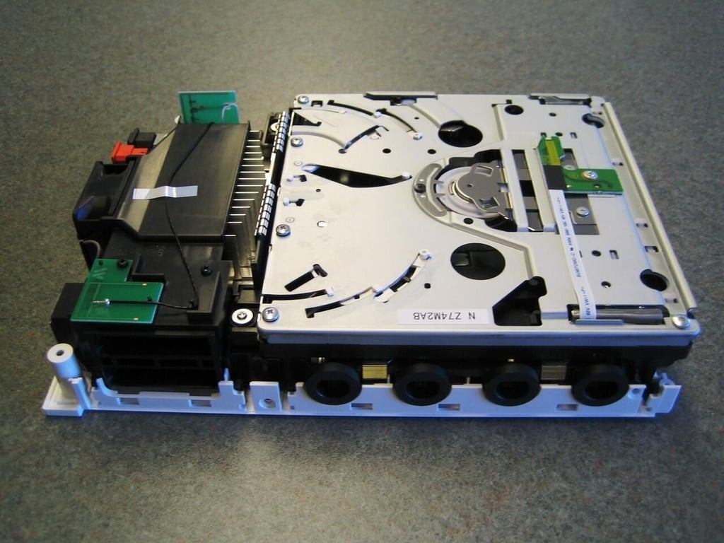
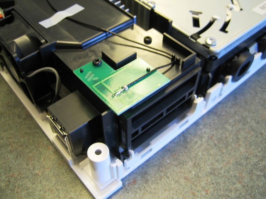
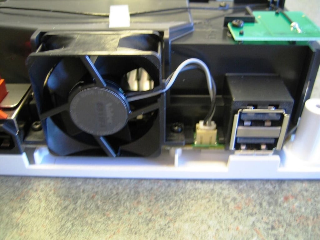
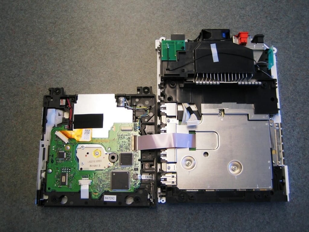
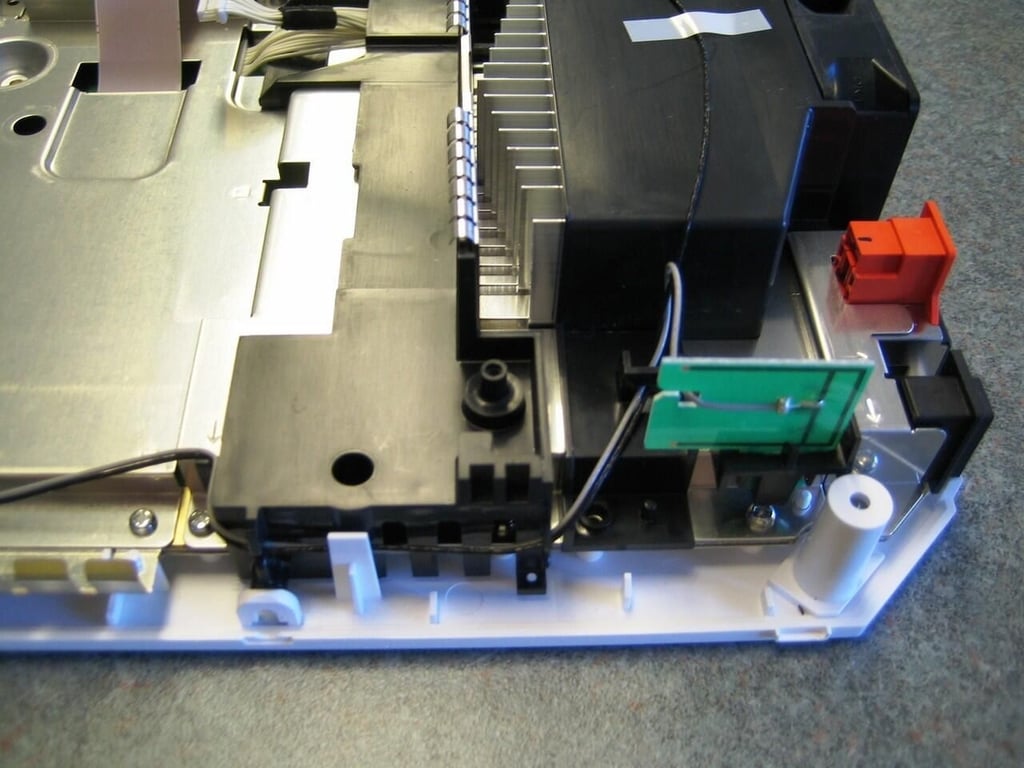
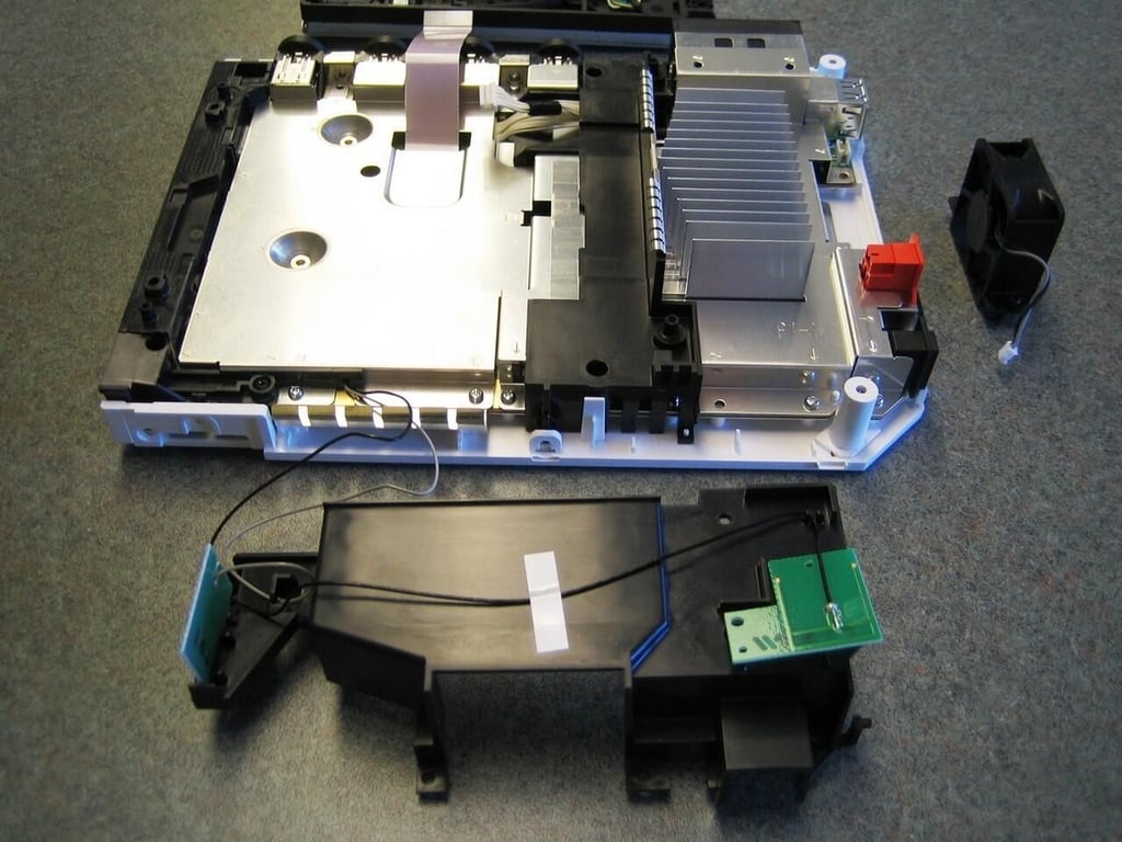
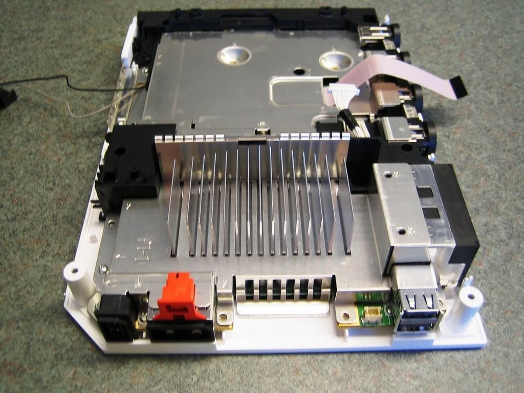
With the metal shield removed, we can see the wii’s optical drive, wireless two wireless antenna, cooling fan, and air intake cover.
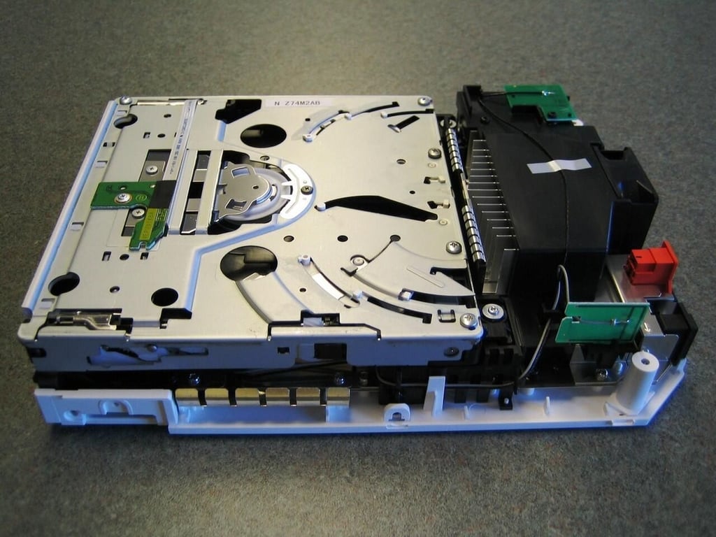
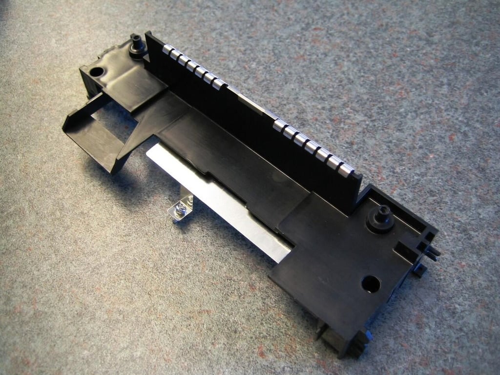
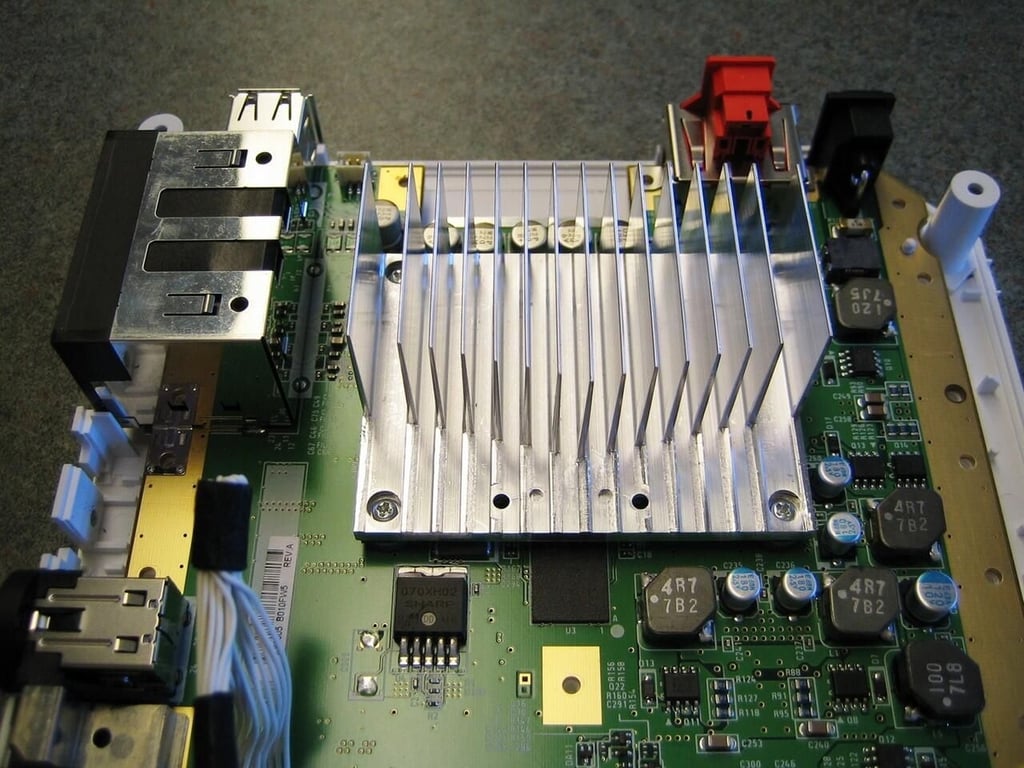
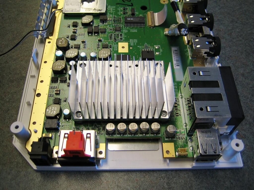
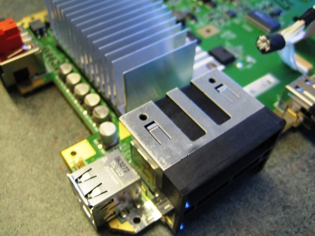
You can see the heatsink under the black intake cover.
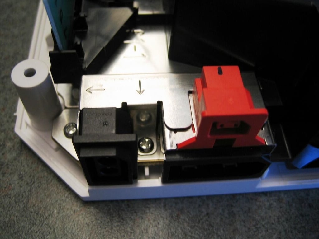
From the right side, you can see the GameCube memory card and controller ports.
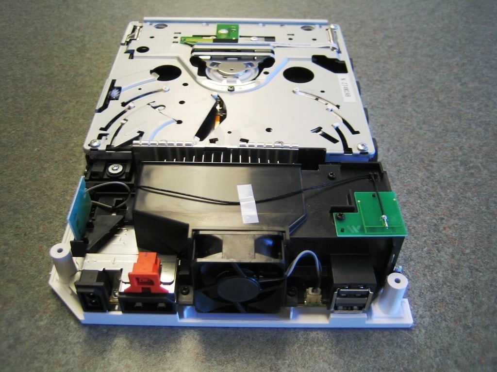
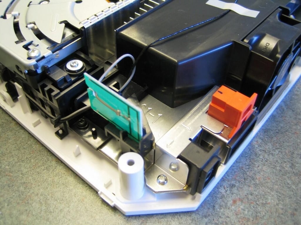
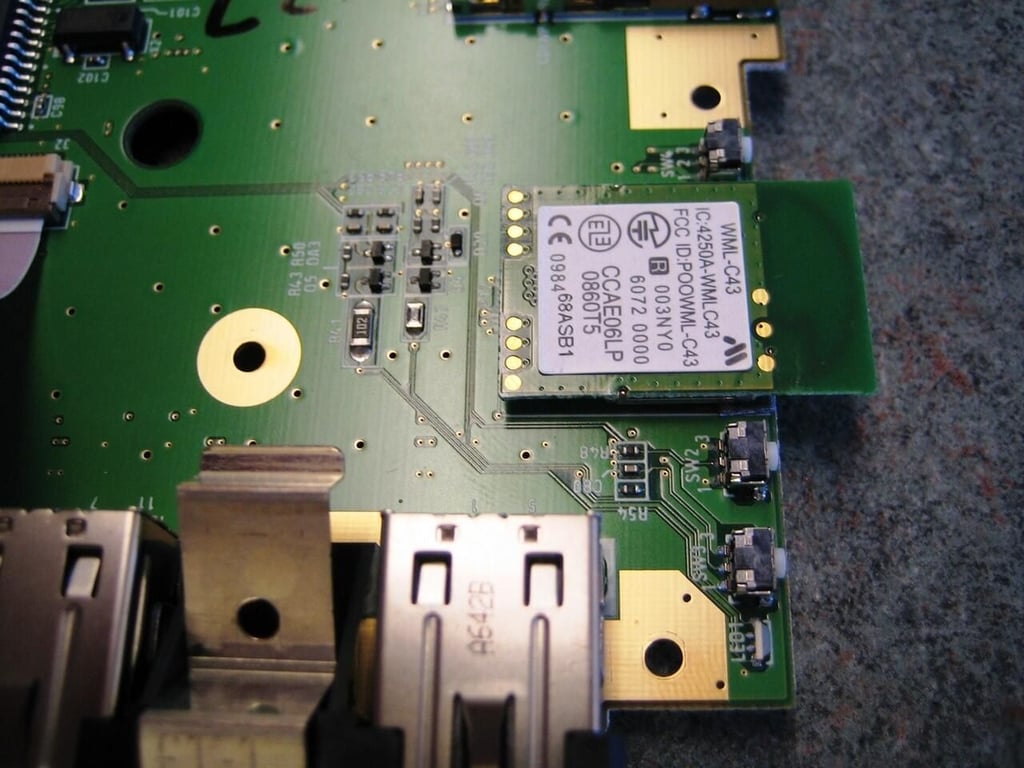
The Wii has two wireless antennas (green boards) mounted at the back of the machine.
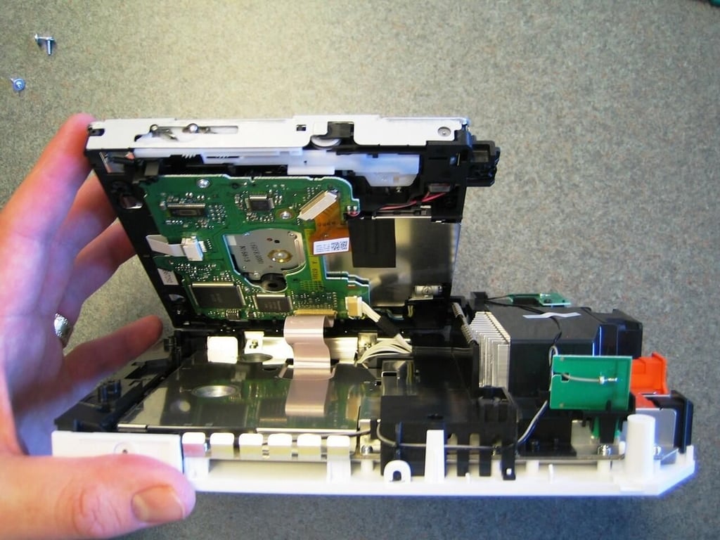
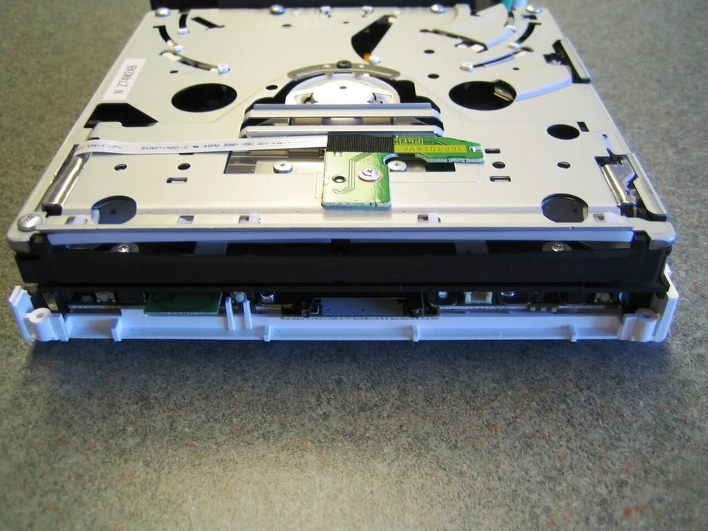
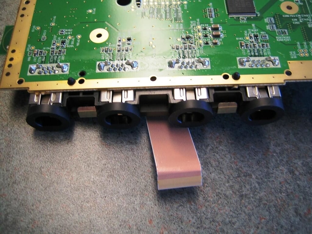
The optical drive is connected to the main PCB by a thin ribbon cable and larger power cable. By disconnecting the power cable you can set the drive flat.
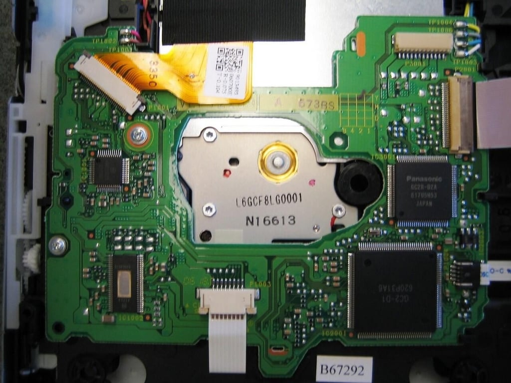
The optical drive PCB contains an Elpida chip offering 16MB of SDRAM–only viewable from the underside.
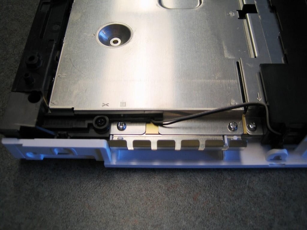
The two wireless antenna cords run under the motherboard protective metal shield. Take care not to break these small wires when removing the shield.
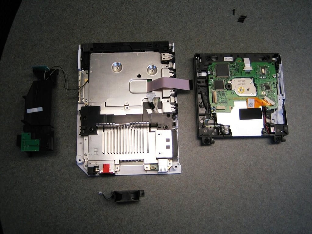
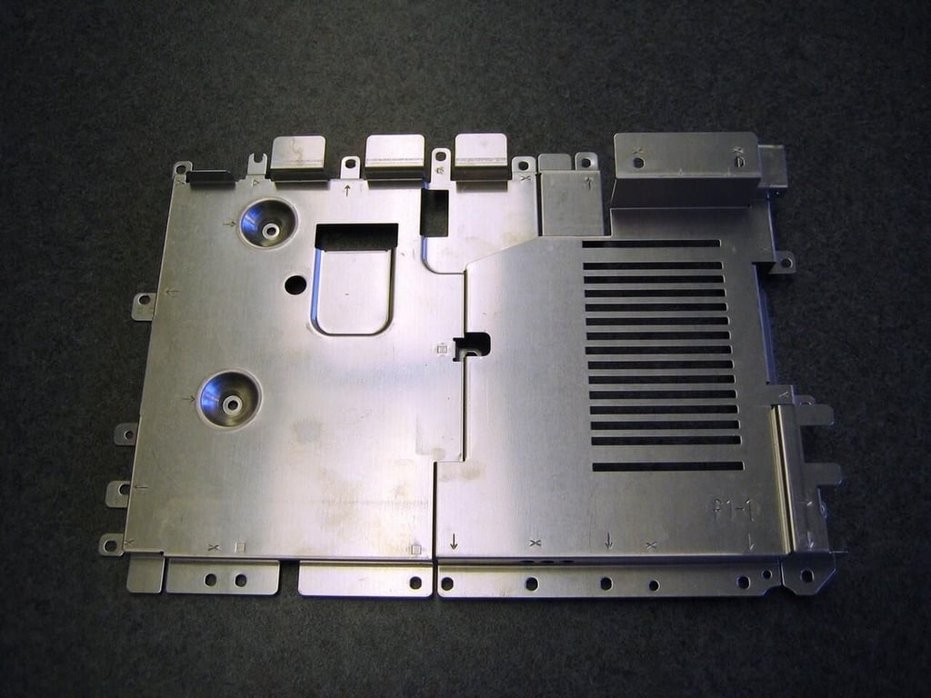
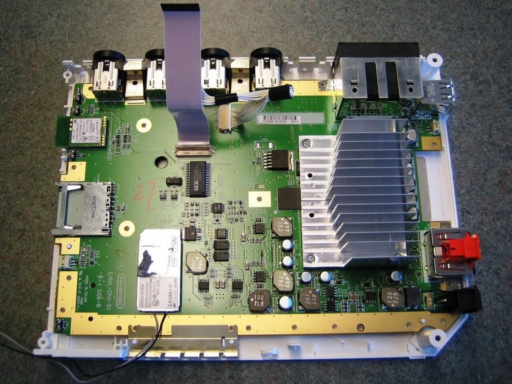
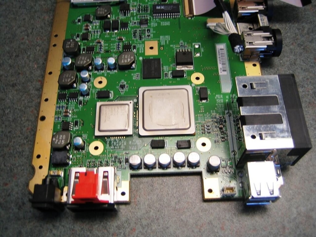
With the metal shield removed, we got our first look at the Nintendo Wii’s motherboard.
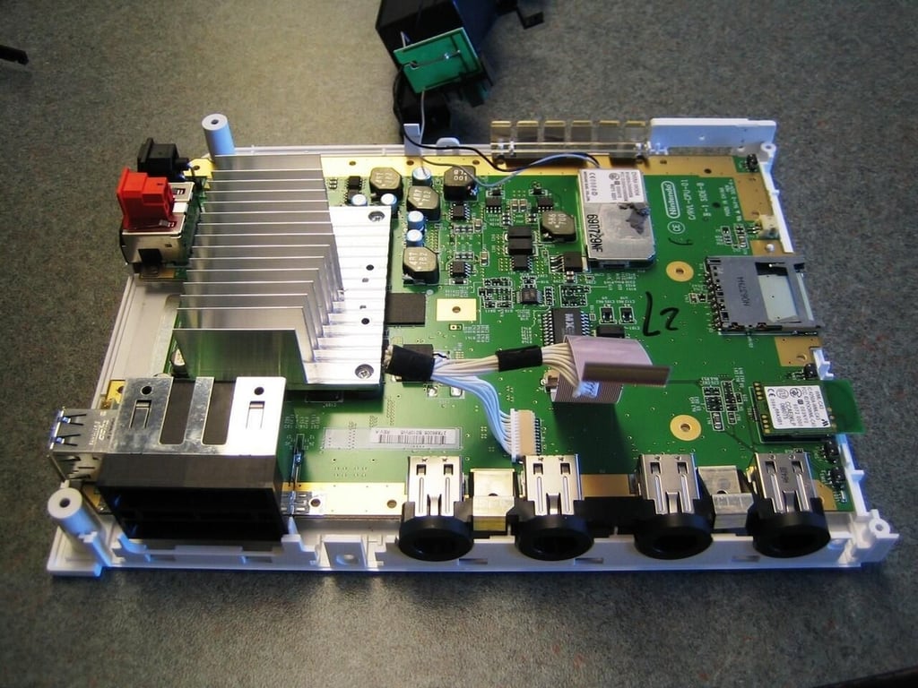
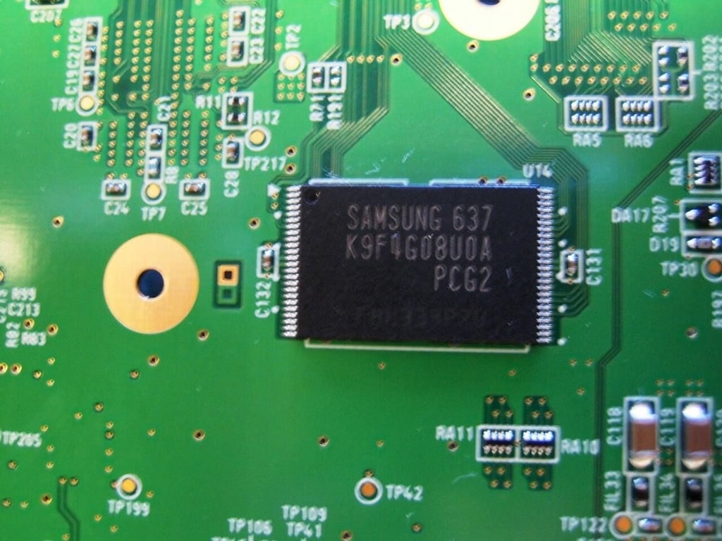
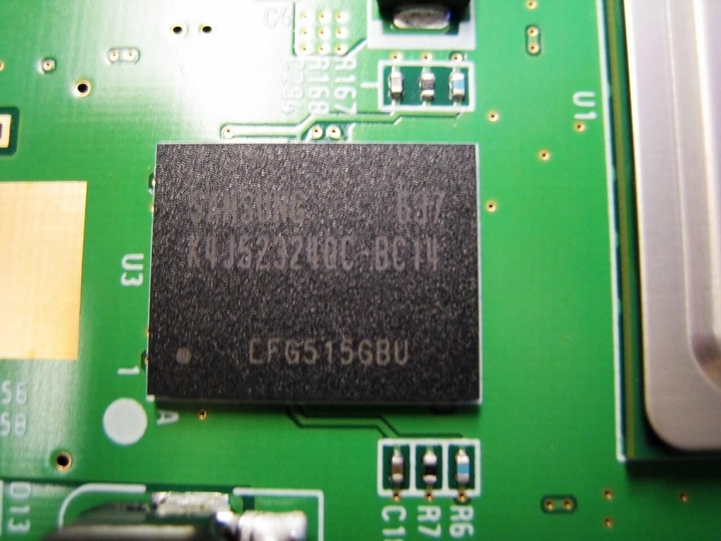
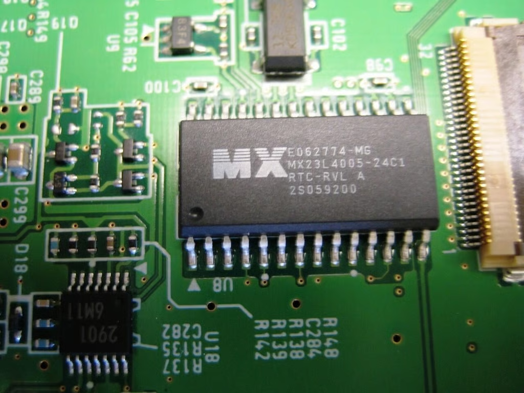
Samsung 512M x 8 Bit NAND flash memory
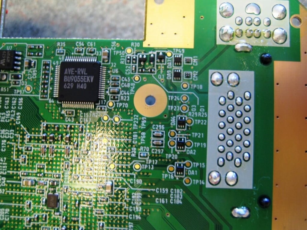
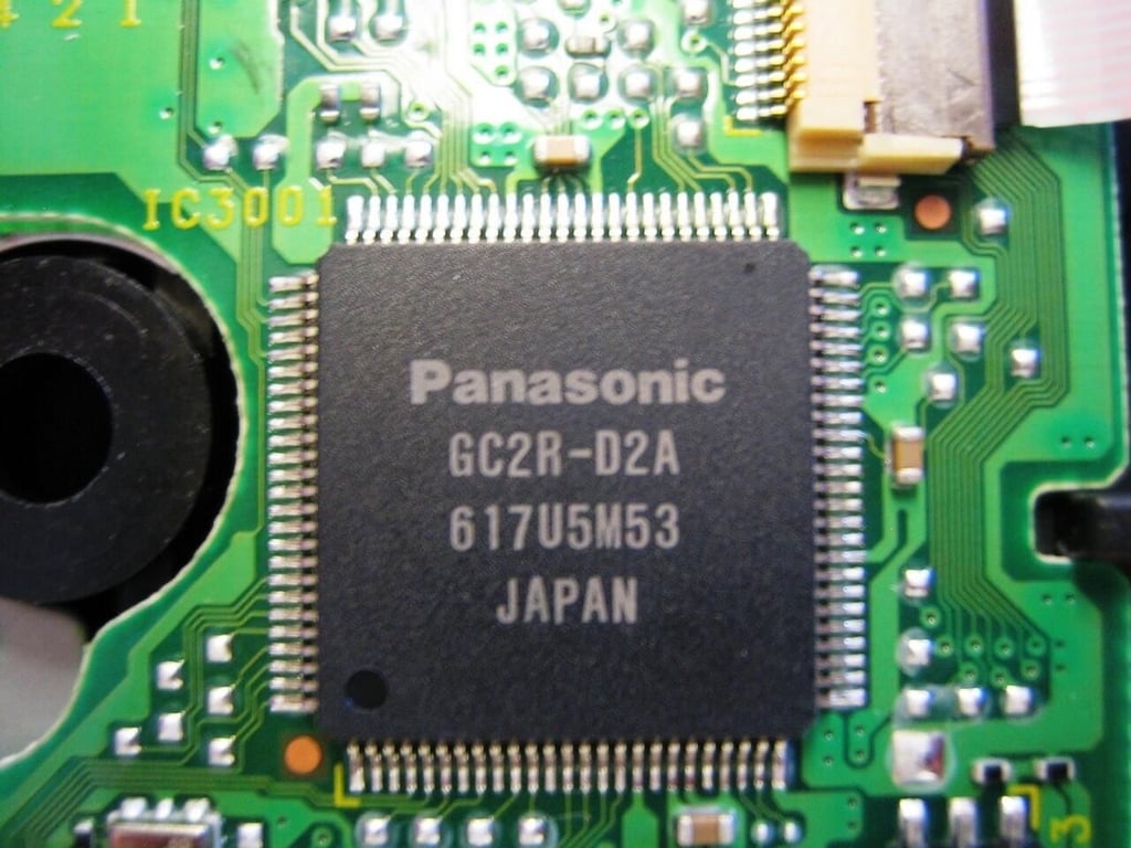
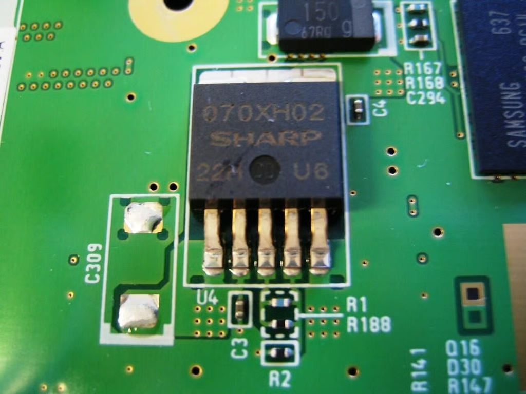
According to a forum post on wareu.org, this chip is the Wii’s audio/video encoder.
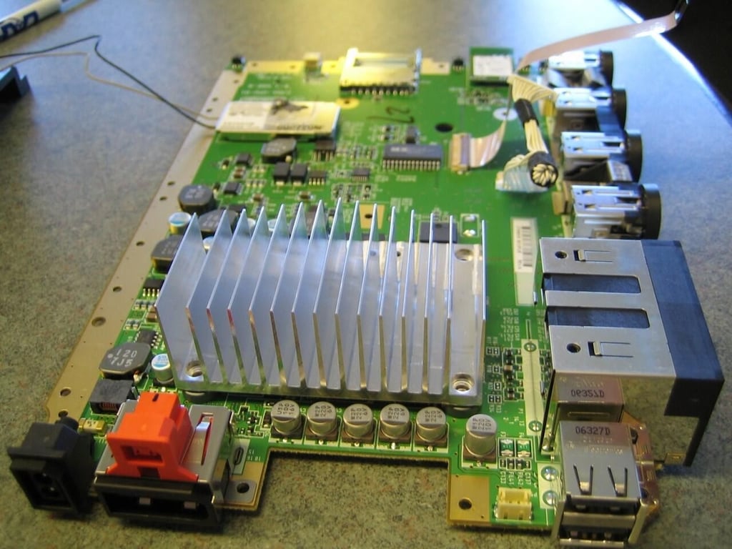
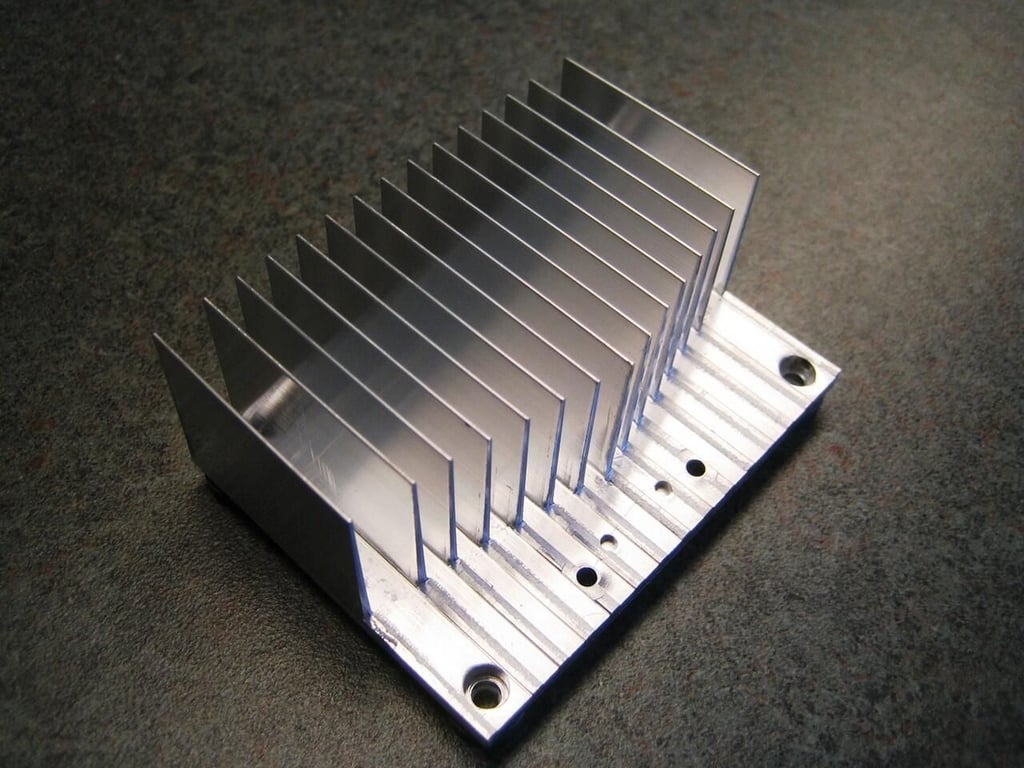
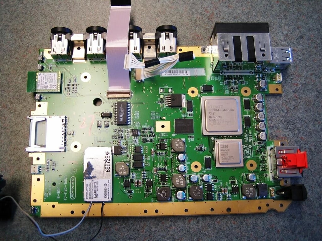
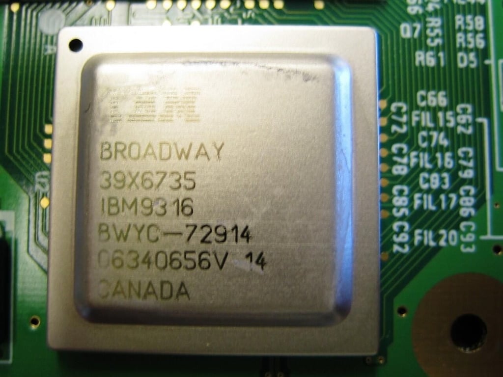
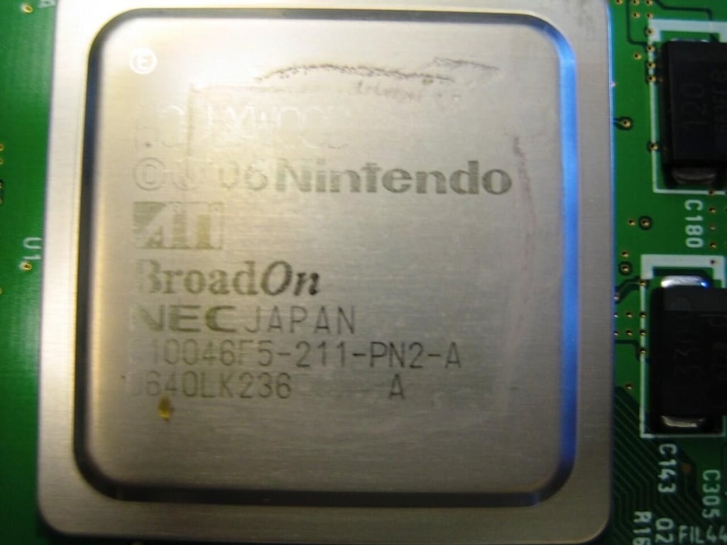
Removing the heatsink reveals the Wii’s CPU and GPU.

It took another hour or so, but I managed to completely reassemble the Wii. It even worked. There will Wii tennis for many weeks to come in the TechRepublic game room.
Bill Detwiler is the Editor for Technical Content and Ecosystem at Celonis. He is the former Editor in Chief of TechRepublic and previous host of TechRepublic's Dynamic Developer podcast and Cracking Open, CNET and TechRepublic's popular online show. Previously, Bill was an IT manager in the social research and energy industries. He has bachelor's and master's degrees from the University of Louisville, where he has also lectured on computer crime and crime prevention.


