QIC ( Quarter Inch Cartridge ) drives have been around since Moses was an intern, and justifiably so. They were relatively inexpensive, rock-solid devices ever since they were standardized in 1983. \n
\nThe capacities ranged from 60 Meg to 10 Gig, and the drives were often connected via floppy cable.\n\n
\n\nThis particular specimen was taken from a server that I removed from service about 8 years ago. It was the last in a long line of servers that all had QIC drives in them. We used them in our remote offices ( our backups were usually less than 100M ), and had little or no trouble with them, mechanically. Taking this particular machine out of service was one of the first tasks that I was assigned when I started with this company. The office was moving and we decided to upgrade the server which was, as I recall, a 133Mhz Intel with about 64Mb RAM, and a 350Mb HDD. The OS used a Linux kernel to boot, but ran a custom OS called PickPro. I remember that the server was tucked under the admins desk, and when I lifted it up to remove it, roaches ran out – uuuugh.\n
\nDoes anyone have any stories of IT workplace condition “h-e-double hockey sticks” (as the kids say)?\n
\nAfter that little digression…Our goal here it to see what makes our intrepid unit here tick. \n
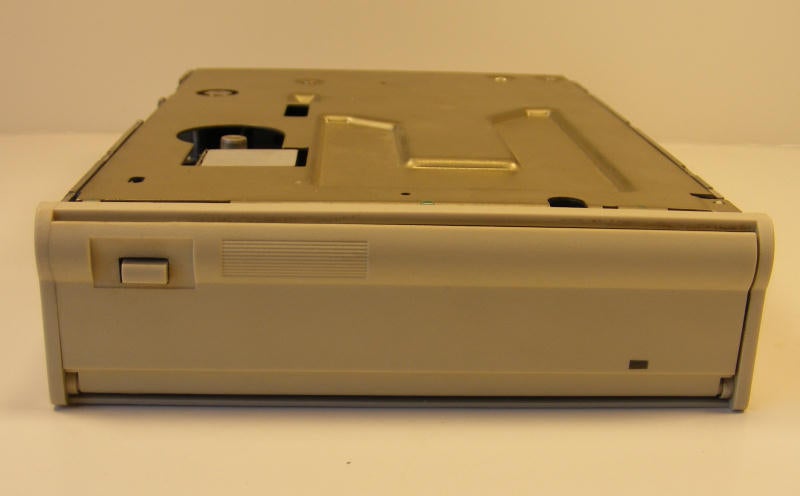
\nHere we have the first of many frames featuring our Sankyo CP-1508. The sturdy eject button, and a singular status led.
All images by Drew McBee for \u00a9 TechRepublic
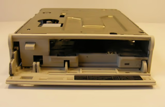
The entry gate open, we see the huge slot waiting for its mate.
All images by Drew McBee for \u00a9 TechRepublic
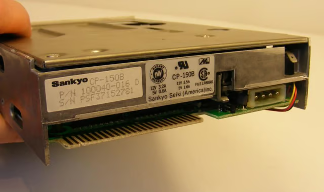
Here’s the back – the business end if you will, gives us our specs and so forth. \n\nNote the ground tab on the right and the flat connector for the ribbon.
All images by Drew McBee for \u00a9 TechRepublic
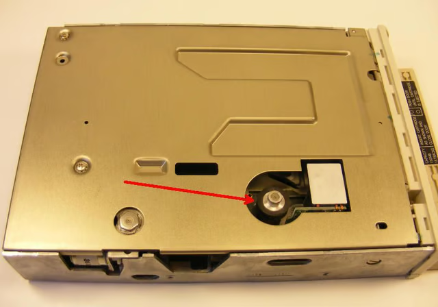
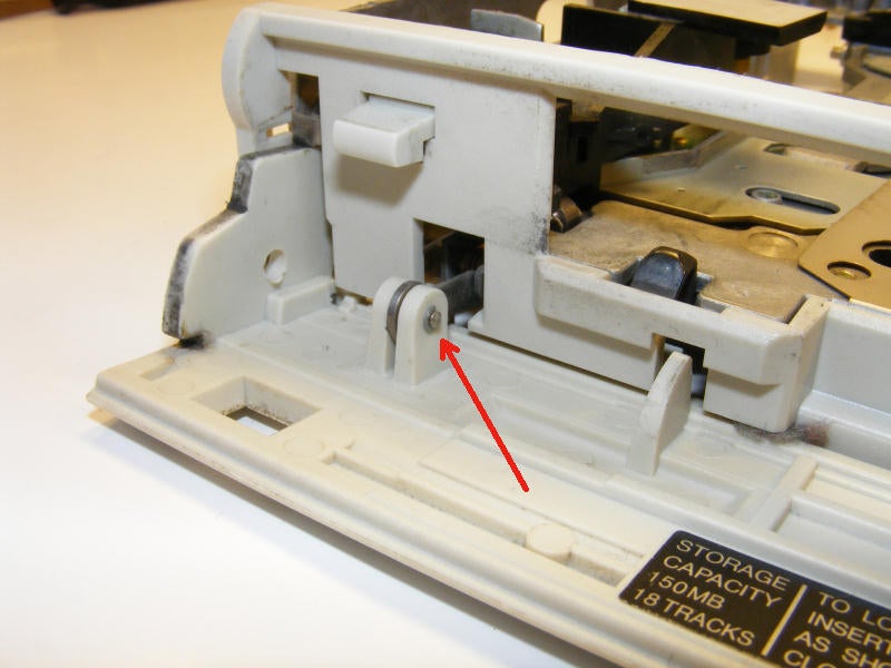
The top of the unit. The red arrow points to the rubber drive wheel which we’ll see more of soon.
All images by Drew McBee for \u00a9 TechRepublic
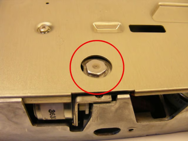
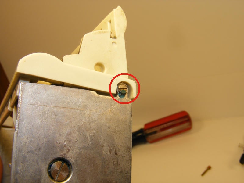
This is interesting – the head adjustment nut. Again – we’ll see more about how this works later.
All images by Drew McBee for \u00a9 TechRepublic
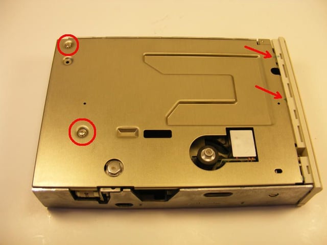
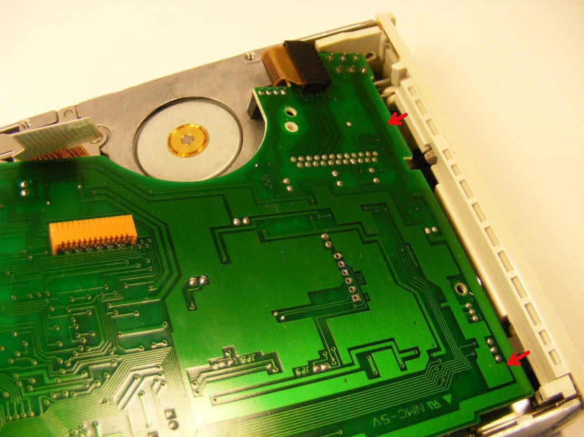
Only a couple of screws (red circles) holding the lid down. Some hard-to-see (click the image to enlarge) adhesive drops pointed out by red arrows. We see those often on this drive and those like it.
All images by Drew McBee for \u00a9 TechRepublic
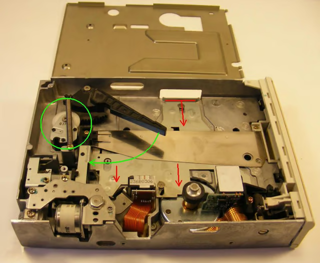
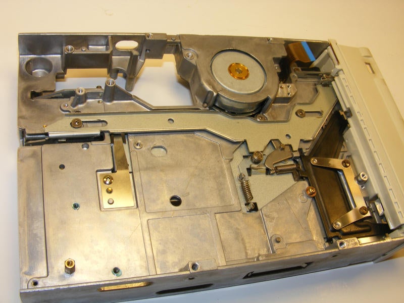
Here we have the major organs in full view. We’ll look at the individual groups shortly.\n
\nI am going to try to show what happens when a tape is loaded and what components move into place and where. \n
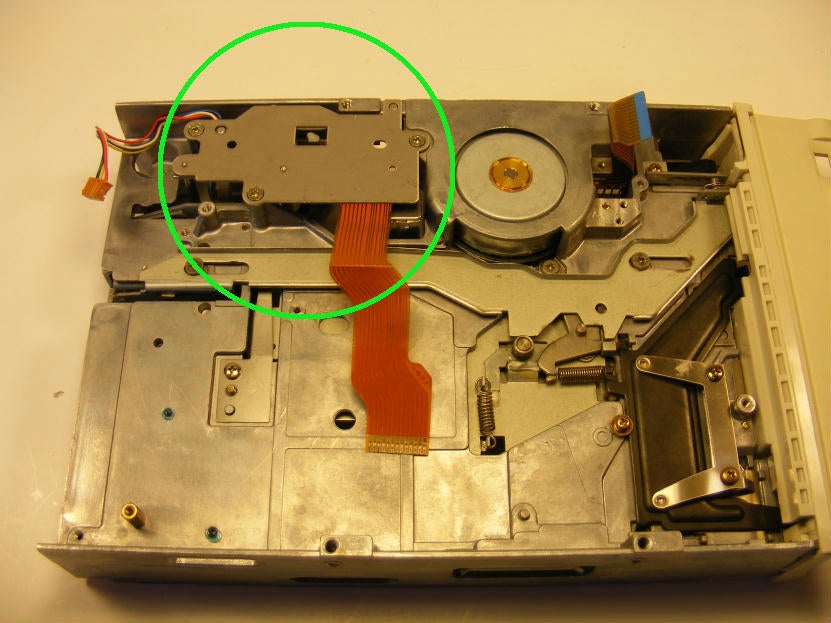
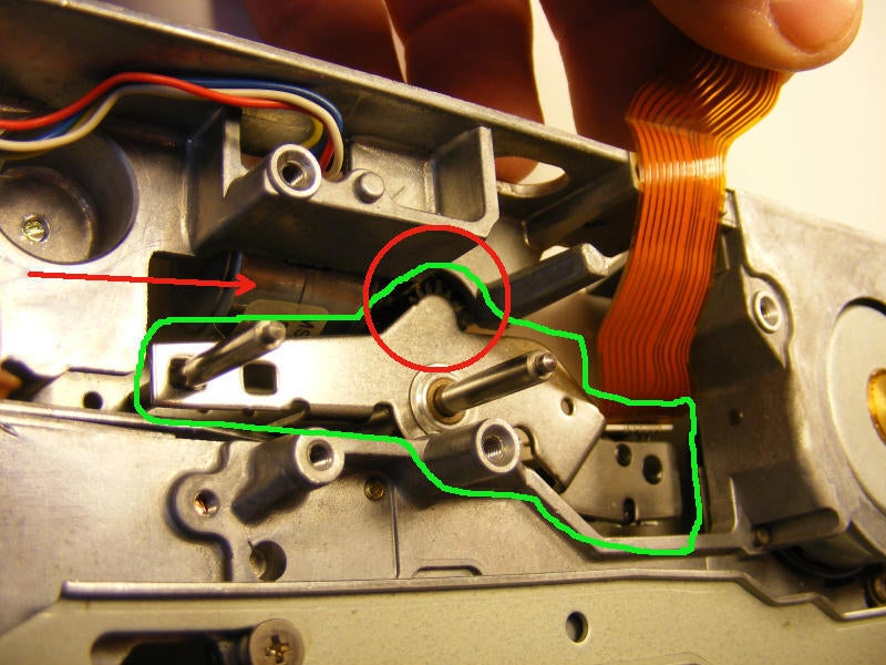
\n\nIn the green, we see the eject mechanism and loading damper in one. The circle shows the little gear-reduction unit that slows the loading and ejecting.\n
\n\nThe red arrows show the tray that, when the tape is fully inserted, moves the QIC into place.
All images by Drew McBee for \u00a9 TechRepublic
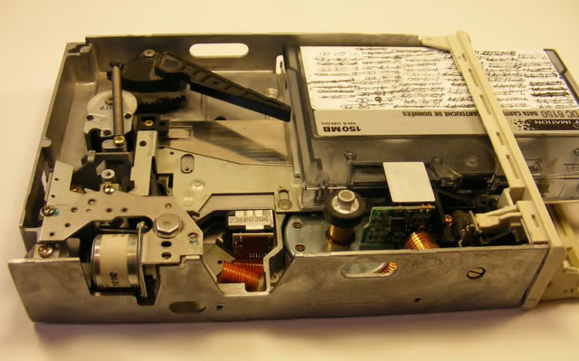
The QIC in the first stage of insertion – just touching the eject bar.
All images by Drew McBee for \u00a9 TechRepublic
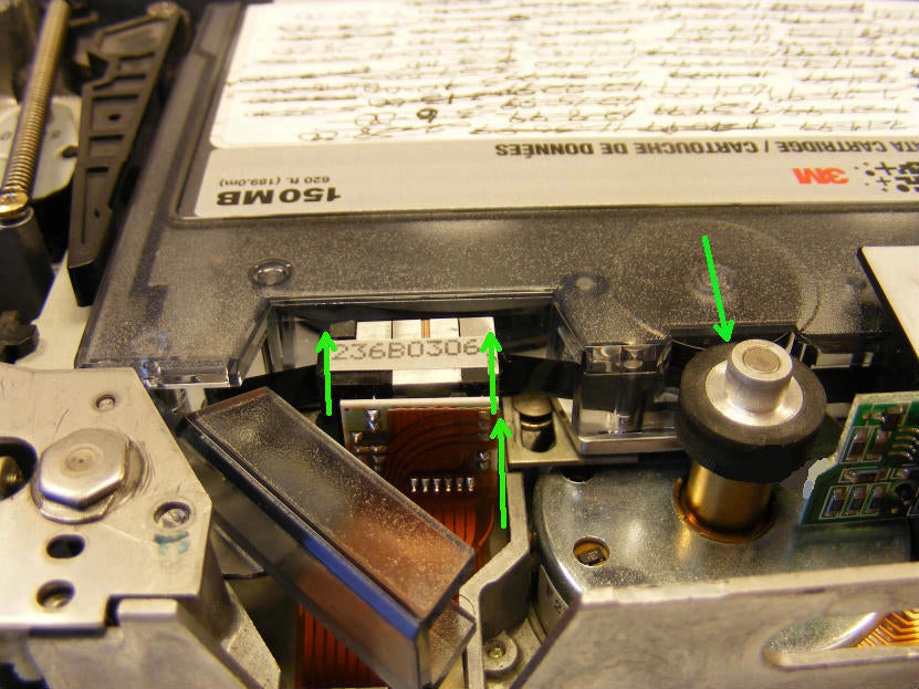
When the door is closed behind the tape, the slide plate shown earlier draws the QIC into the RW heads and the drive wheel (green arrows).\n
br />\nThe drive wheel, as we will see later, is fixed in its position, save for a couple of pivot pins and a small spring.
All images by Drew McBee for \u00a9 TechRepublic
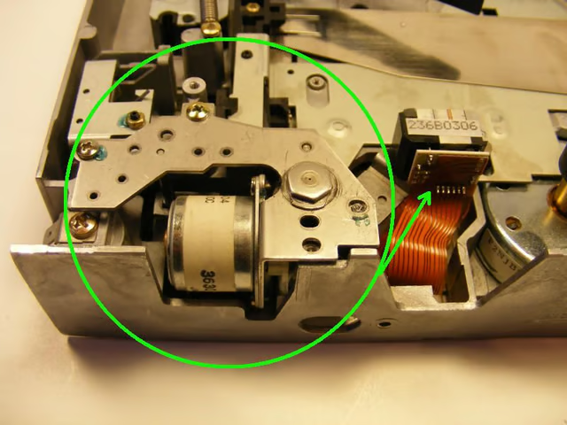
This shows our head alignment motor assembly. We’ll see lots of detail on this later.
All images by Drew McBee for \u00a9 TechRepublic
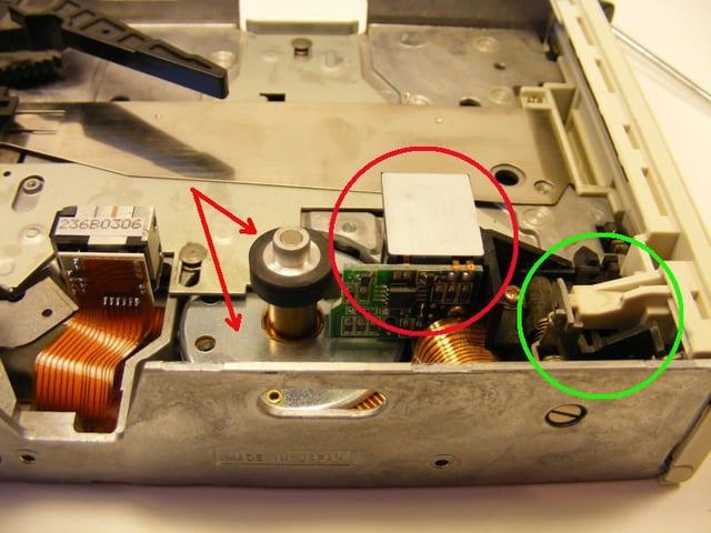
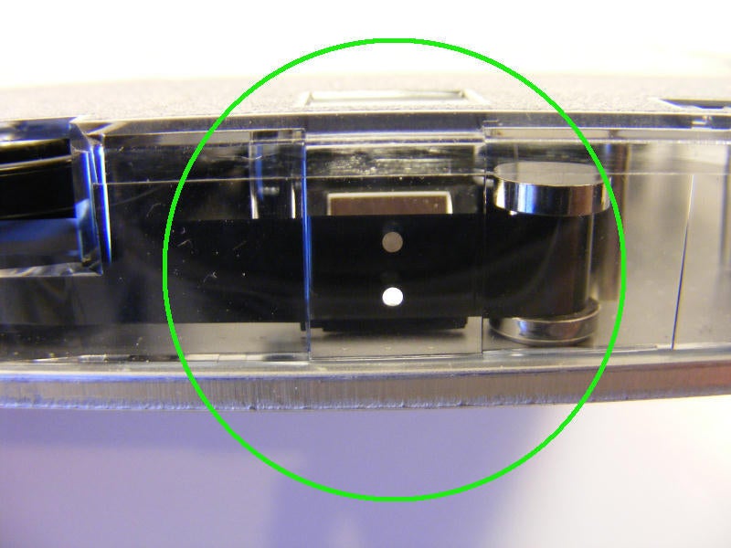
Here the red arrows point to our drive wheel and the associated motor. \n
\nThe red circle shows the end of tape sensor, and the green circle shows (albeit badly) the write protect mechanism.\n
We’ll have all of this apart, so you get a better look further along.\n
All images by Drew McBee for \u00a9 TechRepublic
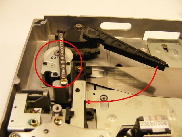
Here is another look at our eject mechanism, showing the range of motion of the lever and the manly spring that propels the QIC from its slot when so instructed.
All images by Drew McBee for \u00a9 TechRepublic
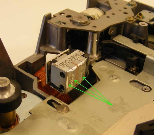
Here is a look at the R/W head for our device. The green arrows show that this one has seen many, many backups in its time.
All images by Drew McBee for \u00a9 TechRepublic
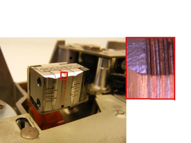
I “borrowed” my daughters Eye-Clops (highly recommended by me, by the way) and took a picture of what I believe is the erase magnet part of the head. \n
\nThe Eye-Clops requires quite a bit of light (works best in sunlight), which I did not have much of in the the winter February months that I took the pictures in, but overall, I think it is a pretty cool extreme close up. Notice the tooling marks. You’ll get a much better view by clicking the image to enlarge.
All images by Drew McBee for \u00a9 TechRepublic
…is that eject mechanism. Three screws and a hefty spring.
All images by Drew McBee for \u00a9 TechRepublic
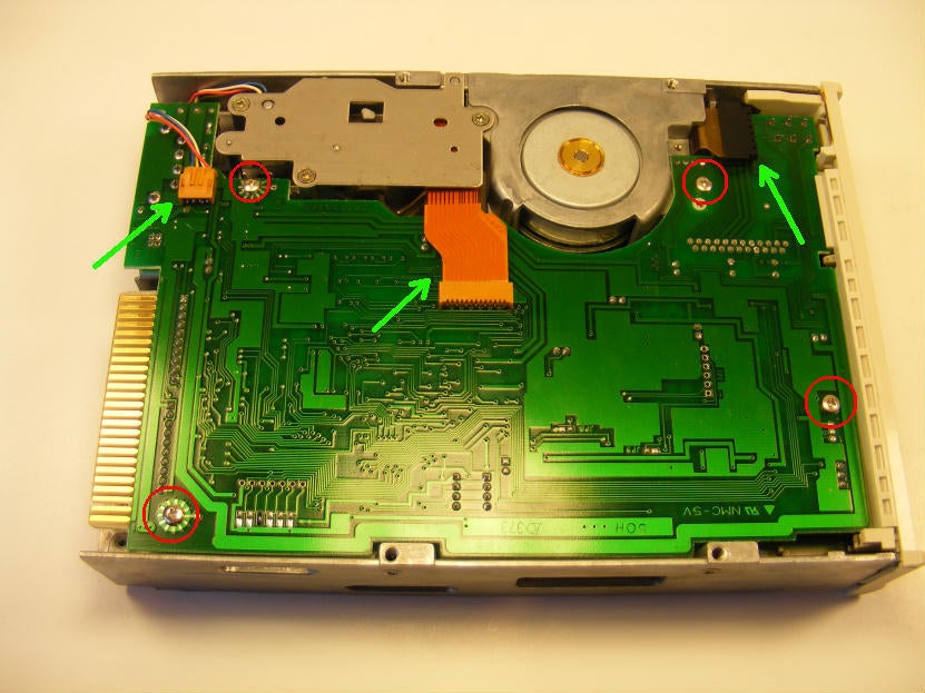
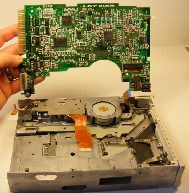
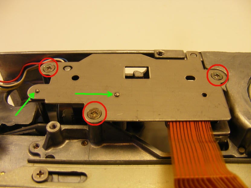
Next is the mainboard held in by a few screws shown in red circles. The ribbon and power connectors shown in green.
All images by Drew McBee for \u00a9 TechRepublic
The board must tilted up and out. Only while tilted, can that last ribbon be removed.
All images by Drew McBee for \u00a9 TechRepublic
The controller and drive apart now…
All images by Drew McBee for \u00a9 TechRepublic
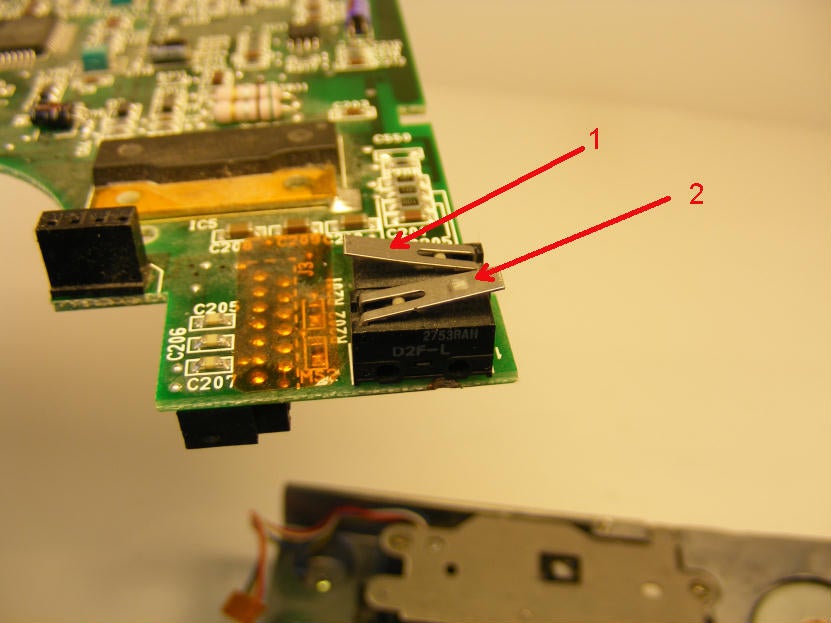
Two micro switches on the board: 1-write protect switch, 2-Door closed switch.
All images by Drew McBee for \u00a9 TechRepublic
We begin cracking the head alignment mechanism by removing the cover plate shown in green.
All images by Drew McBee for \u00a9 TechRepublic
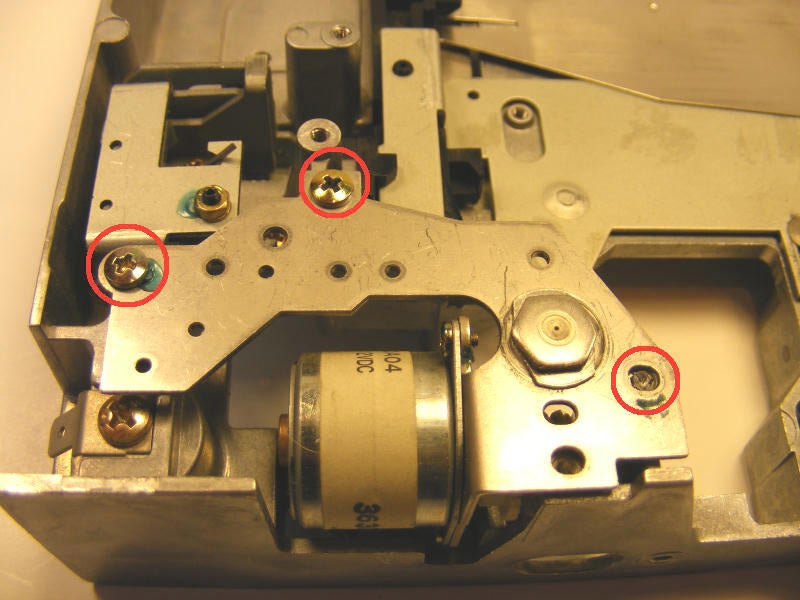
Three screws shown in red and two, soon to be seen, guide pins shown in green.
All images by Drew McBee for \u00a9 TechRepublic
I tried not to clutter this up, but there was a number of things I wanted to point out here.\n
\nFirst, the green outline shows the bracket that the RW head mounts to – you can see the ribbon that goes to it.\n
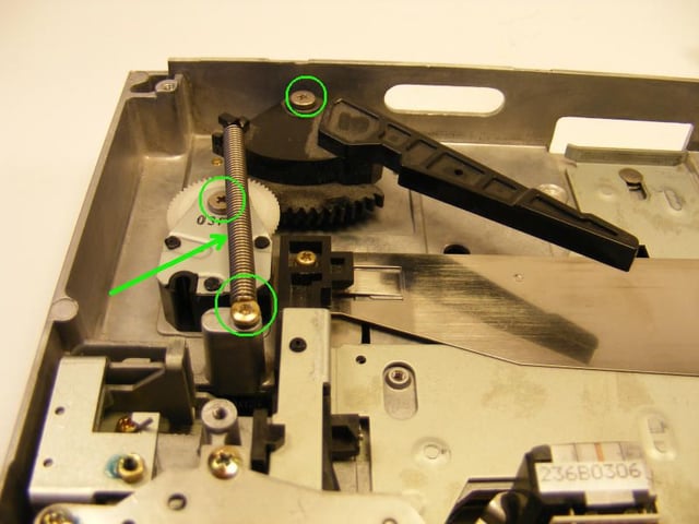
\nNext, the red circle shows the gear that floats up and down, and carries the bracket with it, to align the head to the tape. The red arrow points to the motor and said drive gear.
All images by Drew McBee for \u00a9 TechRepublic
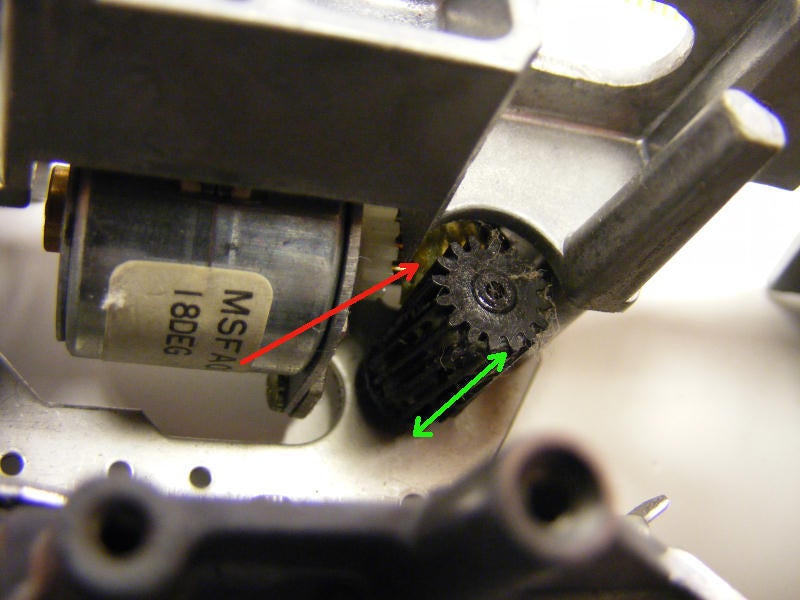
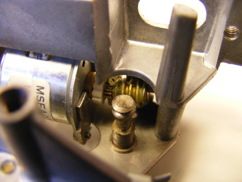
Now that the bracket and pins have been removed, we get a better look at how this works. The motor turns a worm gear (red arrow – barely visible yet) at varying speed against the black one. The black gear (we will see) has threads inside that force it up or down (green arrow) when driven by the worm gear. This allow VERY fine control of our RW head. This also allows manual adjustment of the head during maintenance, via the hex bolt shown in the 6th frame.
All images by Drew McBee for \u00a9 TechRepublic
Here we see the internal threads that operate our adjuster gear (black). \n
\nAlso, as a side note, the red arrow points to a lever which moves the heads into position when the QIC is inserted.\n\n
All images by Drew McBee for \u00a9 TechRepublic
Another look at the adjustment mechanism without the plastic gear this time.
All images by Drew McBee for \u00a9 TechRepublic
Just about everything that we are going to remove is gone now. \n
\nNext we’ll move topside, as they say in the Navy.
All images by Drew McBee for \u00a9 TechRepublic
Now we need to get the top bracket for the alignment mechanism removed. Three screws holding it in – I broke one off as you can see here – believe it or not. They were pretty tight.
All images by Drew McBee for \u00a9 TechRepublic
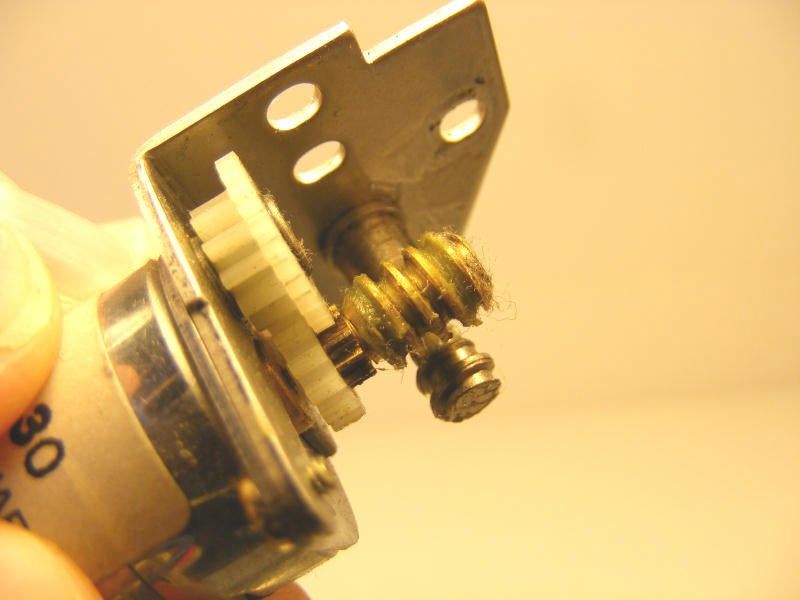
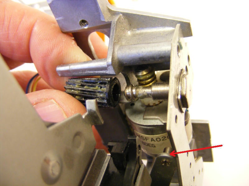
A look at the worm gear and drive motor completely removed. \n
\nThat will be just about all from the alignment mechanism.
All images by Drew McBee for \u00a9 TechRepublic
Next we need to get the face plate and door off. \n
\nInitially, I thought that micro-sized clip (red arrow) needed to come off, but found that the arm just hooked over the pin that was held by the clip.
All images by Drew McBee for \u00a9 TechRepublic
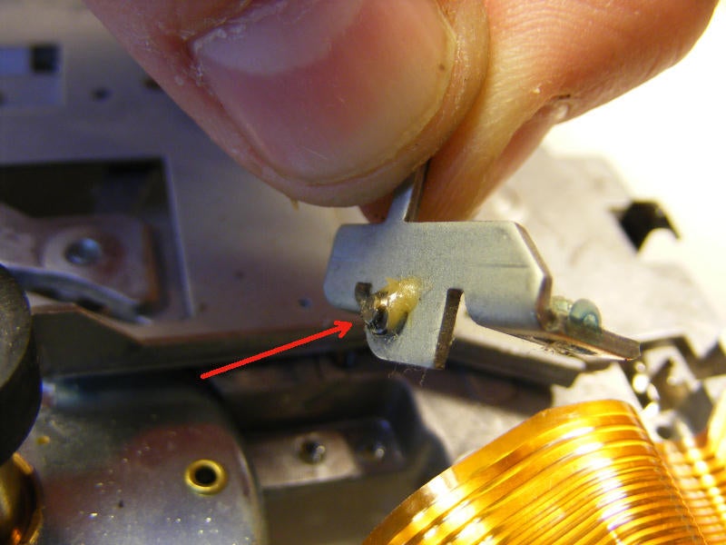
Next were a couple of screws, one on each side, that were secured by the green adhesive that we have seen several times already.
All images by Drew McBee for \u00a9 TechRepublic
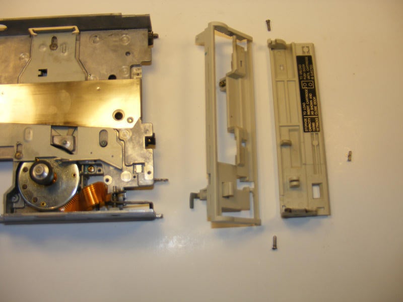
Once the screws were out, the parts of the faceplate and door just unsnapped and laid out.
All images by Drew McBee for \u00a9 TechRepublic
Next we take off the end of tape sensor. One screw in red holds it in place, along with an alignment pin.
All images by Drew McBee for \u00a9 TechRepublic
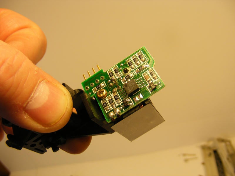
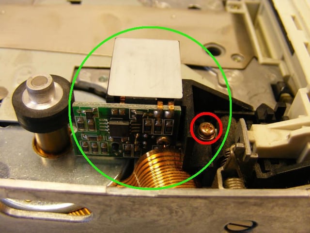
Here an image of the small circuit board that controls the photo eyes.
All images by Drew McBee for \u00a9 TechRepublic
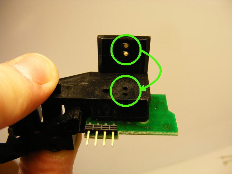
A good look at the photo eyes and receivers here in green. This whole mechanism was pretty interesting – a mirror is mounted at an angle in the QIC and reflects the ‘light’ towards the receiver. During normal operation, the circuit should remain open – but when the two small holes in the tape come along (in a later frame) the circuit closes and tells the drive that it is at the end of the tape, to which it can react accordingly.
All images by Drew McBee for \u00a9 TechRepublic
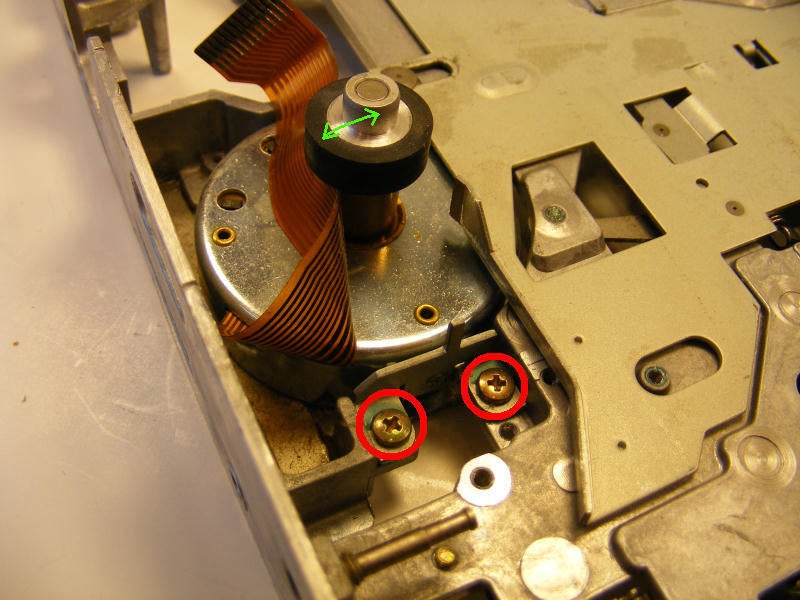
Now we remove the bracket that holds our drive motor in via the two screws in red.\n
\nIt is also a good time to show the range of motion of the drive wheel – shown by the small green arrow. It leans “in” by default, and when the GIC is fully loaded, it pushes against the wheel ensuring adequate friction.
All images by Drew McBee for \u00a9 TechRepublic
A surprisingly small shoulder that supports the drive motor. Its size is put into context by the relative girth of my unsightly thumb and forefinger.
All images by Drew McBee for \u00a9 TechRepublic
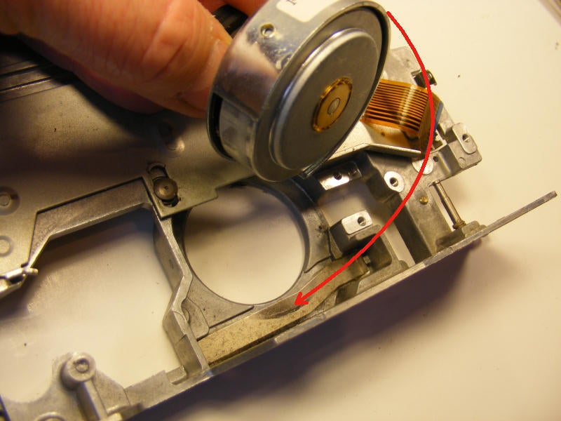
Bracket removed, the motor comes out easily. It was supported on the other side by an equally small stub.\n
\nNotice, courtesy of our friend the arrow, the spring that kept tension on our tapes all those years.
All images by Drew McBee for \u00a9 TechRepublic
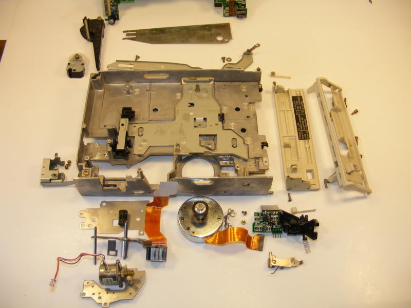
So there she is – again, Cracked open for your viewing pleasure. I did not remove some of the brackets and rails, because: 1 – it would be boring for the readers, and 2 – some were riveted in anyway.\n
\nI continued this gallery by adding a small section (next) about the QIC itself, as it really is an interesting and durable piece of legacy equipment. Enjoy.
All images by Drew McBee for \u00a9 TechRepublic
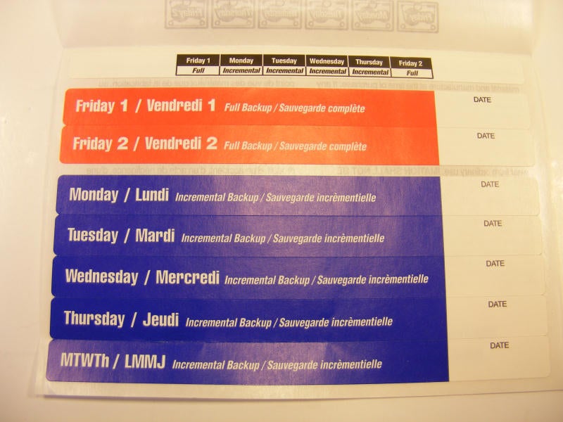
I found it interesting that they assumed at the time that everyone would use the same rotation scheme. Notice (by enlarging the pic) the guidance chart at the top in black.
All images by Drew McBee for \u00a9 TechRepublic
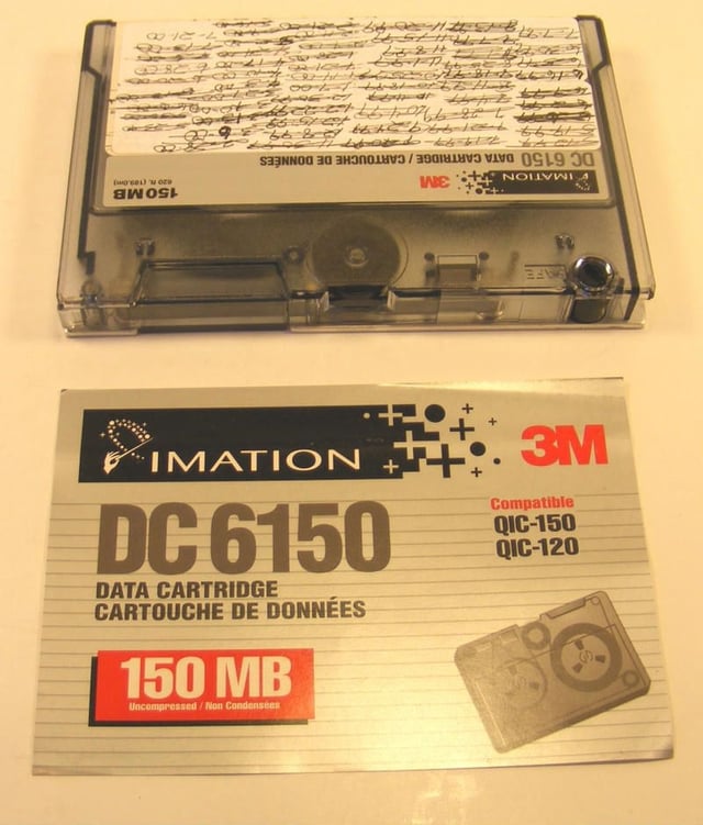
A DC 6150 cartridge will be our victim here.\n
\nNotice the tape, and all of the dates on it. We ran that one a little over a year. The Last date written there, by me, almost 9 years ago.
All images by Drew McBee for \u00a9 TechRepublic
We can see the two holes marking the end of the tape, as discussed in a previous frame. We can see the mirror behind it, the small window of top of the tape, and get an understanding of how the photo eyes on the drive work.
All images by Drew McBee for \u00a9 TechRepublic
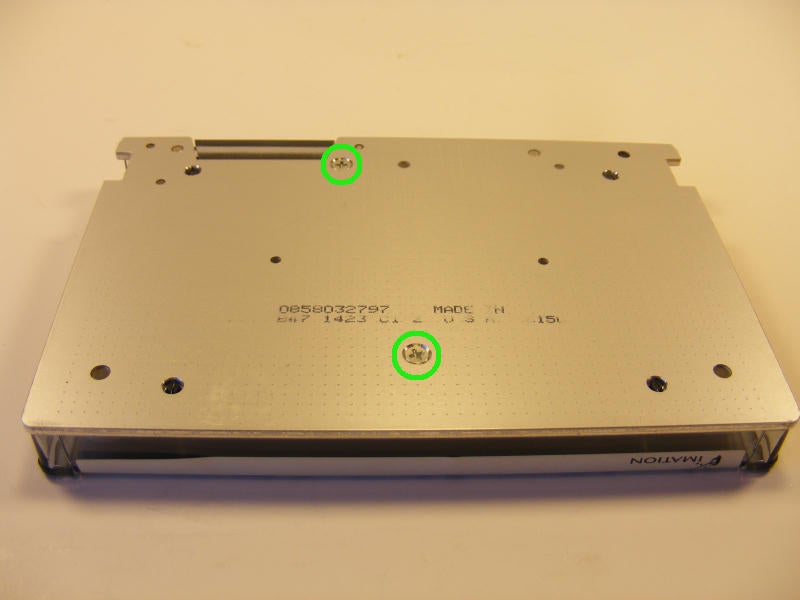
To get the tape apart, there are only two screws – in green as shown.
All images by Drew McBee for \u00a9 TechRepublic
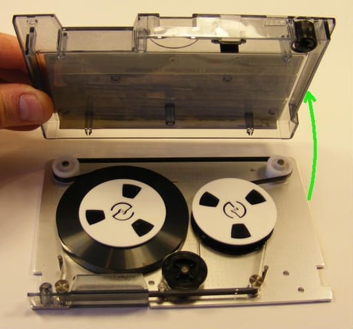
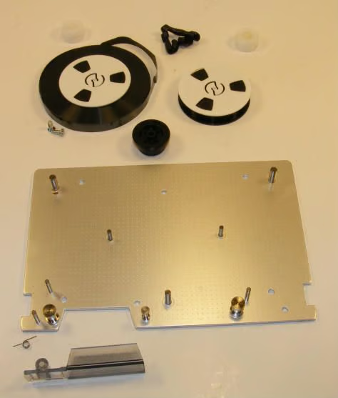
The cover easily lifts off now, exposing our reels.
All images by Drew McBee for \u00a9 TechRepublic
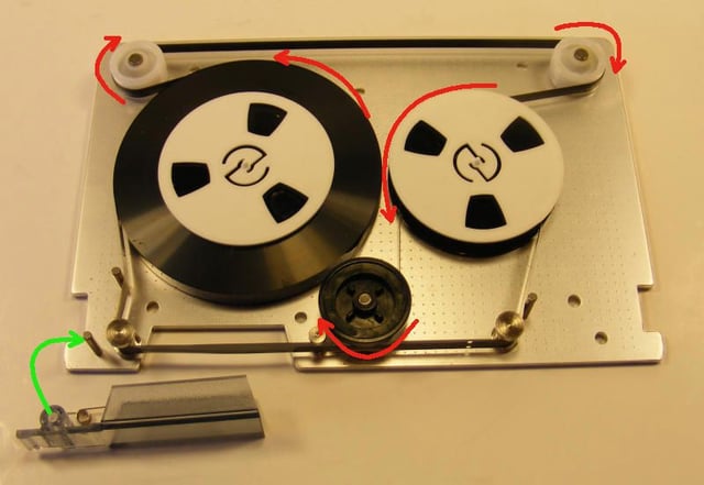
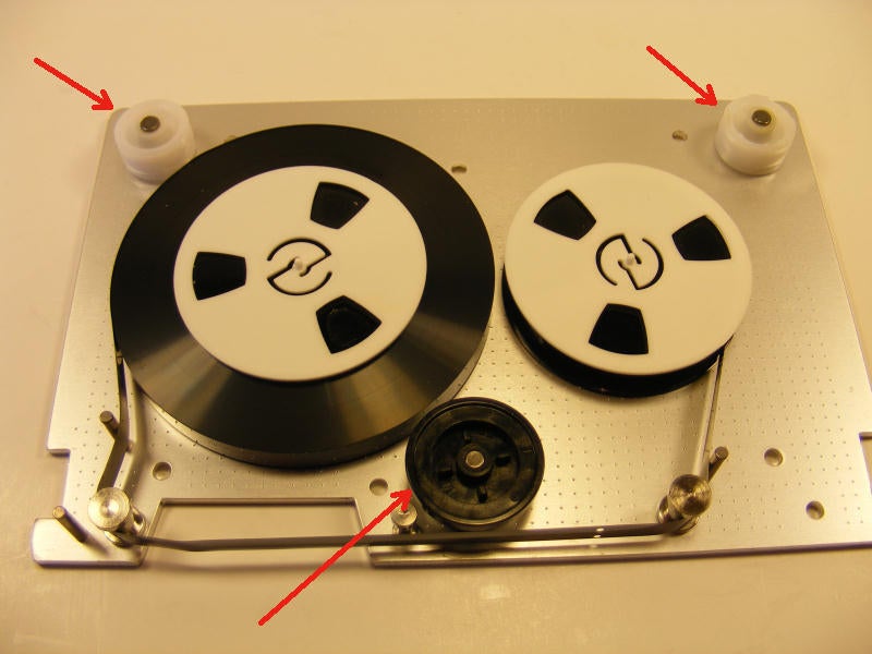
The access door just lifts off of a small pin along with it’s spring(green arrow).\n
\nThe red arrows show how the drive belt threads around its wheels and reels. The drive motor on the tape drive drives the black wheel, which turns the tape reels. \n
\nWe’ll start by removing the drive belt.
All images by Drew McBee for \u00a9 TechRepublic
Next is to remove the three drive rollers.
All images by Drew McBee for \u00a9 TechRepublic
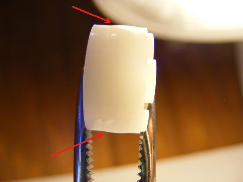
The wheels in this and the next frame show the ONLY thing that kept the drive belt in place. No, no grooves or guides as I would expect, but barely perceptible raised ridges. That fascinated me really.
All images by Drew McBee for \u00a9 TechRepublic
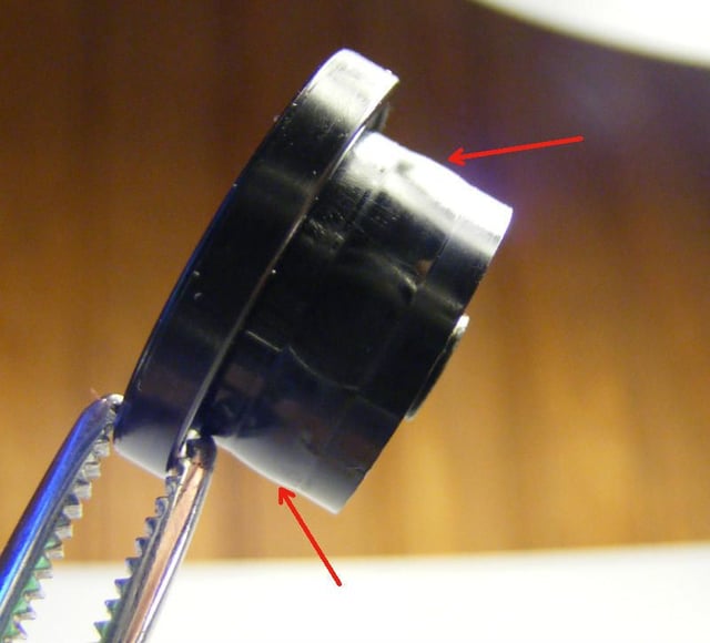
The same thing here – same ridges. I had to wonder what that does to the belt over time, and I think we see in the next frame.
All images by Drew McBee for \u00a9 TechRepublic
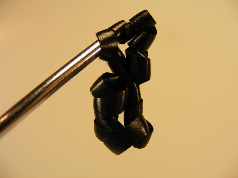
When the belt came off, it immediately coiled up into itself. A result, I think, of the ridges in the rollers.
All images by Drew McBee for \u00a9 TechRepublic
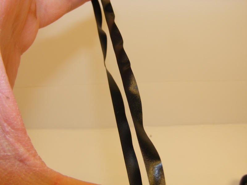
This belt was made from a really curious material – it had a bit of a texture, and was flexible, but not like a rubberband as you would expect. It was a lot like the material that is used to insulate power cords – a flexible plastic if you will.
All images by Drew McBee for \u00a9 TechRepublic
Another piece of valuable hardware blown up for your viewing pleasure.\n
\nTo those that wonder, yes, it did all go back together and was in working order. But since I did not have ribbon or a suitable adapter, I could not verify a backup.
All images by Drew McBee for \u00a9 TechRepublic


