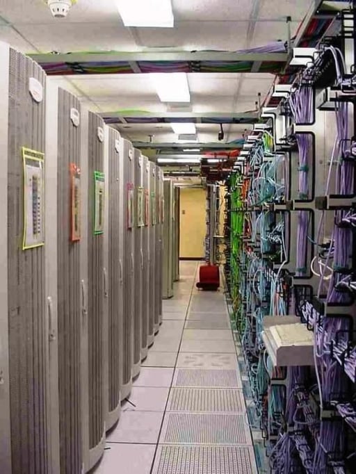
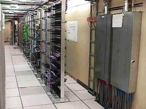
Redesigned Data Center (1 of 7)
Finished view of a 2,000-square-foot data center upgrade and expansion project
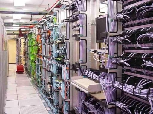
Redesigned Data Center (2 of 7)
Finished view of a 2,000-square-foot data center upgrade and expansion project
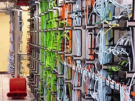
Redesigned Data Center (3 of 7)
Finished view of a 2,000-square-foot data center upgrade and expansion project
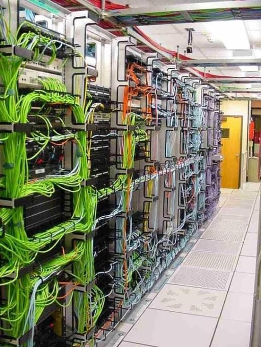
Redesigned Data Center (4 of 7)
Finished view of a 2,000-square-foot data center upgrade and expansion project
Redesigned Data Center (5 of 7)
Finished view of a 2,000-square-foot data center upgrade and expansion project
Redesigned Data Center (6 of 7)
Finished view of a 2,000-square-foot data center upgrade and expansion project
Redesigned Data Center (7 of 7)
Finished view of a 2,000-square-foot data center upgrade and expansion project
Old server cabinet layout (1 of 6)
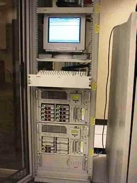
A 42U cabinet typically supported a maximum of 8 servers. Each server normally required one network connection, a KVM cable, and one or two power cables.
Old server cabinet layout (2 of 6)
As servers continue to shrink, the required connectivity per server doubled.
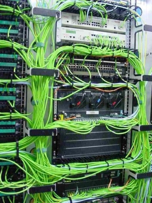
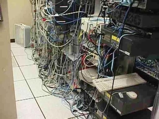
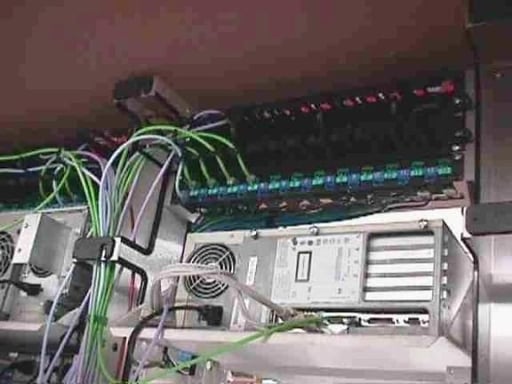
Old server cabinet layout (3 of 6)
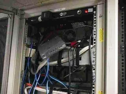
A harrowing example of measures resorted to by a network administrator in order to increase the number of network connections in a cabinet (notice the 8-port hub hanging by its cables).
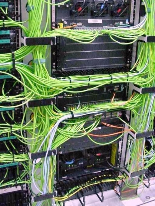
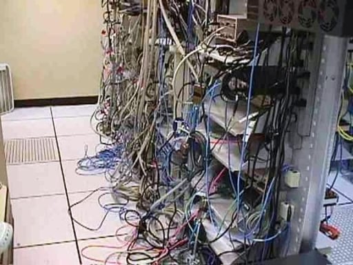
Old server cabinet layout (4 of 6)
Physical layer administration is neglected in many data centers across the country, especially those without a Network Facilities Designer on staff.
Old server cabinet layout (5 of 6)
Cabling is often mistakenly regarded as trivial and unimportant to overall network operations.
Old server cabinet layout (6 of 6)
Plexiglas inserts in front doors were once characteristic to most cabinet designs. Unfortunately, for most cabinet manufacturers, this configuration became common practice. However, increasing heat dissipation needs of modern servers has resulted in cabinet owners having to replace their cabinets, or purchase replacement panel inserts with 80% perforation.
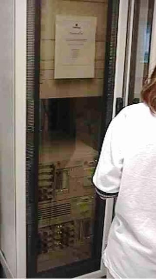
New server cabinet layout (1 of 6)
Modern cabinets can contain as many as 288 blade servers, and up to 42 small-form-factor servers. Such deployments require special attention to power distribution, network connectivity, and heat dissipation needs of the server cabinet.
New server cabinet layout (2 of 6)
Modern server cabinets must be configured to support a minimum of 24 servers, each with: – dual power connections – dual LAN connections – dual SAN connections – a KVM connection plus an additional connection for RS-232, T-1, modem, or network connection for remote monitoring/management.
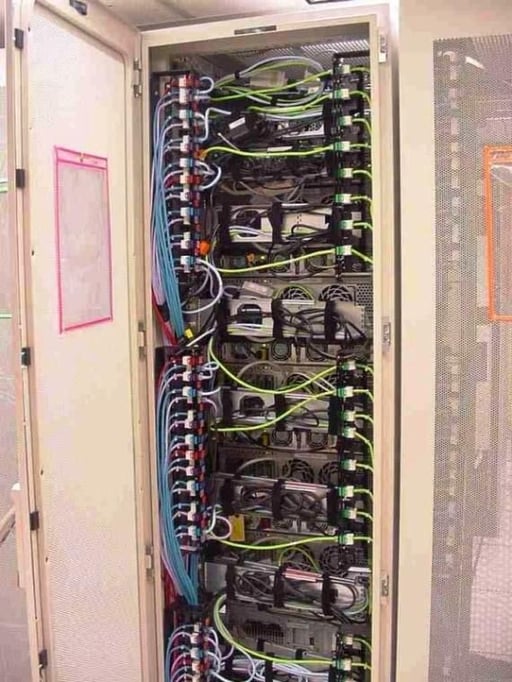
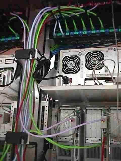
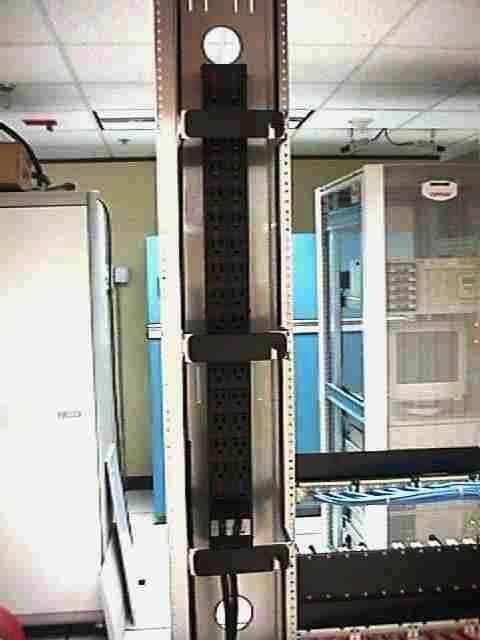
New server cabinet layout (3 of 6)
Using an extension at the rear of the cabinet enables vertical mount of up to 6 patch panels, which provides extra space for high-density distribution of network cabling. This revolutionary design offers increased connectivity per cabinet, with maximum flexibility, while retaining all attributes of a structured cabling infrastructure.
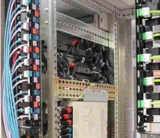
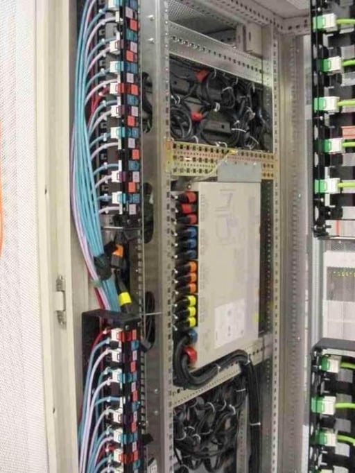
New server cabinet layout (4 of 6)
Pictured here is a 42U server cabinet consisting of 96 UTP connections, with provisions for up to 48 fiber connections. 96 copper UTP connections are subdivided into 4 color-coded networks: – 2 for redundant LAN connections, – a KVM connection, – and one additional segment for RS-232, T-1, and modem line connectivity. Additional provisions are available for up to 48 fiber connections, subdivided into 2 segments for redundant SAN or NAS connectivity.
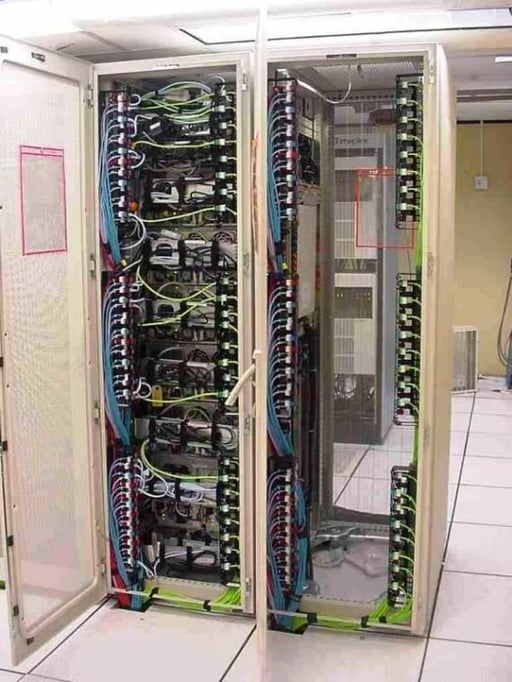
New server cabinet layout (5 of 6)
Three of these vertically mounted patch panels will net 72 connections per side. Upon closer look, you will notice three alternating colors of RJ-45 connectors distributed across the left side of this 42U server cabinet. Each color represents a separate physical network.
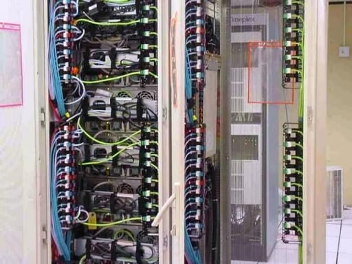
New server cabinet layout (6 of 6)
Dual Power Distribution Units in the cabinet’s sidewalls offer up to 48 power connections per cabinet. This provides 100% fail over redundancy. And by mounting them in a “Zero Rack U” configuration, full cabinet utilization for equipment is permitted with no wasted space for power strips.
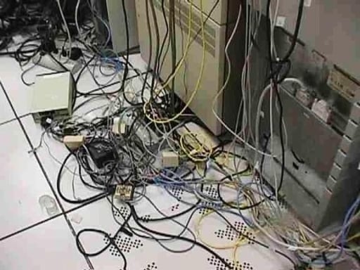
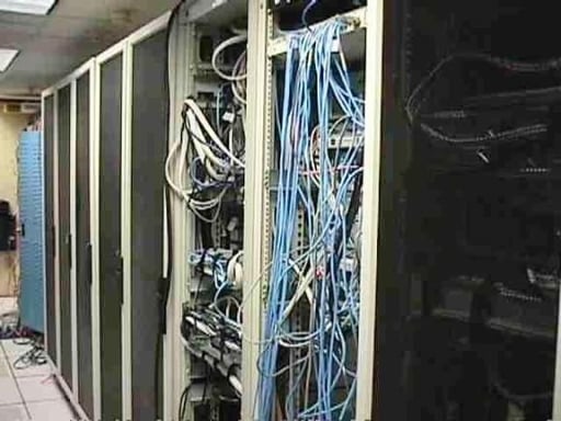
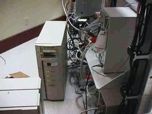
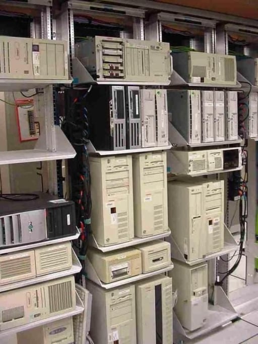
Old tower server deployment (1 of 4)
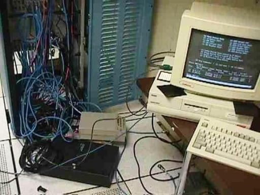
This is an example of what can happen when physical layer administration is left up to network administrators, and not assigned to a specific person or group.
Old tower server deployment (2 of 4)
This is an example of what can happen when physical layer administration is left up to network administrators, and not assigned to a specific person or group.
Old tower server deployment (3 of 4)
This is an example of what can happen when physical layer administration is left up to network administrators, and not assigned to a specific person or group.
Old tower server deployment (4 of 4)
This is an example of what can happen when physical layer administration is left up to network administrators, and not assigned to a specific person or group.
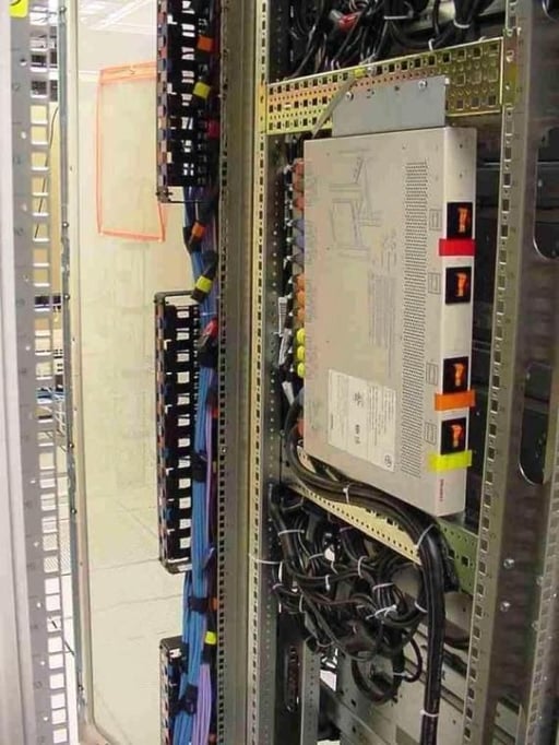
New tower server deployment (1 of 5)
Vertical mount, dual input power strips offer a maximum number of connections, 100% failover redundancy, and occupy zero rack units.
New tower server deployment (2 of 5)
Vertical power strip occupies zero rack units, has dual 120V, 20A inputs, each circuit feeds 16 receptacles, resulting in 32 receptacles with 100% redundancy.
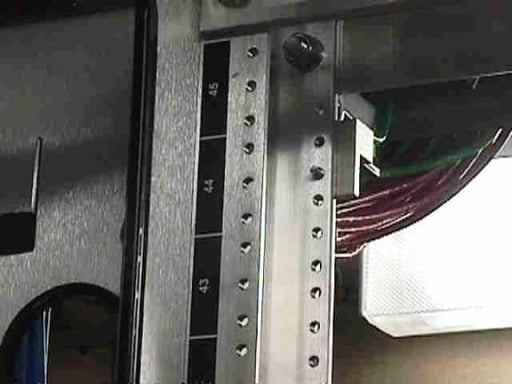
New tower server deployment (3 of 5)
U Designation Strips ensure that all rack-mounted devices are installed according to EIA/TIA rack standards, making rack units easily identifiable, thus eliminating poor space utilization caused by crooked mounting of devices or in a manner that split rack units.
New tower server deployment (4 of 5)
Structured connectivity to various network topologies or applications can be is easily identified by color-coded patch panel ports.
New tower server deployment (5 of 5)
KVM modules use twisted pair cable, instead of bulky, vendor-specific KVM cables thus decreasing cable congestion RJ-45 ports on the KVM switch can be connected through patch panels, enabling remote switch location and more rack space is reserved for tower servers.
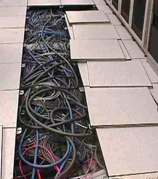
Old cabling methods for raised access floors (1 of 6)
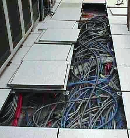
For years, property owners and IT managers have permitted the installation of data cabling under access floors to be performed by network administrators or cabling technicians, not knowing that specific guidelines regarding the cabling methods in these areas are stipulated within various fire and building codes, particularly NFPA-70 the National Electrical Code, strict adherence to which is required by law.
Old cabling methods for raised access floors (2 of 6)
Because access floors are used as pathways for cabling, NEC specifies maximum fill percentage not to exceed 40%. Excess cabling also restricts air flow through the plenum floor, thus creating problems dissipating the excessive heat generated by data center equipment.
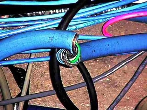
Old cabling methods for raised access floors (3 of 6)
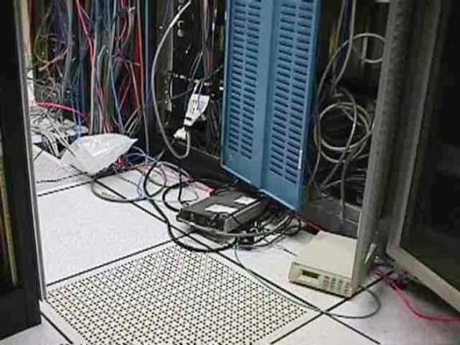
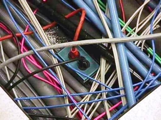
An example of potential fire hazards that often lurk beneath a raised floor. There is live voltage on this circuit’s exposed current-carrying conductors. This was an accident waiting to happen for an unsuspecting technician to possibly come into contact with live voltage while pulling a network cable, or cause the exposed conductors to make contact with a ground source, thus creating an arc, and potentially causing a fire.
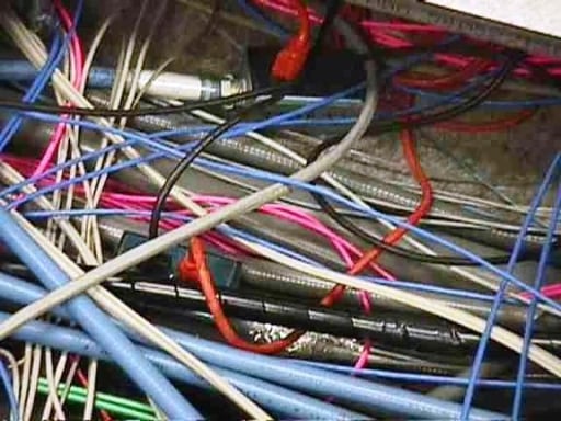
Old cabling methods for raised access floors (4 of 6)
As equipment is replaced, often requiring new cabling to be added, old cables are seldom removed and often abandoned. Inevitably, this practice leads to eventually exceeding the maximum allowable fill percentages.
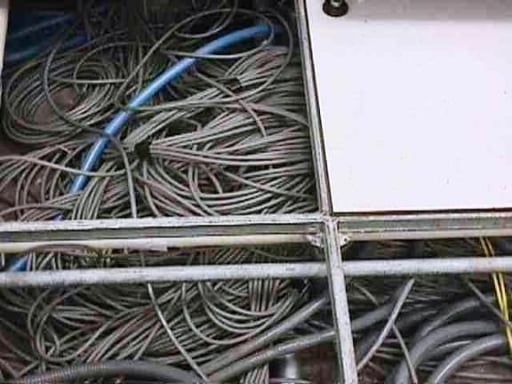
Old cabling methods for raised access floors (5 of 6)
Erratic pathways and installation methods will eventually lead to the virtually impossible task of removing old unused cabling, presenting high risk of accidental impact to network operations and up-time statistics.
Old cabling methods for raised access floors (6 of 6)
Many of the cables installed in this floor are PVC (not plenum rated), which produces extremely toxic smoke during a fire. What’s more, using non-locking electrical plugs and cords increases the risk of fire.
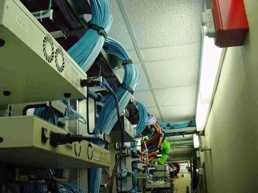
New cabling methods for raised access floors (1 of 4)
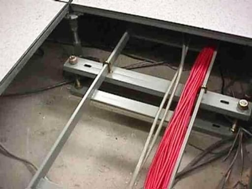
Installing ladder tray beneath raised access floors enables creation of distinct pathways for maintaining the separation of power and data cabling.
New cabling methods for raised access floors (2 of 4)
Where power and data pathways are run parallel to one another, they should occupy alternate rows of the floor grid, with an empty row inserted in between, for maintaining separation between power and data cabling, and also offers the additional benefit of promoting unrestricted airflow of HVAC distribution beneath plenum floors.
New cabling methods for raised access floors (3 of 4)
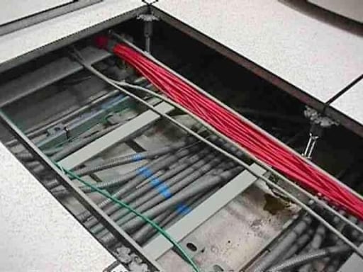
Each pathway should be at a distinct, predefined elevation, eliminating the need for offsets at intersections. Power pathways should be the bottom elevation, while data pathways should be at higher elevations. Where data and power pathways intersect, they should be at 90? relative angles to one another to minimize noise induction.

New cabling methods for raised access floors (4 of 4)
If the raised floor height is low (less than 12 inches deep), there may not be sufficient space for routing both cabling and power, much less for divided elevations. In this case, installing part or all of the data cabling can be installed overhead, thus significantly reducing the raised floor cabling congestion, thus preventing unbalanced distribution of HVAC system due to airflow restrictions. Since under-floor cabling requires use of plenum-rated, overhead installations of pathways offers
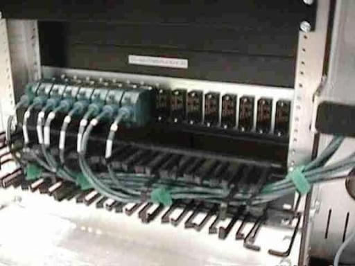
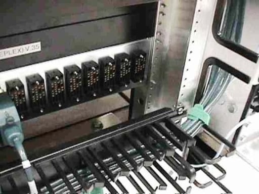
New structured V.35 cabling (1 of 6)
Innovative V-35 Patch Panel
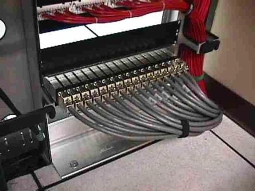
New structured V.35 cabling (2 of 6)
Innovative V-35 Patch Panel
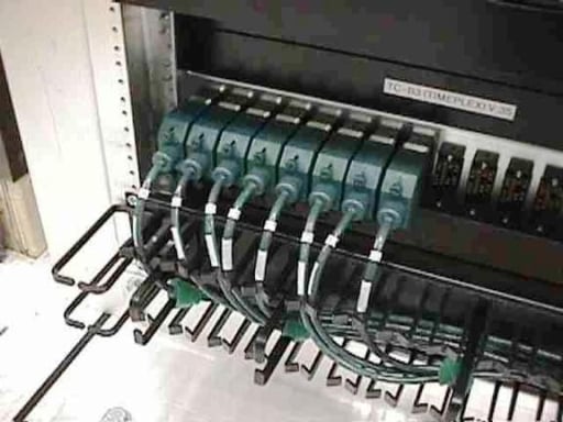
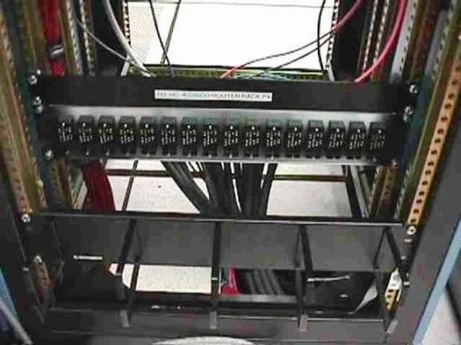
New structured V.35 cabling (3 of 6)
Innovative V-35 Patch Panel
New structured V.35 cabling (4 of 6)
Innovative V-35 Patch Panel
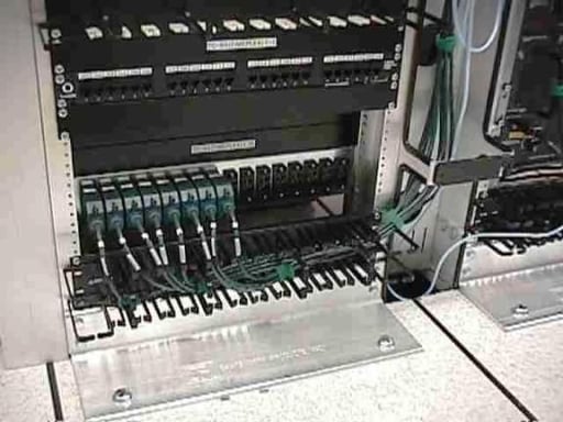
New structured V.35 cabling (5 of 6)
Innovative V-35 Patch Panel
New structured V.35 cabling (6 of 6)
Innovative V-35 Patch Panel
Bill Detwiler is the Editor for Technical Content and Ecosystem at Celonis. He is the former Editor in Chief of TechRepublic and previous host of TechRepublic's Dynamic Developer podcast and Cracking Open, CNET and TechRepublic's popular online show. Previously, Bill was an IT manager in the social research and energy industries. He has bachelor's and master's degrees from the University of Louisville, where he has also lectured on computer crime and crime prevention.


