The Microsoft Kinect is an Xbox 360 peripheral that allows a “controller-free gaming and entertainment experience.” Packed with cameras, microphones, an IR projector, and more, the Kinect is Microsoft’s answer to the Nintendo Wii remote and the Sony Playstation Move controller.
Follow along as I crack open the Kinect for a look at the hardware inside.
Photo by: Bill Detwiler / TechRepublic
Caption by: Bill Detwiler
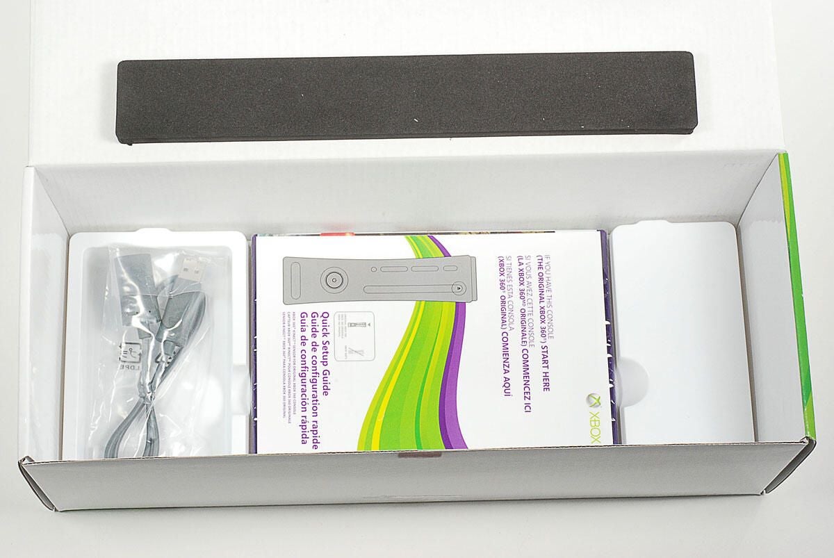
Under the Kinect are the WiFi extension cable, product documentation, and the Kinect Adventures game.
Photo by: Bill Detwiler / TechRepublic
Caption by: Bill Detwiler
Photo by: Bill Detwiler / TechRepublic
Caption by: Bill Detwiler
Thin plastic grills are mounted on both side of the Kinect. They are held in place with adhesive and plastic tabs. Using a thin metal blade or spudger, you can pry each grill loose from the Kinect’s case.
Photo by: Bill Detwiler / TechRepublic
Caption by: Bill Detwiler
Photo by: Bill Detwiler / TechRepublic
Caption by: Bill Detwiler

Two Torx T10 security screws are located under each of the gills.
Photo by: Bill Detwiler / TechRepublic
Caption by: Bill Detwiler
Two more Torx T10 screws are hidden beneath the two Xbox 360 stickers–one on each side.
Photo by: Bill Detwiler / TechRepublic
Caption by: Bill Detwiler
With the Torx T10 security screws removed, you can lift off the top cover.
Photo by: Bill Detwiler / TechRepublic
Caption by: Bill Detwiler
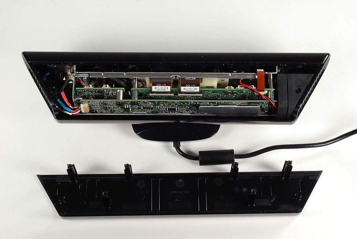
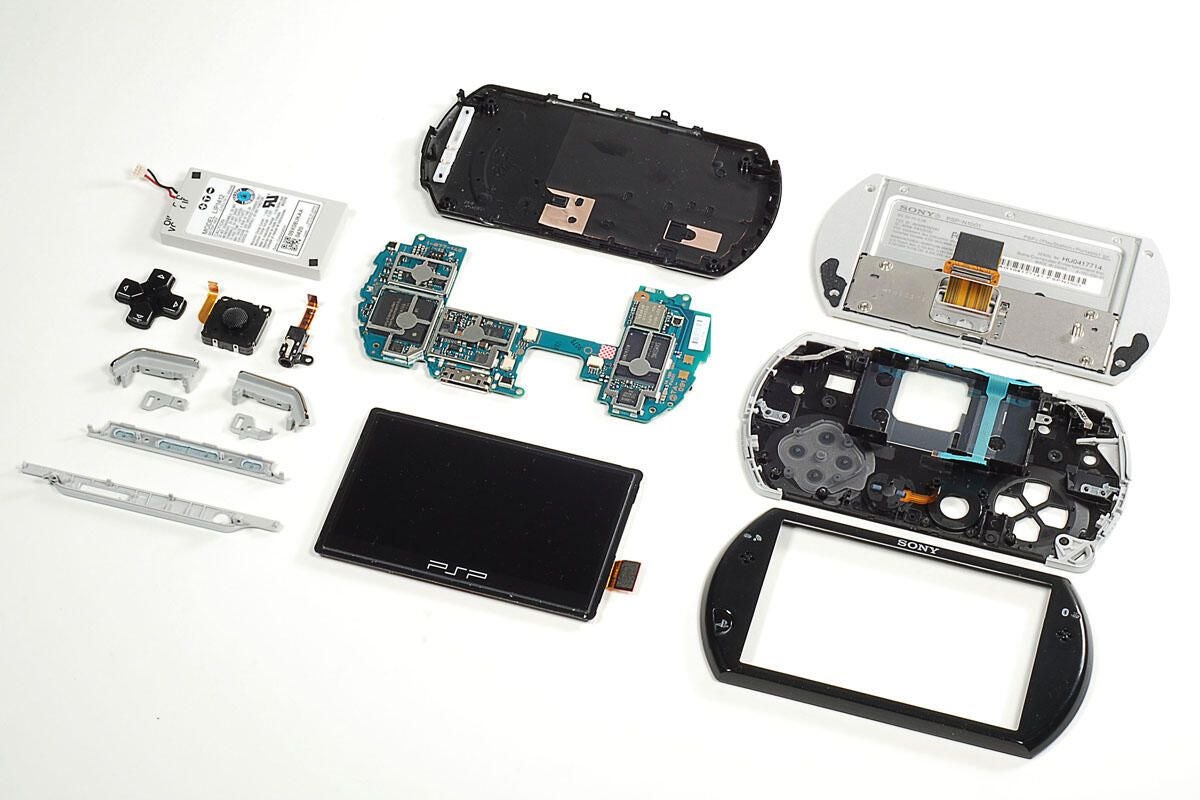
Because of the Kinect’s size, Microsoft stacked the device’s three PCBs.
Photo by: Bill Detwiler / TechRepublic
Caption by: Bill Detwiler
Photo by: Bill Detwiler / TechRepublic
Caption by: Bill Detwiler
With the top cover removed, you can gently slide the right-side grill away from the case.
Photo by: Bill Detwiler / TechRepublic
Caption by: Bill Detwiler
Behind the left-side grill is the Kinect’s cooling fan.
Photo by: Bill Detwiler / TechRepublic
Caption by: Bill Detwiler
Like the right-side grill, you can remove the left-side grill and fan by gently sliding them away from the case. You’ll also need to disconnect the fan’s cable from the PCB.
Photo by: Bill Detwiler / TechRepublic
Caption by: Bill Detwiler
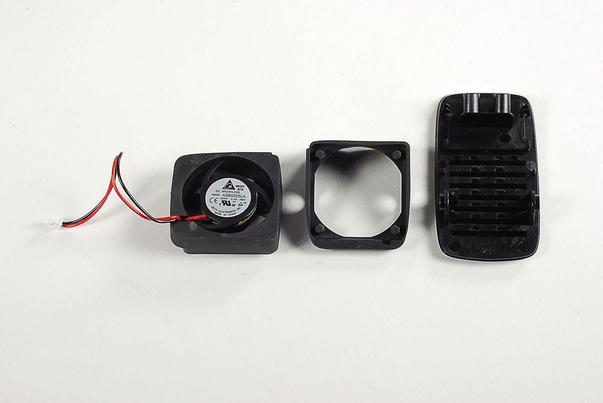
Photo by: Bill Detwiler / TechRepublic
Caption by: Bill Detwiler
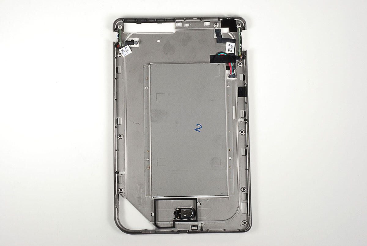
Photo by: Bill Detwiler / TechRepublic
Caption by: Bill Detwiler
The first PCB is held in place by seven Torx T10 screws.
Photo by: Bill Detwiler / TechRepublic
Caption by: Bill Detwiler
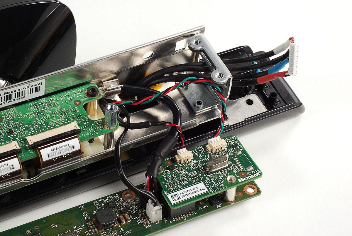
The second, smaller PCB will remain attached to the first PCB, when the larger board is removed from the frame. Several cables connect various components to the first and second PCBs.
Photo by: Bill Detwiler / TechRepublic
Caption by: Bill Detwiler
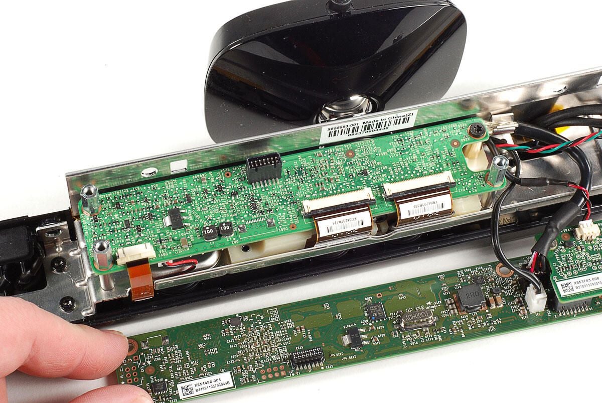
Photo by: Bill Detwiler / TechRepublic
Caption by: Bill Detwiler
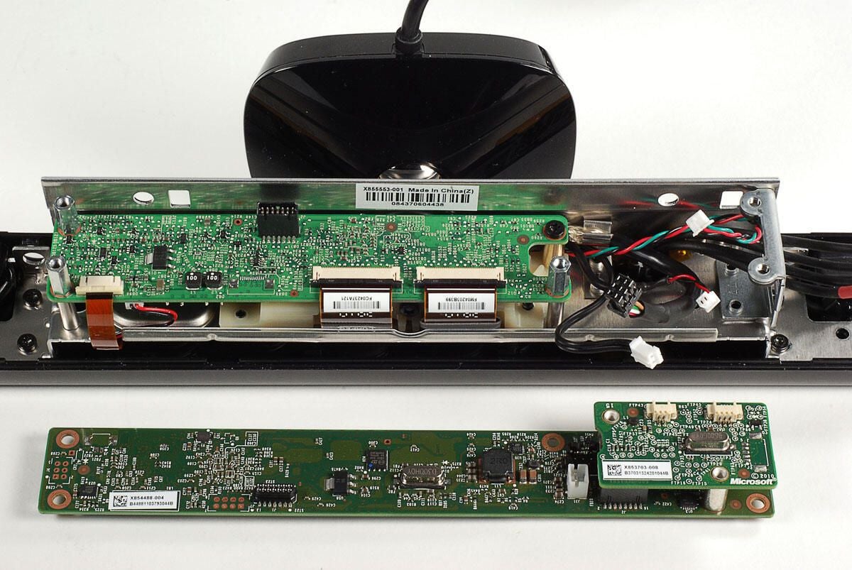
Photo by: Bill Detwiler / TechRepublic
Caption by: Bill Detwiler
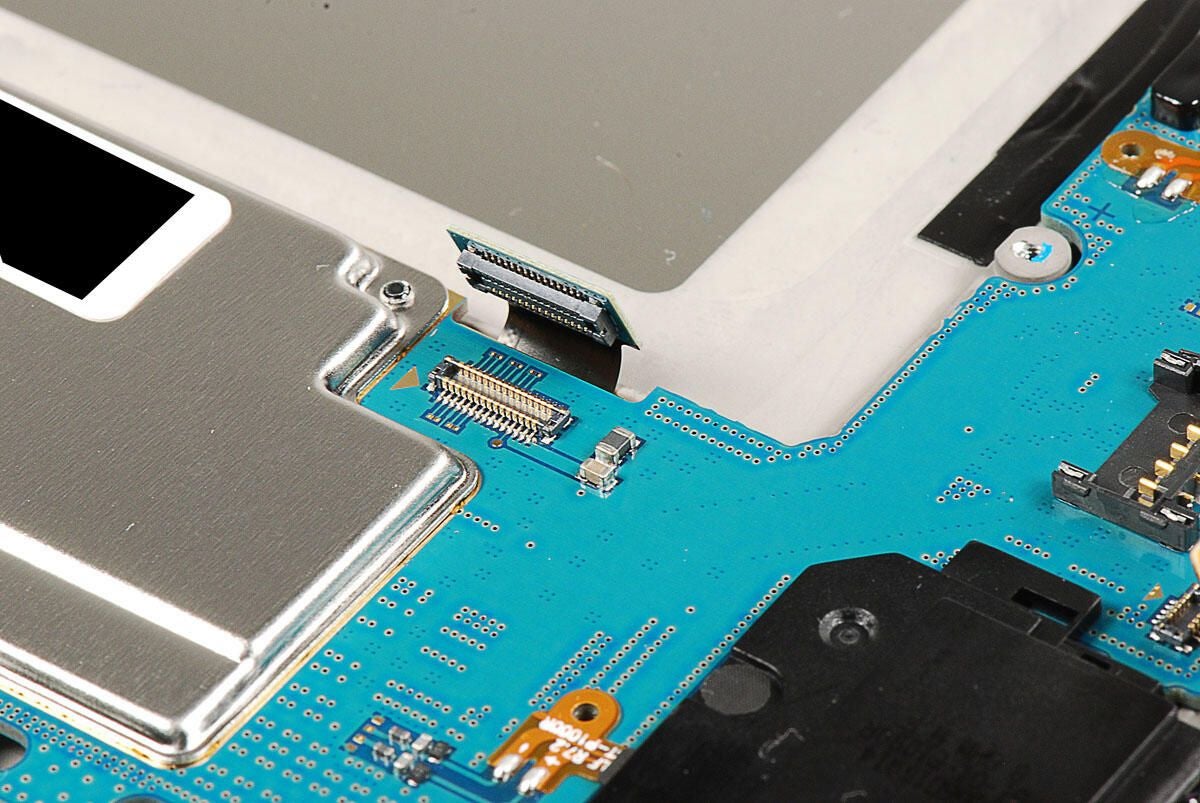
To separate the first and second PCB, you’ll need to pry loose this black, rectangular connector.
Photo by: Bill Detwiler / TechRepublic
Caption by: Bill Detwiler
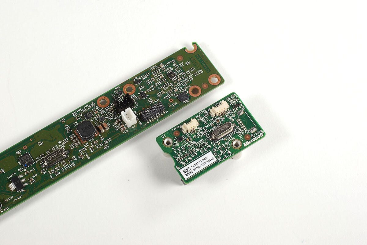
Photo by: Bill Detwiler / TechRepublic
Caption by: Bill Detwiler
A thin metal heat sink is stuck to chips on the first PCB. As I want to put this unit back together in working order, I’m going to leave the heat sink in place.
Photo by: Bill Detwiler / TechRepublic
Caption by: Bill Detwiler
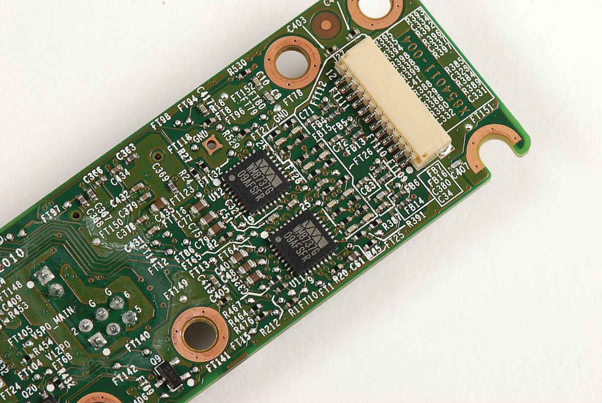
Wolfson Microelectronics WM8737G
Photo by: Bill Detwiler / TechRepublic
Caption by: Bill Detwiler
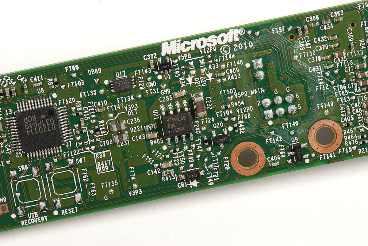
Fairchild Semiconductor FDS8984 (right) and NEC D720114 (left)
Photo by: Bill Detwiler / TechRepublic
Caption by: Bill Detwiler
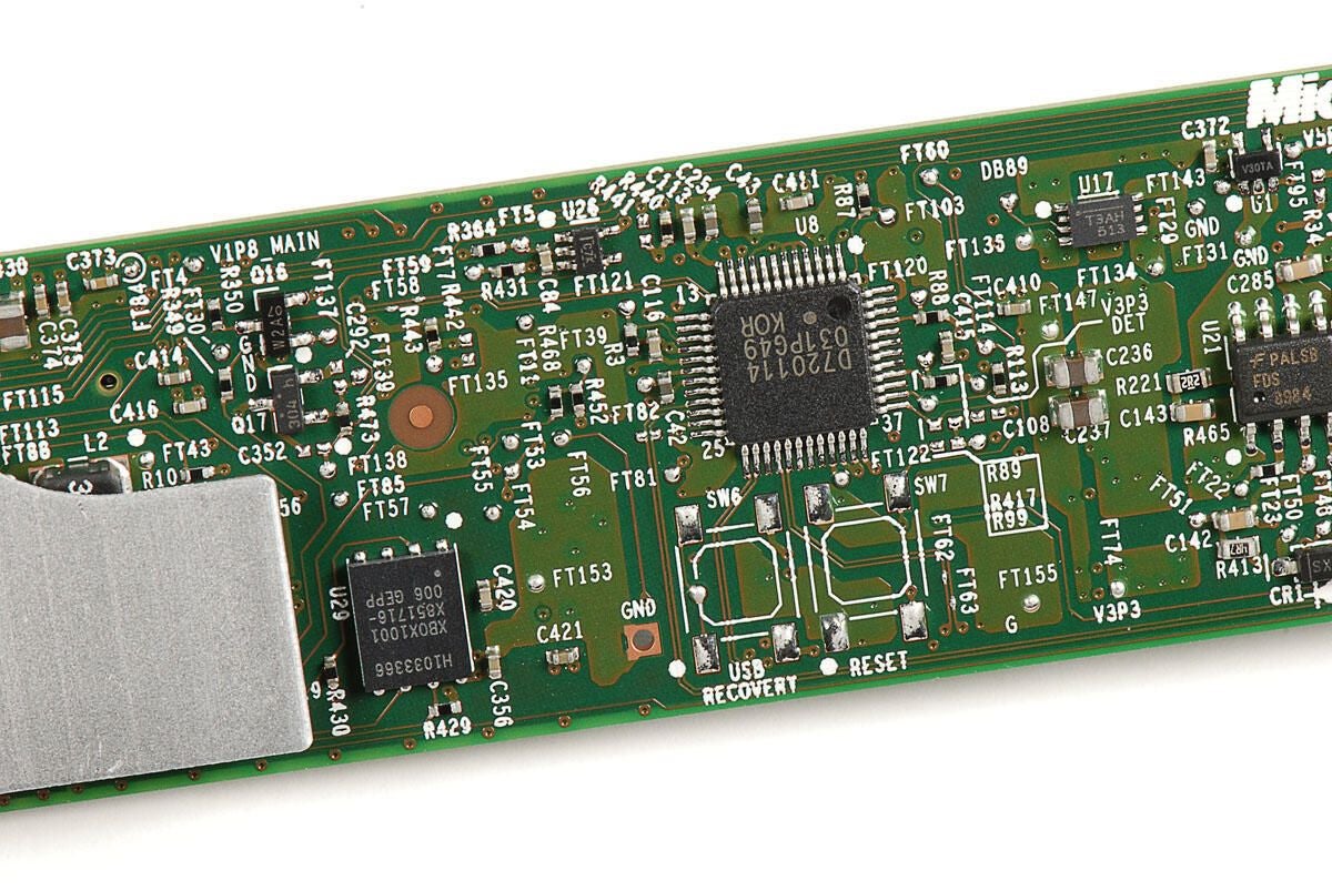
H1033366 XBOX1001 X851716-006 GEPP (left)
Photo by: Bill Detwiler / TechRepublic
Caption by: Bill Detwiler
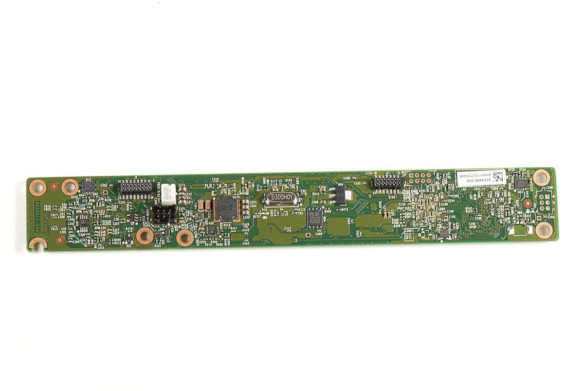
Photo by: Bill Detwiler / TechRepublic
Caption by: Bill Detwiler
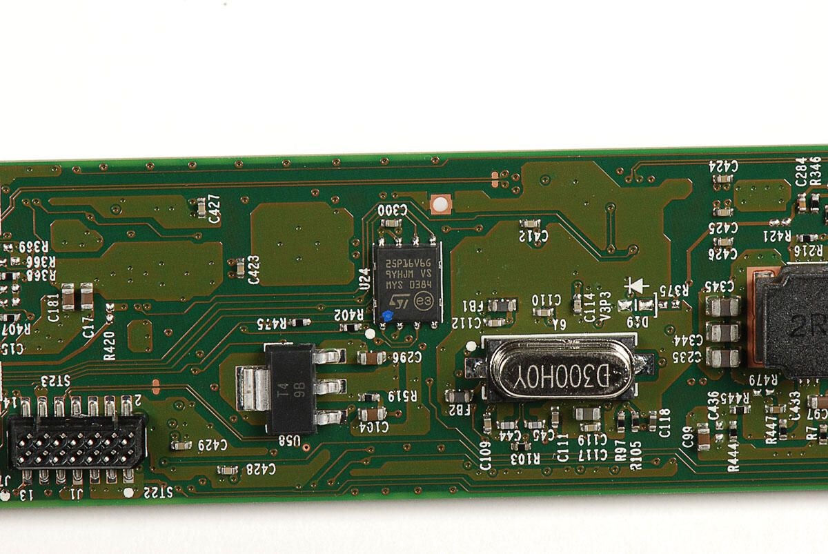
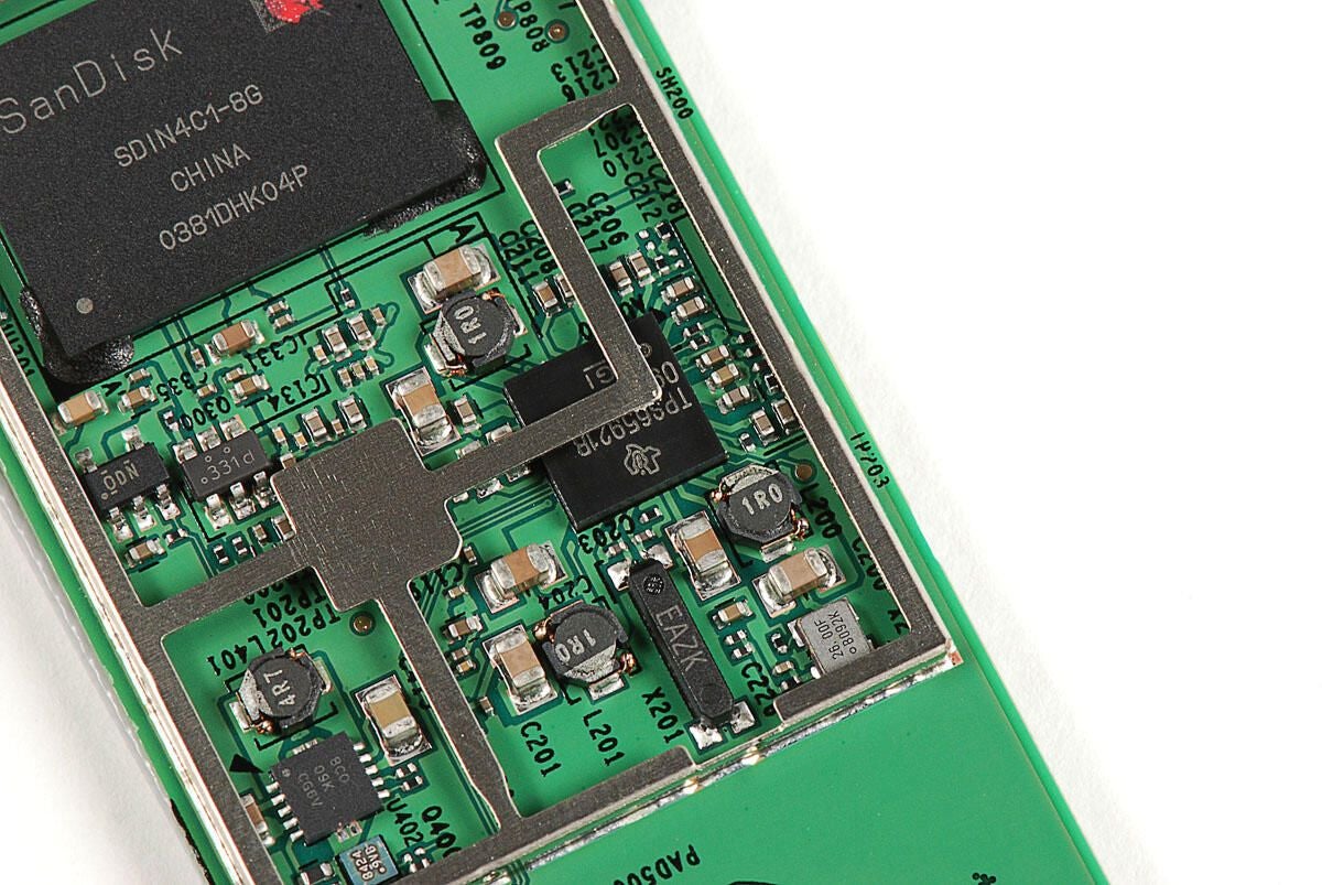
ST Microelectronics 25P16V6G 9YHJM VS MYS 0384
Photo by: Bill Detwiler / TechRepublic
Caption by: Bill Detwiler
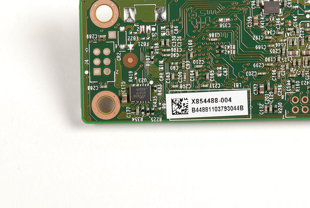
G39 01A1P 025AV
Photo by: Bill Detwiler / TechRepublic
Caption by: Bill Detwiler
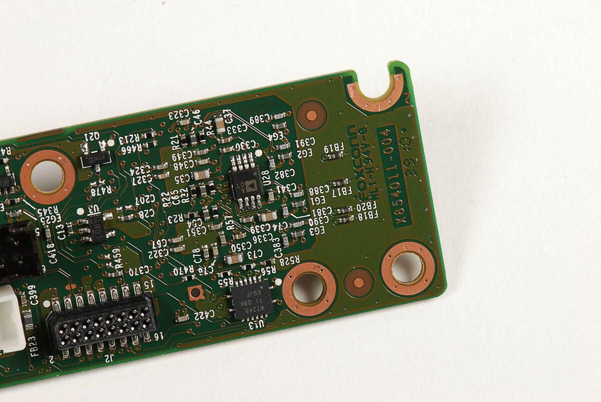
Photo by: Bill Detwiler / TechRepublic
Caption by: Bill Detwiler
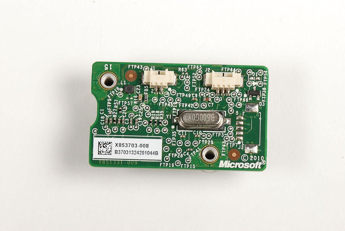
Photo by: Bill Detwiler / TechRepublic
Caption by: Bill Detwiler
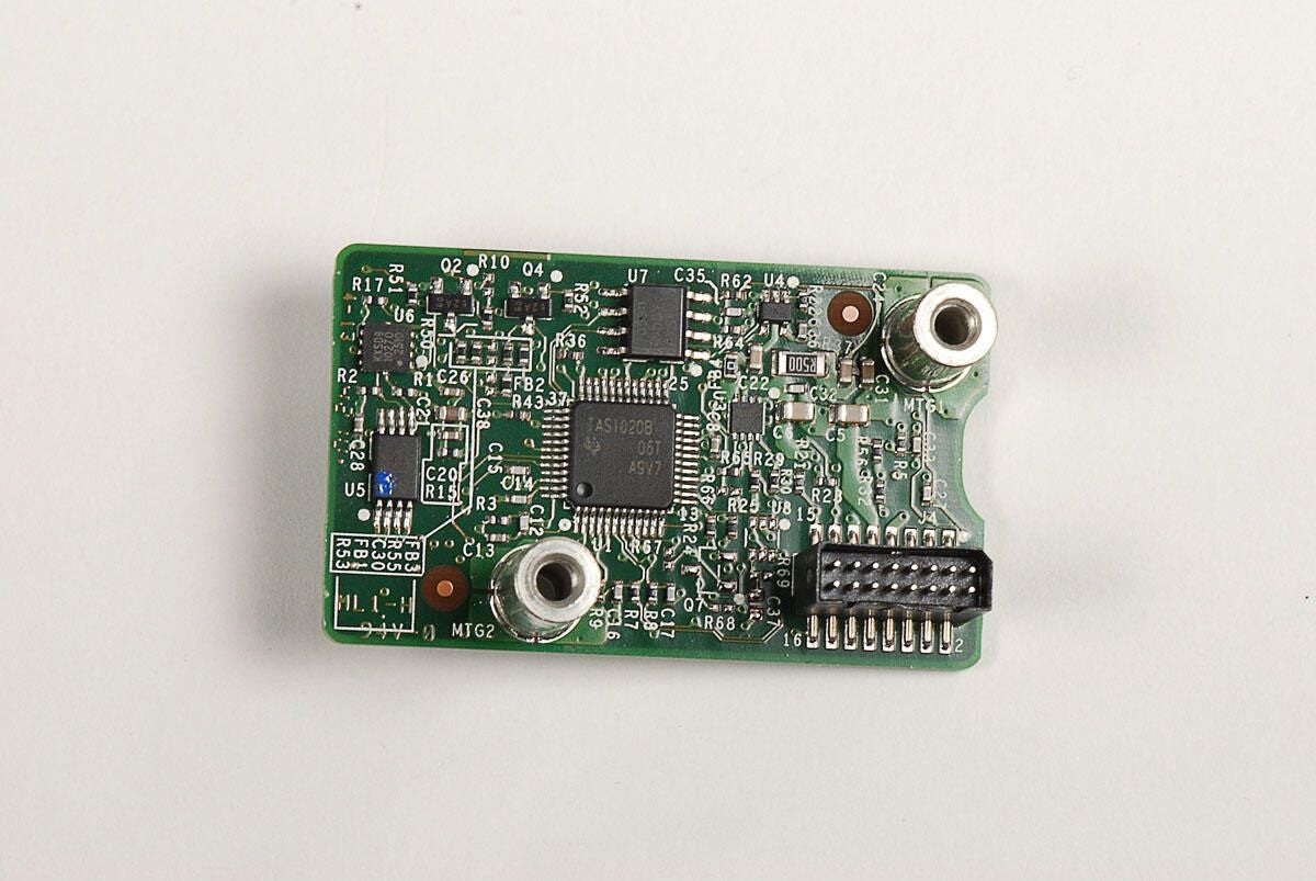
Photo by: Bill Detwiler / TechRepublic
Caption by: Bill Detwiler
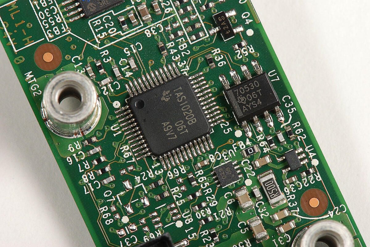
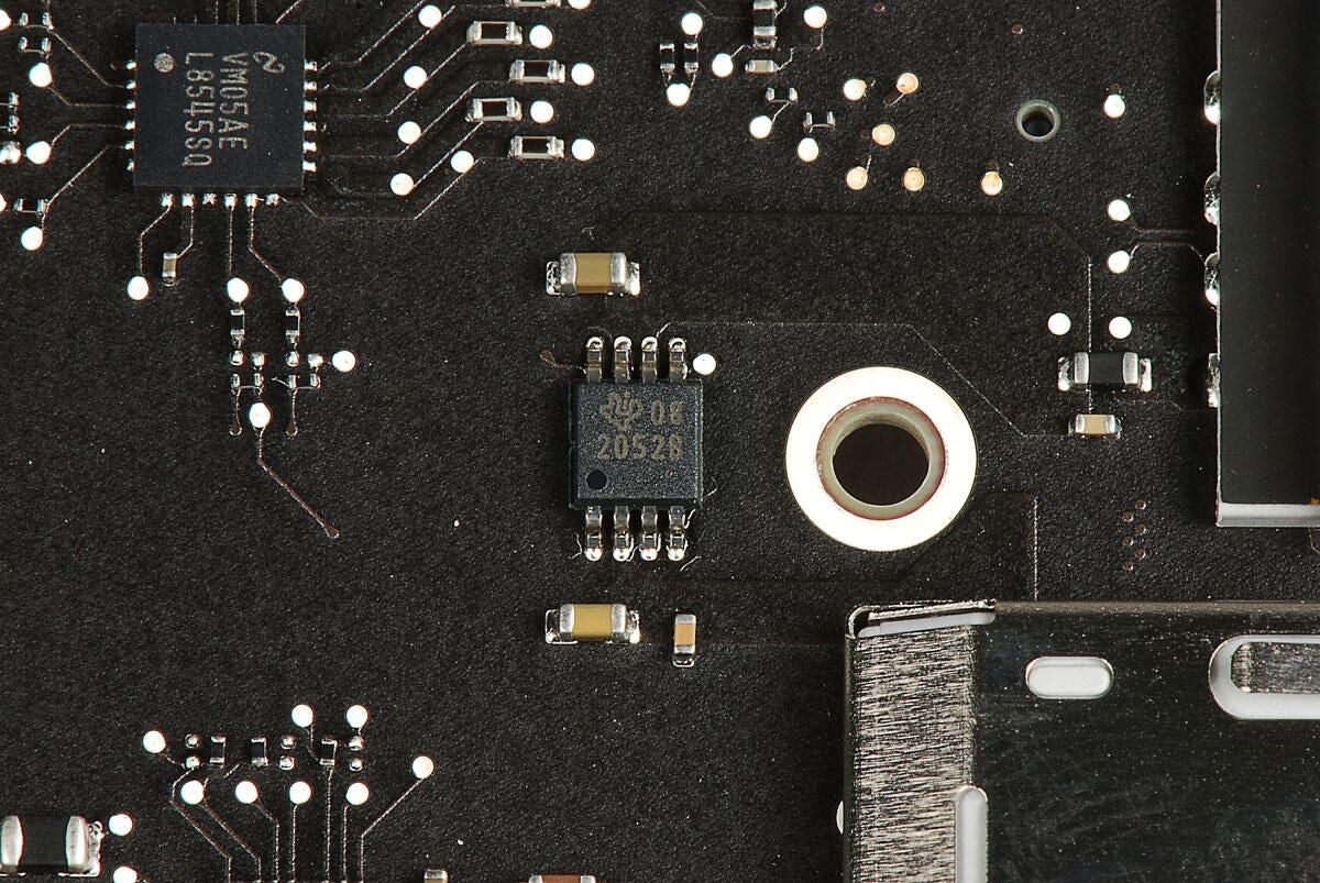
TI TAS1020B
Photo by: Bill Detwiler / TechRepublic
Caption by: Bill Detwiler
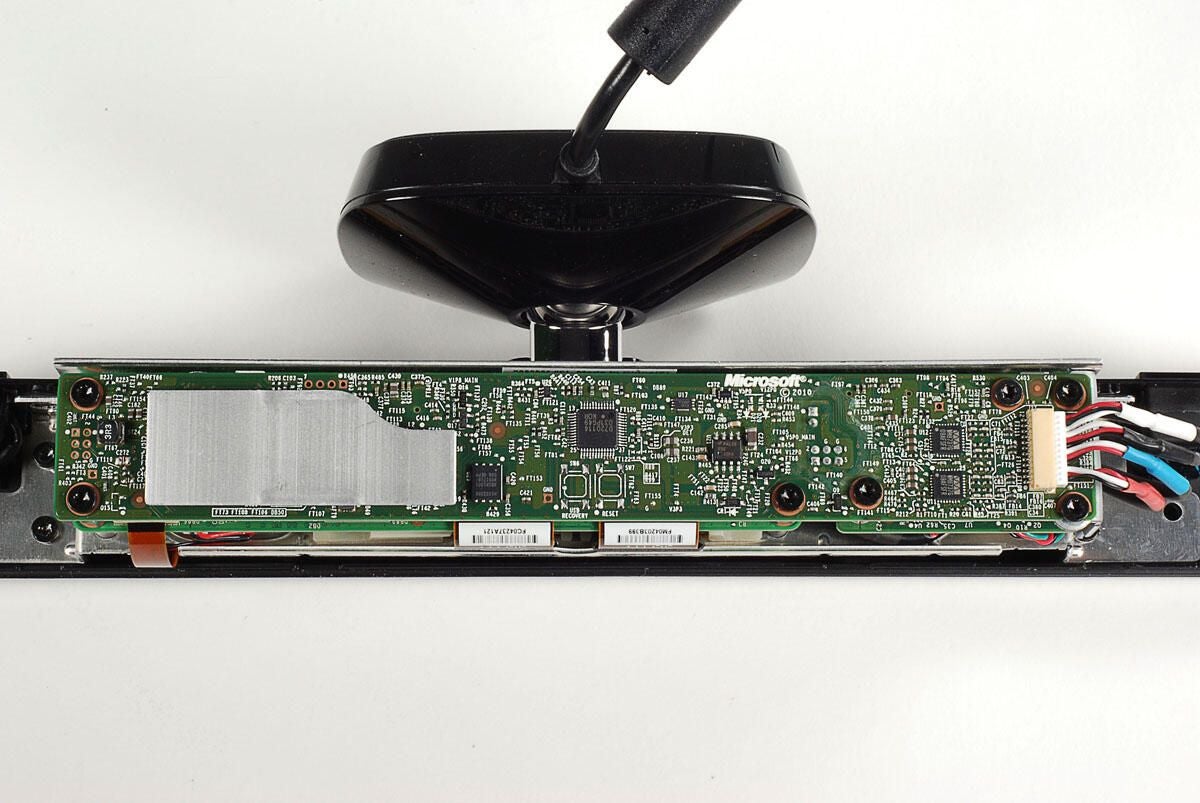
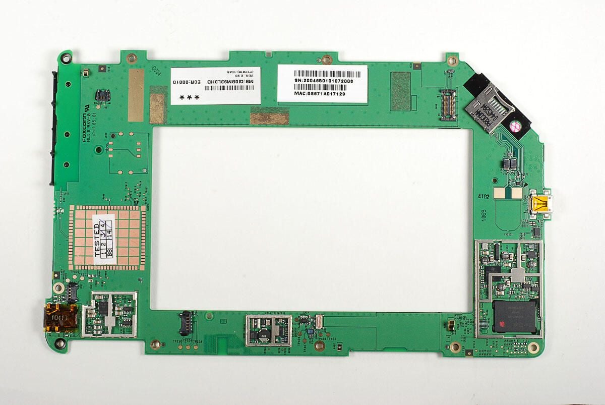
With the first two PCBs removed, we can now tackle the third PCB.
Photo by: Bill Detwiler / TechRepublic
Caption by: Bill Detwiler
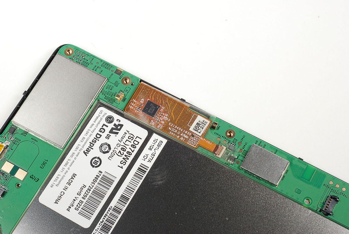
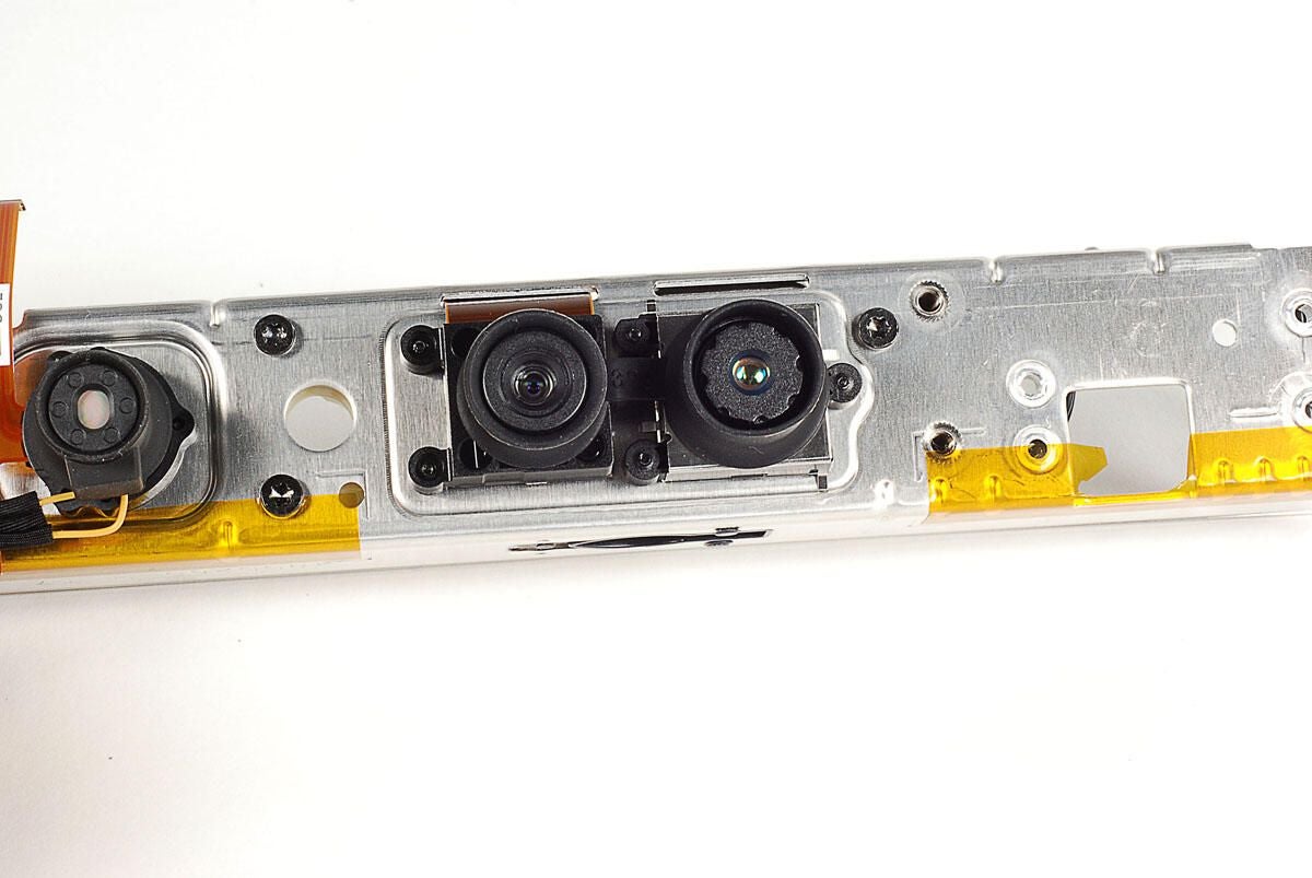
The Kinect’s two cameras and IR projector are connected to the third PCB with three ribbon cables.
Photo by: Bill Detwiler / TechRepublic
Caption by: Bill Detwiler
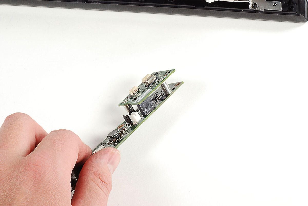
The third PCB is held in place by the posts that were used for the first PCB’s screws. I used a 3/16 inch nut driver to remove them.
Photo by: Bill Detwiler / TechRepublic
Caption by: Bill Detwiler
A single cable is attached to the underside of the third PCB.
Photo by: Bill Detwiler / TechRepublic
Caption by: Bill Detwiler
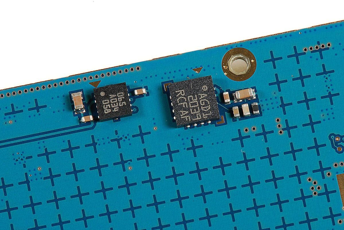
TI ADS 7830I 07NZ
AD8694 A #024 1879325
A3906 1032 262L
Photo by: Bill Detwiler / TechRepublic
Caption by: Bill Detwiler
ST Microelectronics M29W800DB and Prime Sense PS1080
Photo by: Bill Detwiler / TechRepublic
Caption by: Bill Detwiler
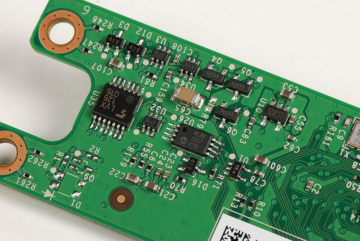
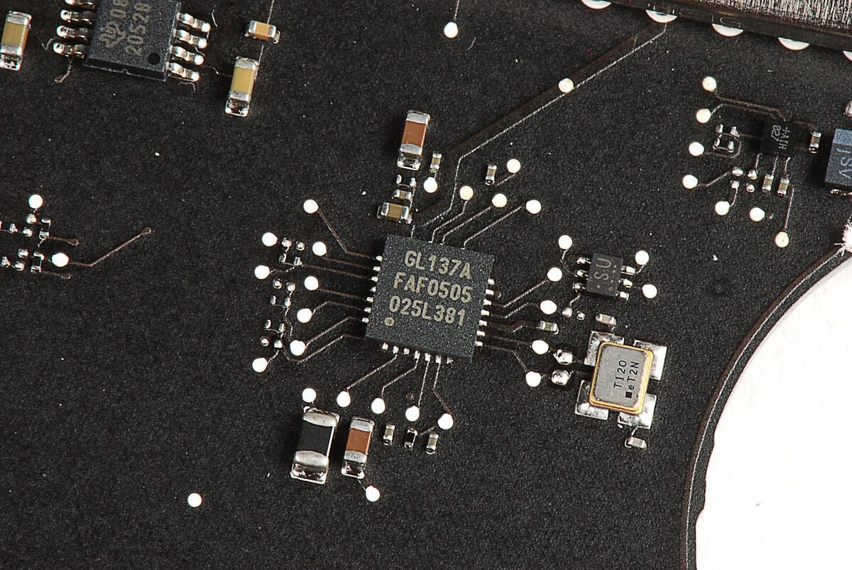
4LBF 1027 K7B and LVX 125 015
Photo by: Bill Detwiler / TechRepublic
Caption by: Bill Detwiler
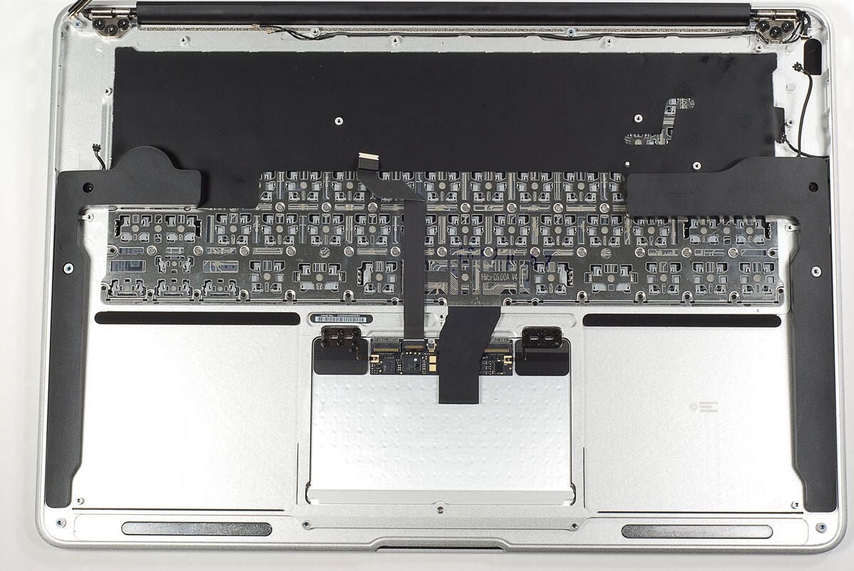
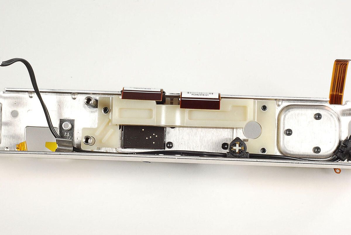
With the Kinect’s three PCBs removed, we can turn our attention to the remaining components.
Photo by: Bill Detwiler / TechRepublic
Caption by: Bill Detwiler
The Kinect’s internal metal frame is held to the front cover with four Torx T10 screws–two on each side.
Photo by: Bill Detwiler / TechRepublic
Caption by: Bill Detwiler
The status LED is held to the front frame with plastic clips. You should be able to remove it without breaking the clips.
Photo by: Bill Detwiler / TechRepublic
Caption by: Bill Detwiler
Once the LED is disconnected, you’ll also need to pull the microphone cable through the frame.
Photo by: Bill Detwiler / TechRepublic
Caption by: Bill Detwiler
Photo by: Bill Detwiler / TechRepublic
Caption by: Bill Detwiler
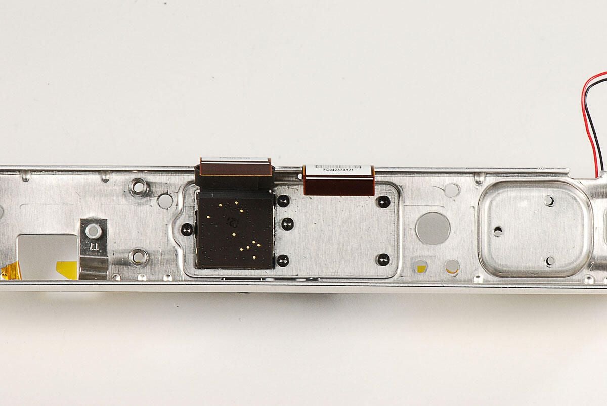
The Kinect has four downward-facing microphones–three on one side and one on the other. All four microphones are attached to a plastic assembly that can be removed from the front cover.
Photo by: Bill Detwiler / TechRepublic
Caption by: Bill Detwiler
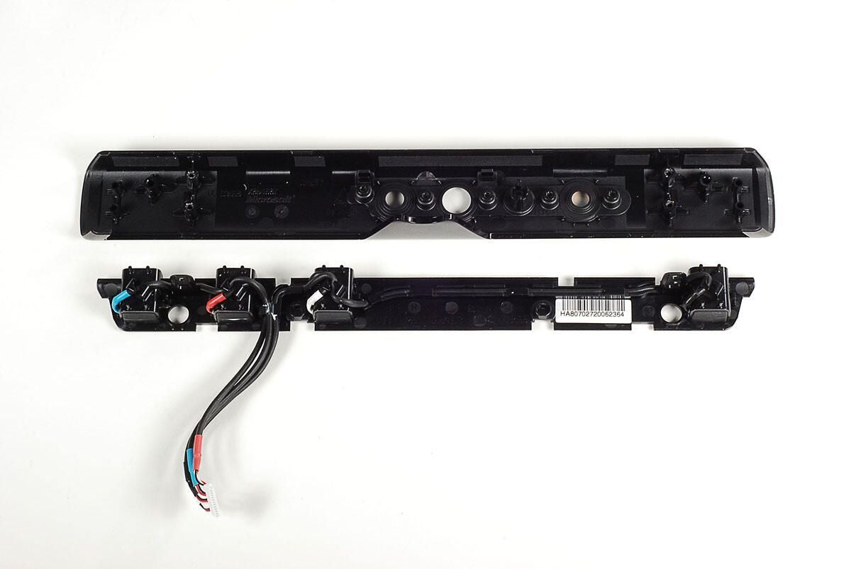
Photo by: Bill Detwiler / TechRepublic
Caption by: Bill Detwiler
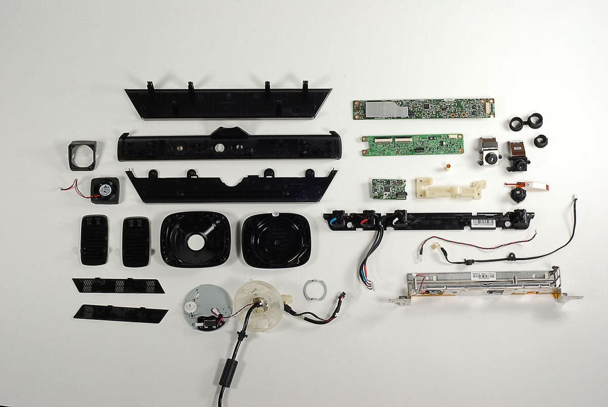
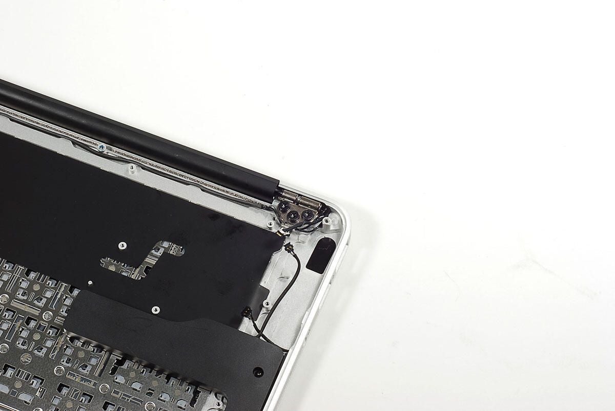
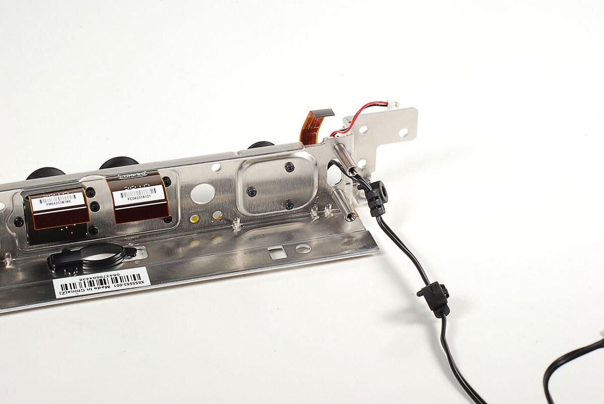
With all the plastic covers and PCBs removed for the Kinect’s main body, all that remains are the cameras, IR projector, status LED, base, and related cables.
Photo by: Bill Detwiler / TechRepublic
Caption by: Bill Detwiler
A single Torx T10 screw holds the base’s post to the metal frame.
Photo by: Bill Detwiler / TechRepublic
Caption by: Bill Detwiler
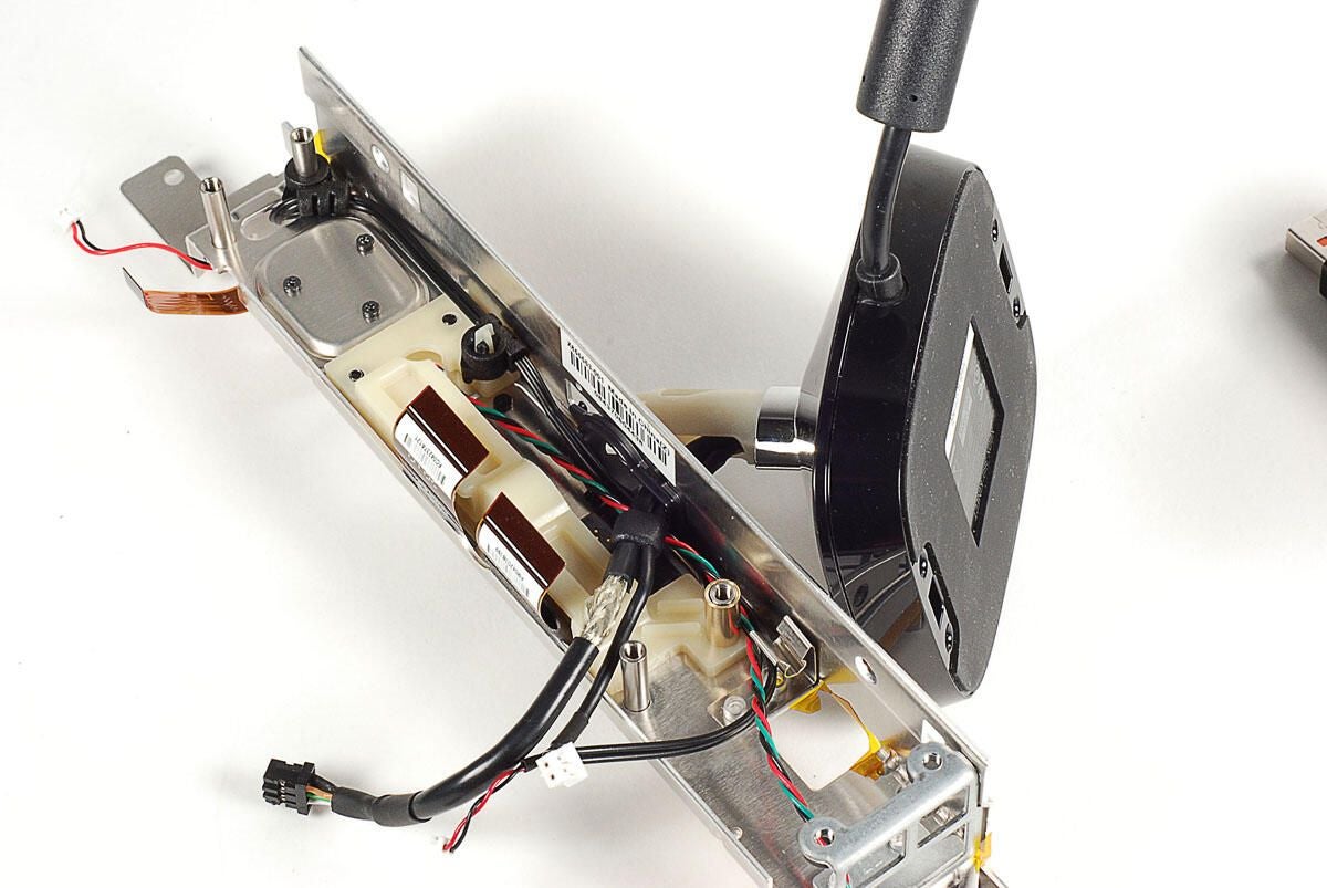
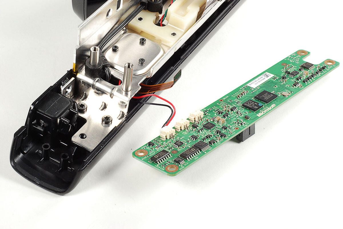
With the post screw removed, you can pull the base away from the metal frame. Take care when pulling the cable through the frame.
Photo by: Bill Detwiler / TechRepublic
Caption by: Bill Detwiler
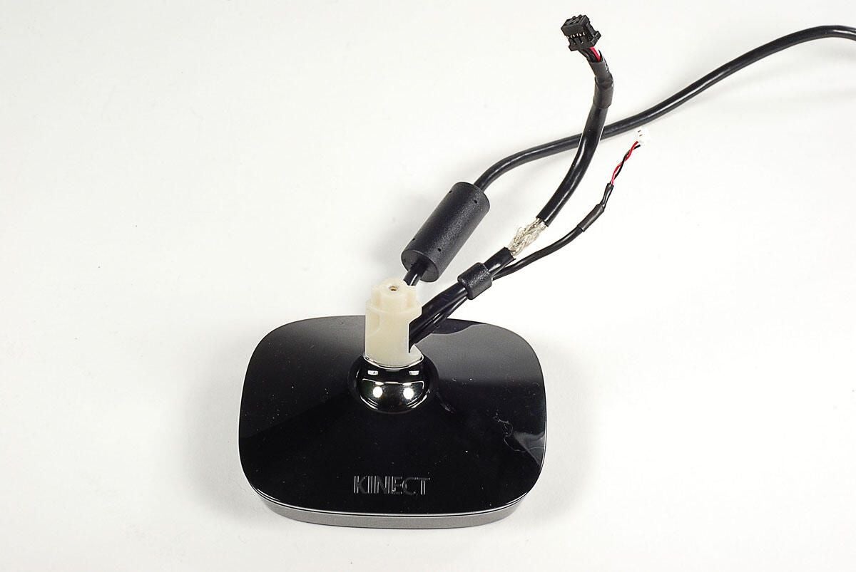
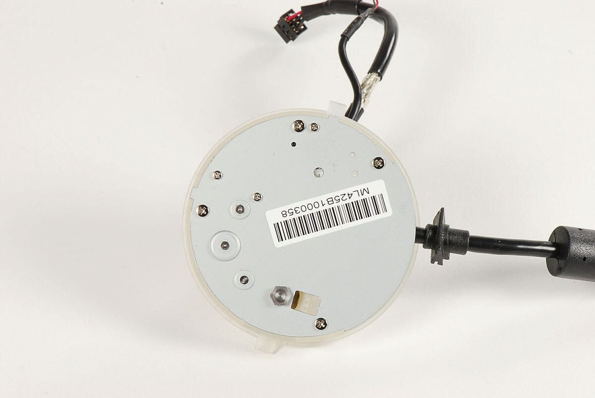
The Kinect’s base contains the motor and gears used to position the device for optimal performance.
Photo by: Bill Detwiler / TechRepublic
Caption by: Bill Detwiler
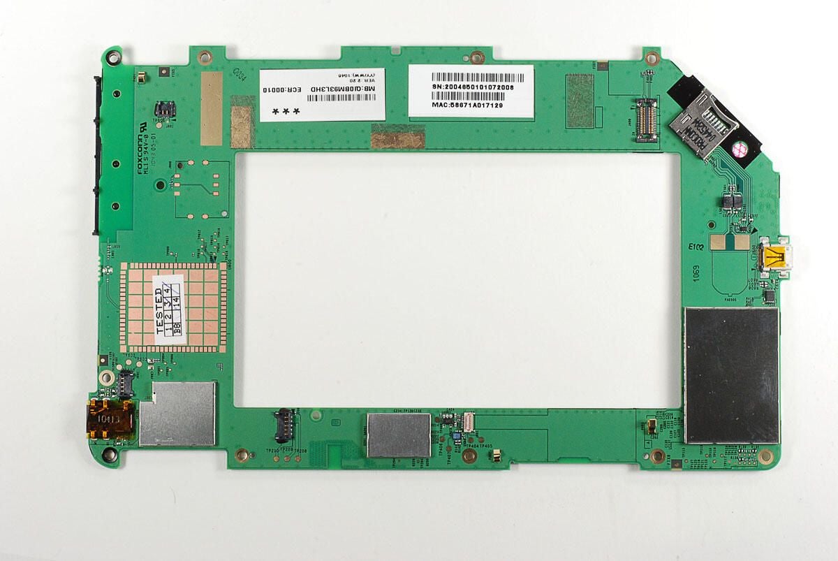
Photo by: Bill Detwiler / TechRepublic
Caption by: Bill Detwiler
Before removing the cameras and IR projector, we’ll remove the white, plastic support that’s mounted to the metal frame.
Photo by: Bill Detwiler / TechRepublic
Caption by: Bill Detwiler
The plastic support is help to the frame by three Torx T10 screws.
Photo by: Bill Detwiler / TechRepublic
Caption by: Bill Detwiler
The cable for the IR projector is attached to the plastic support, you’ll need to remove this before pulling the support completely away from the Kinect.
Photo by: Bill Detwiler / TechRepublic
Caption by: Bill Detwiler
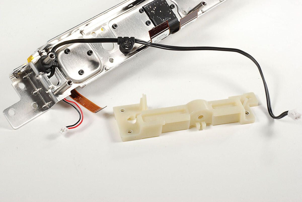
Photo by: Bill Detwiler / TechRepublic
Caption by: Bill Detwiler
The Kinect’s IR projector is attached to the metal frame with three Torx T6 screws.
Photo by: Bill Detwiler / TechRepublic
Caption by: Bill Detwiler
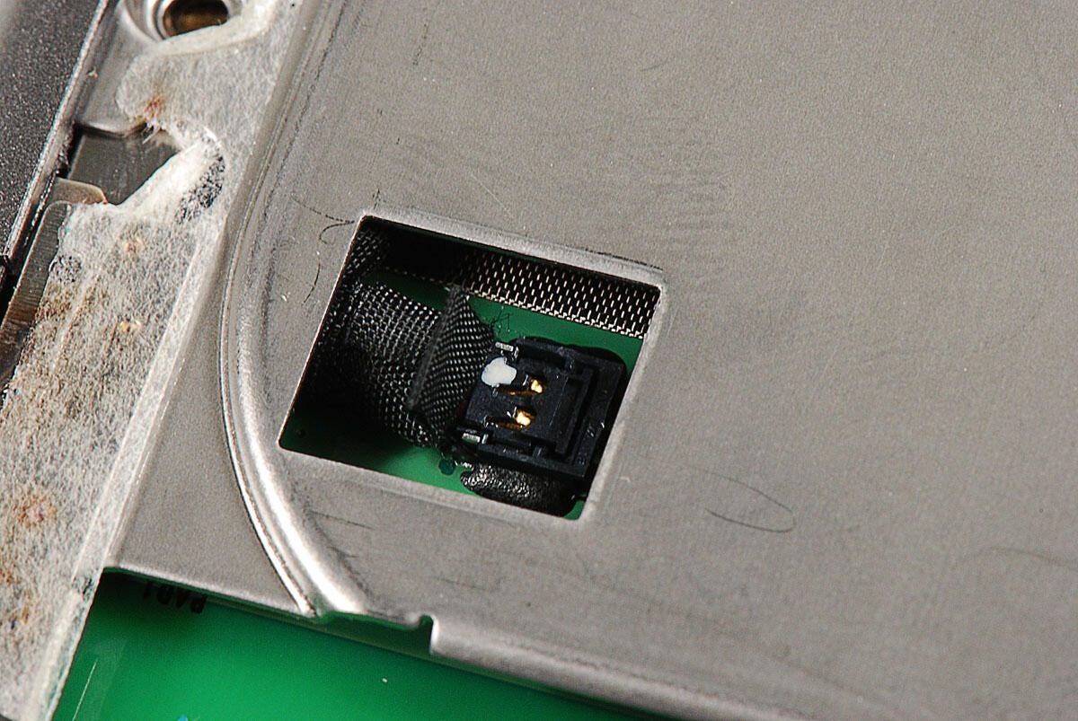
To remove the IR projector from the metal frame, you’ll need to pull the cable through the frame.
When I was removing the cable, I pulled the cable through from the connector end. It wasn’t until after I pulled the cable through, that I find out I could have pulled it through from the other side.
Photo by: Bill Detwiler / TechRepublic
Caption by: Bill Detwiler
Photo by: Bill Detwiler / TechRepublic
Caption by: Bill Detwiler
The Kinect’s IR projector, rubber gasket, and senor cable. Had I removed the rubber gasket, I could have pulled the able through the frame from this end.
Photo by: Bill Detwiler / TechRepublic
Caption by: Bill Detwiler
The Kinect’s two cameras are held to the metal frame with six Torx T6 screws.
Photo by: Bill Detwiler / TechRepublic
Caption by: Bill Detwiler
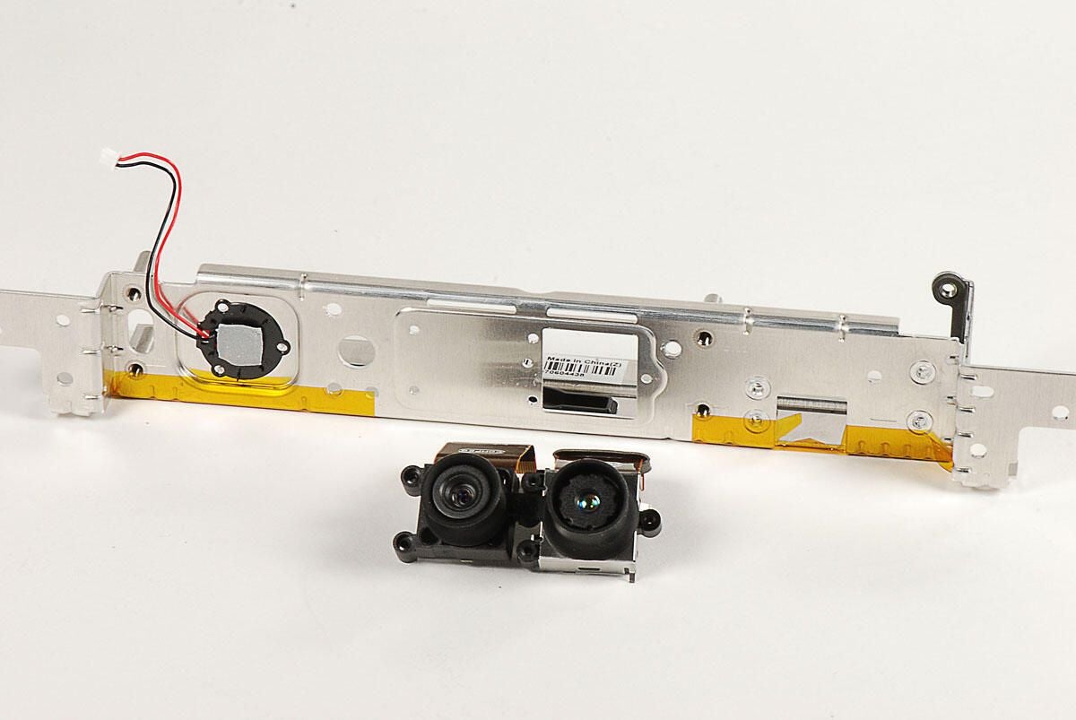
The Kinect’s two cameras are held together with a one-piece rubber gasket.
Photo by: Bill Detwiler / TechRepublic
Caption by: Bill Detwiler
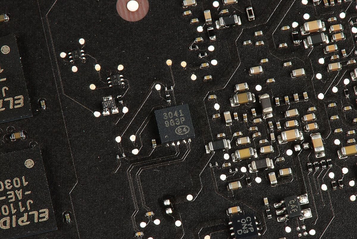
Photo by: Bill Detwiler / TechRepublic
Caption by: Bill Detwiler
A rubber pad is attached to the bottom of the base and hides several Phillips #0 screws.
Photo by: Bill Detwiler / TechRepublic
Caption by: Bill Detwiler
With the Phillips #0 screws removed, you can lift the top cover away from the Kinect’s base.
Photo by: Bill Detwiler / TechRepublic
Caption by: Bill Detwiler
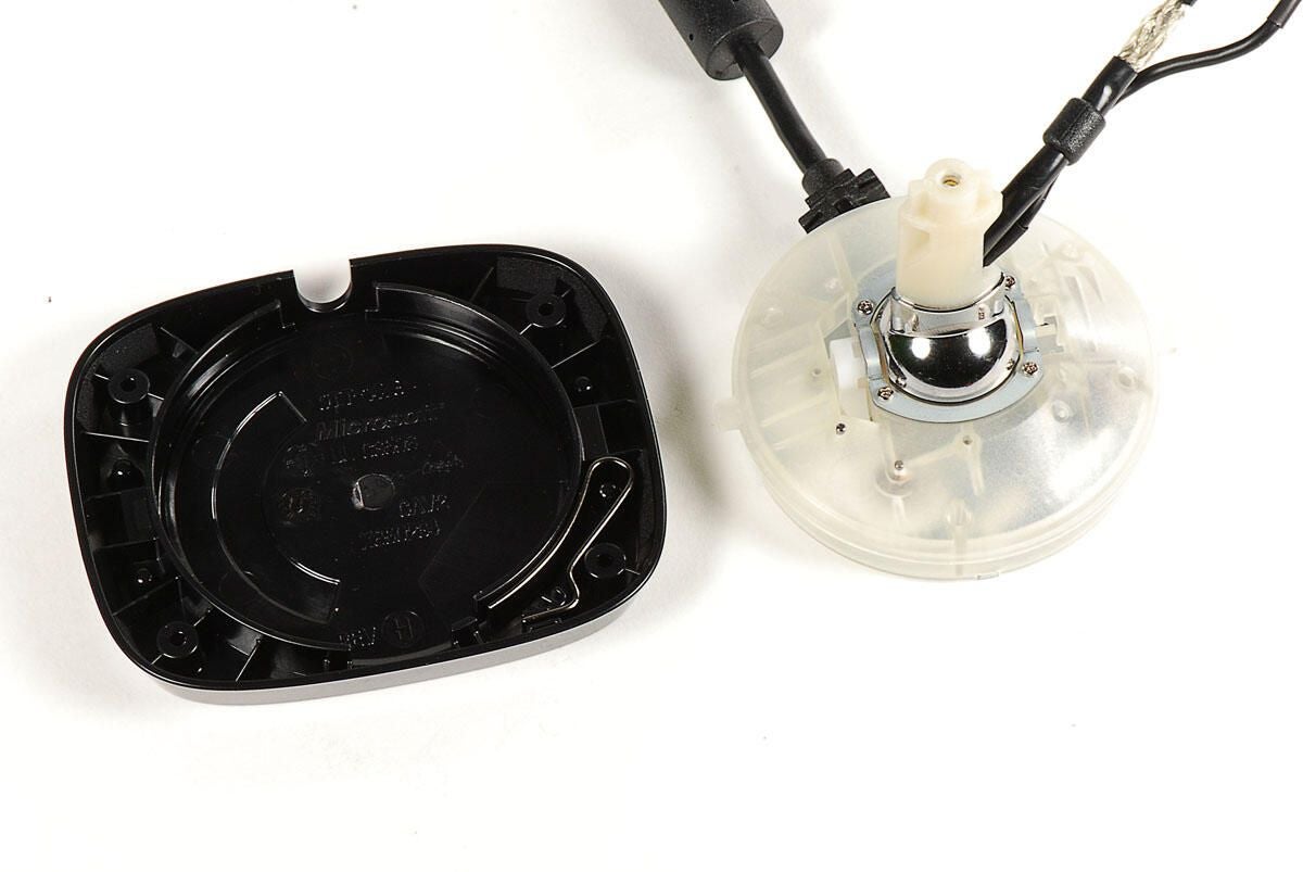
The motor and gear assembly should come right out of the base’s bottom cover.
Photo by: Bill Detwiler / TechRepublic
Caption by: Bill Detwiler
A metal brace holds the post to the motor and gear assembly. The brace is held in place with four Phillips #0 screws.
Photo by: Bill Detwiler / TechRepublic
Caption by: Bill Detwiler
Removing the three large Phillips screws on the bottom of the motor and gear assembly will let open the assembly.
Photo by: Bill Detwiler / TechRepublic
Caption by: Bill Detwiler
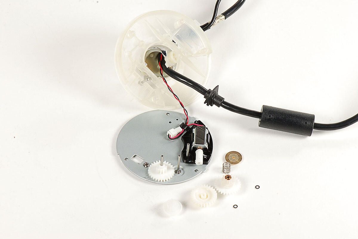
Photo by: Bill Detwiler / TechRepublic
Caption by: Bill Detwiler
Bill Detwiler is the Editor for Technical Content and Ecosystem at Celonis. He is the former Editor in Chief of TechRepublic and previous host of TechRepublic's Dynamic Developer podcast and Cracking Open, CNET and TechRepublic's popular online show. Previously, Bill was an IT manager in the social research and energy industries. He has bachelor's and master's degrees from the University of Louisville, where he has also lectured on computer crime and crime prevention.
