The tech media hasn’t hyped the Samsung Captivate, AT&T’s version of the Galaxy S, as the Motorola Droid 2, the Google Nexus One, or the HTC EVO 4G. But according to TechRepublic’s Jason Hiner, this device stands toe-to-toe with other Android smartphones.
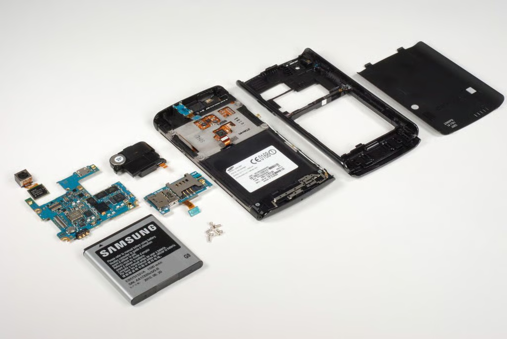
Come along as we crack open the Samsung Captivate for a look at the hardware inside this extremely-capable Android smartphone.
And for a more in-depth comparison of the Captivate to other Android phones, check out Jason’s Product Spotlight review.
Photo credit: Bill Detwiler / TechRepublic
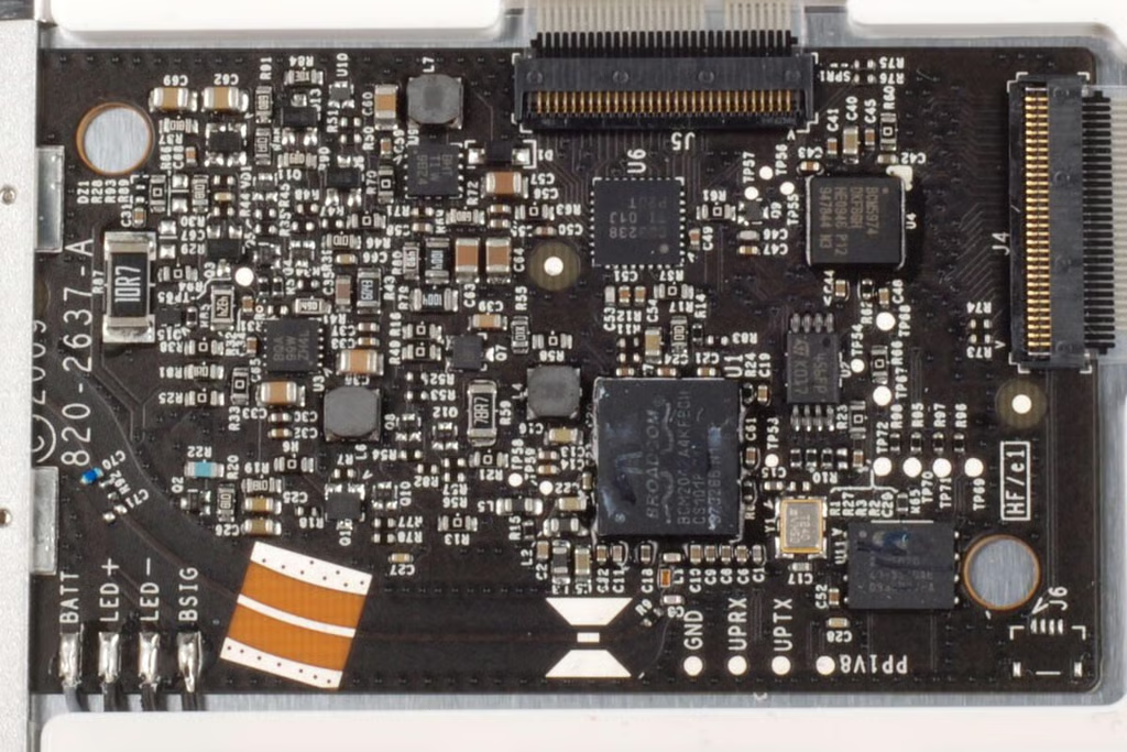
Photo credit: Bill Detwiler / TechRepublic
As this is AT&T’s version of the Samsung Galaxy S, AT&T documentation is included with the Captivate.
Photo credit: Bill Detwiler / TechRepublic
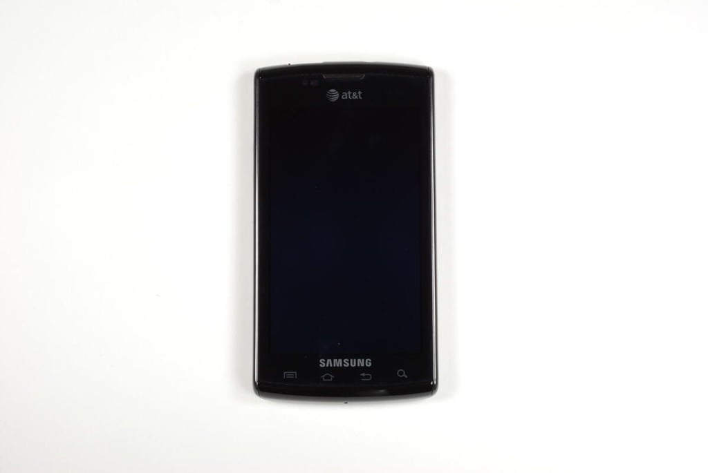
On the front of the Samsung Captivate, you’ll find the external speaker (top), Menu key, Home key, Back key, and Search key (bottom).
Photo credit: Bill Detwiler / TechRepublic
On the back of the Samsung Captivate are the camera, external speaker, and removable cover.
Photo credit: Bill Detwiler / TechRepublic
On the Samsung Captivate’s left side is the volume button.
Photo credit: Bill Detwiler / TechRepublic
The Lock button is located on the right side of the Samsung Captivate. Using this key you can lock and unlock the phone’s display.
Photo credit: Bill Detwiler / TechRepublic
The main microphone is located on the bottom of the Samsung Captivate.
Photo credit: Bill Detwiler / TechRepublic
The 3.5mm headphone jack and Micro-USB charging/data port are located on the top of the Samsung Captivate.
Photo credit: Bill Detwiler / TechRepublic
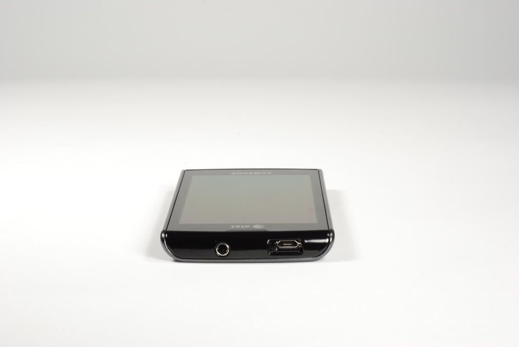
The Samsung Captivate’s Micro-USB port is covered by a sliding door. This photo shows the door in the open position.
Photo credit: Bill Detwiler / TechRepublic
To remove the Samsung Captivate’s back cover, slide the bottom portion of the phone down and lift the cover away from the case.
Photo credit: Bill Detwiler / TechRepublic
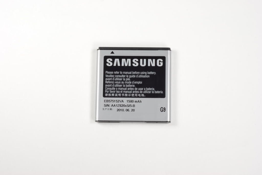
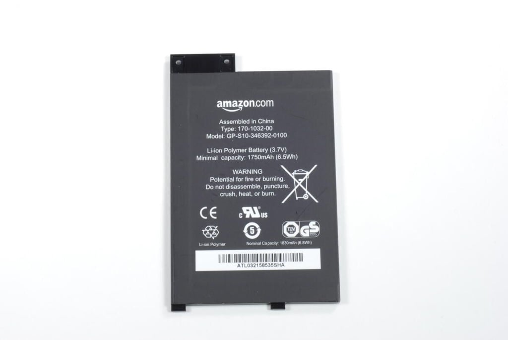
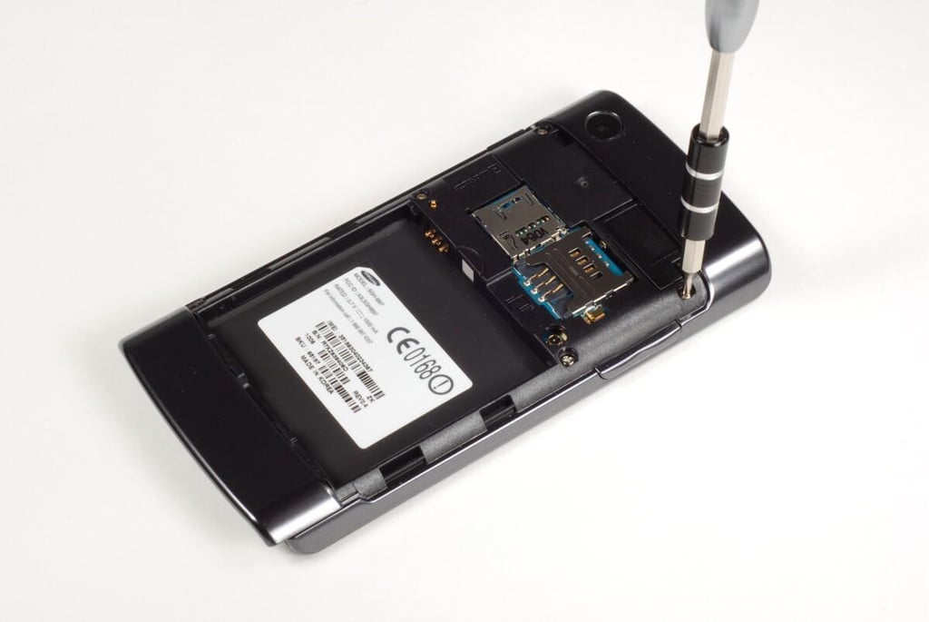
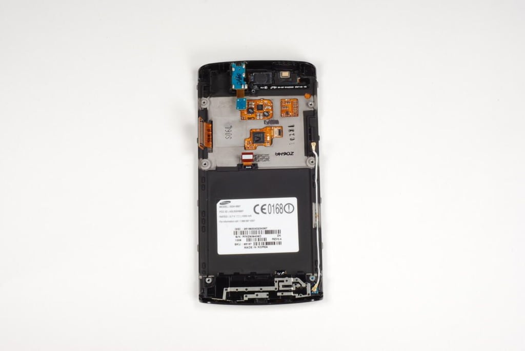
The Samsung Captivate used a 3.7V Lithium-ion battery with 1500 mAh capacity.
Photo credit: Bill Detwiler / TechRepublic
Photo credit: Bill Detwiler / TechRepublic
Six Phillips #000 screws hold the Samsung Captivate’s case to the screen assembly. The first four are clearly visible on the top half of the case. The last two are hidden beneath the sliding portion of the case.
Photo credit: Bill Detwiler / TechRepublic
One Phillips #000 screw is located on each side of the phone, under the sliding portion back cover.
Photo credit: Bill Detwiler / TechRepublic
I tried for several minutes to remove the sliding portion of the Captivate’s back cover, but it didn’t want to come off. Afraid I would break the slider, I decided the best way to access each of the hidden screws was to slide one side of the movable latch down and keep the other side in the closed position.
Photo credit: Bill Detwiler / TechRepublic
With just one side of the movable latch in the open position, I could remove the hidden screw on that side. I repeated the process on the other side to remove the last hidden screw.
Photo credit: Bill Detwiler / TechRepublic
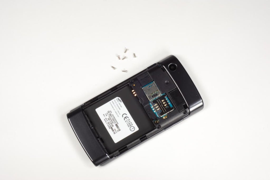
Photo credit: Bill Detwiler / TechRepublic
With a very thin metal spudger, I was able to gently pry the plastic case away from the screen assembly. I started at the bottom of the case and slowly worked my way around.
Photo credit: Bill Detwiler / TechRepublic
Small plastic tabs hold the case to the screen assembly. There are several on each side. You should be able to release all the tabs without breaking the case or the screen assembly.
Photo credit: Bill Detwiler / TechRepublic
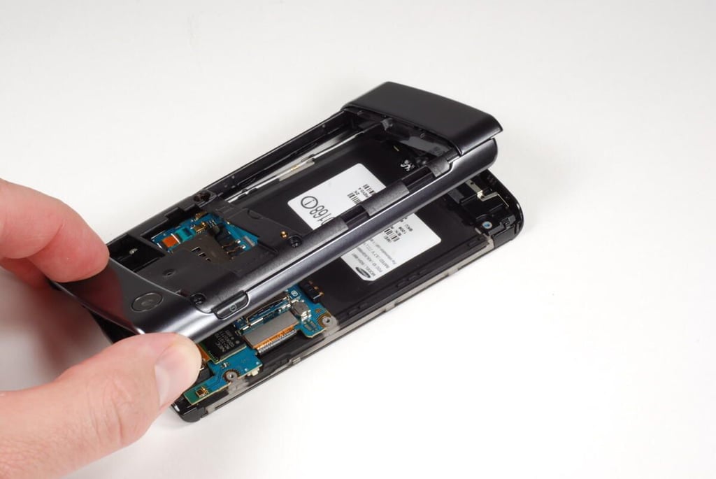
Photo credit: Bill Detwiler / TechRepublic
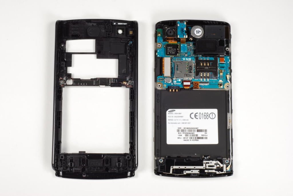
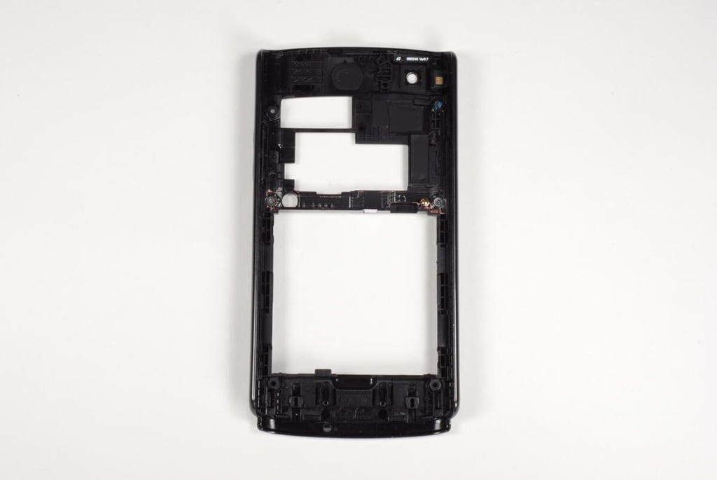
Photo credit: Bill Detwiler / TechRepublic
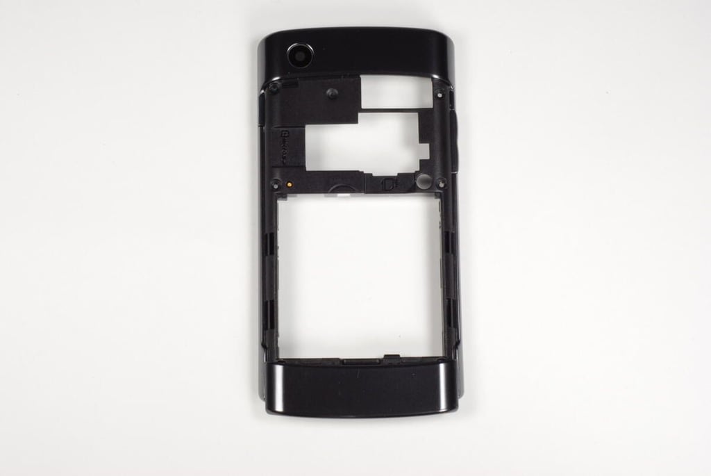
Photo credit: Bill Detwiler / TechRepublic
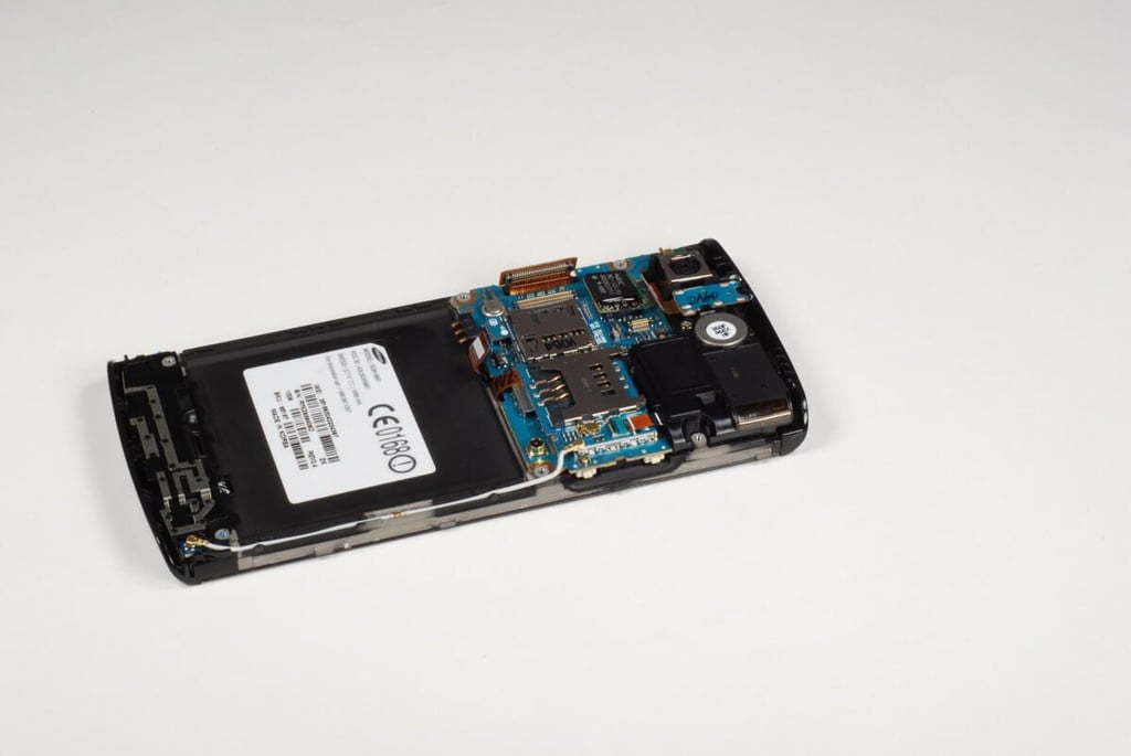
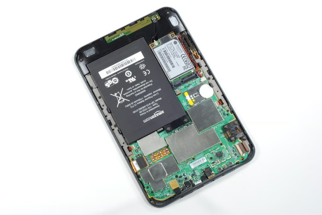
The next step in disassembling the Samsung Captivate is to disconnect all the visible connectors and cables from the main PCB. This will allow us to remove the phone’s various components and the main PCB.
Photo credit: Bill Detwiler / TechRepublic
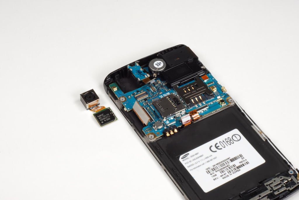
With the camera disconnected from the main PCB, it will simply fall away from the phone’s screen assembly.
Photo credit: Bill Detwiler / TechRepublic
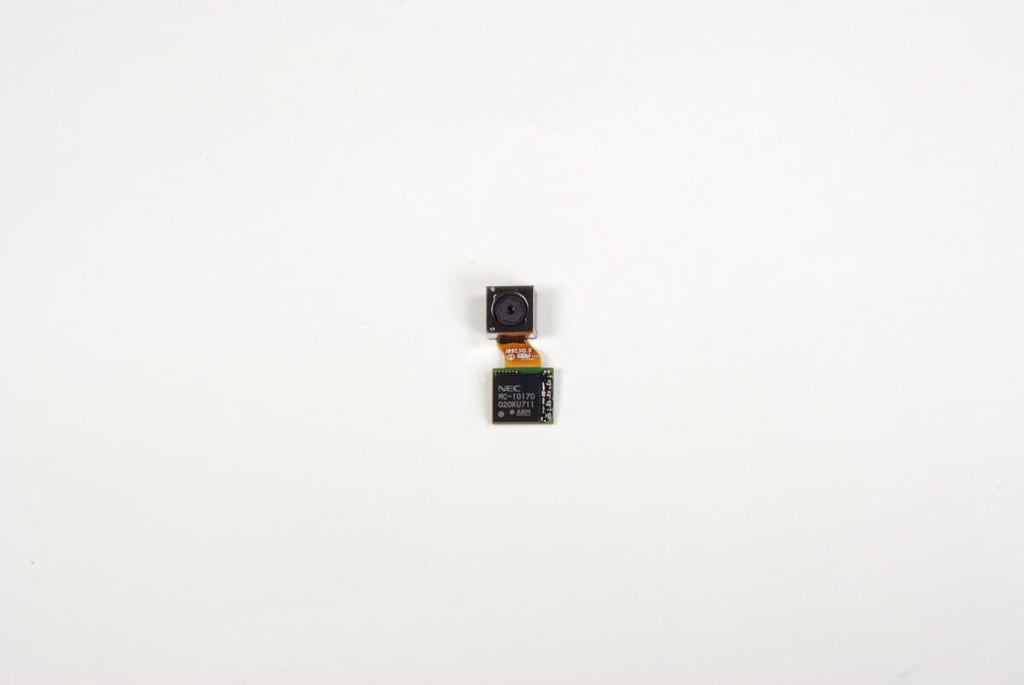
The Samsung Captivate has a 5.0 megapixel with 4x digital zoom and auto-focus. Connected to the camera is a chip with the folloring markings:
NEC
MC-10170
020KU711
ARM
This chip is likely an image processing IC.
Photo credit: Bill Detwiler / TechRepublic
Photo credit: Bill Detwiler / TechRepublic
A single Phillips #000 screw holds the main PCB to the screen assembly.
Photo credit: Bill Detwiler / TechRepublic
With the seventh screw removed, we can lift the Samsung Captivate’s main PCB away from the screen assembly.
Photo credit: Bill Detwiler / TechRepublic
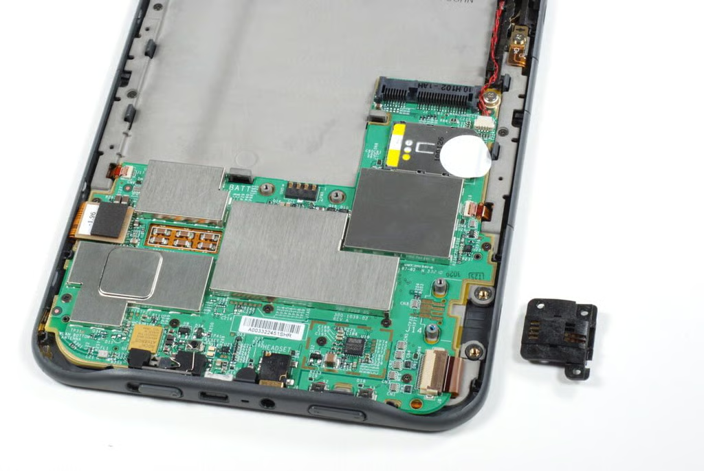
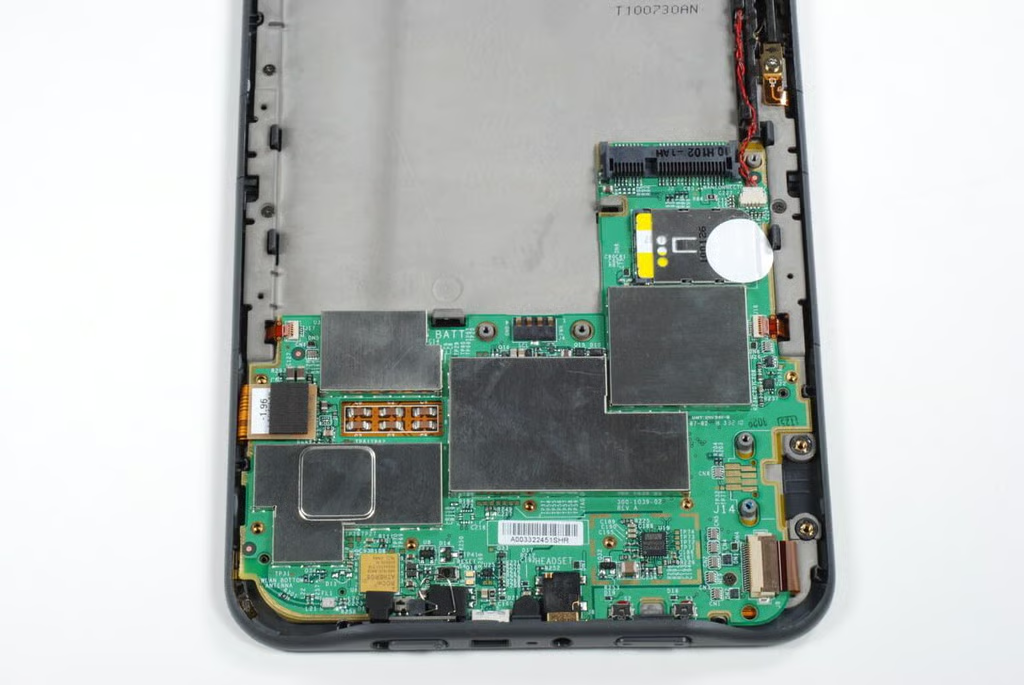
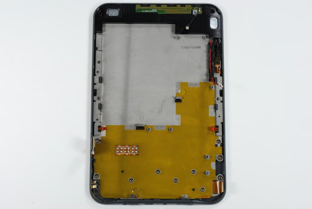
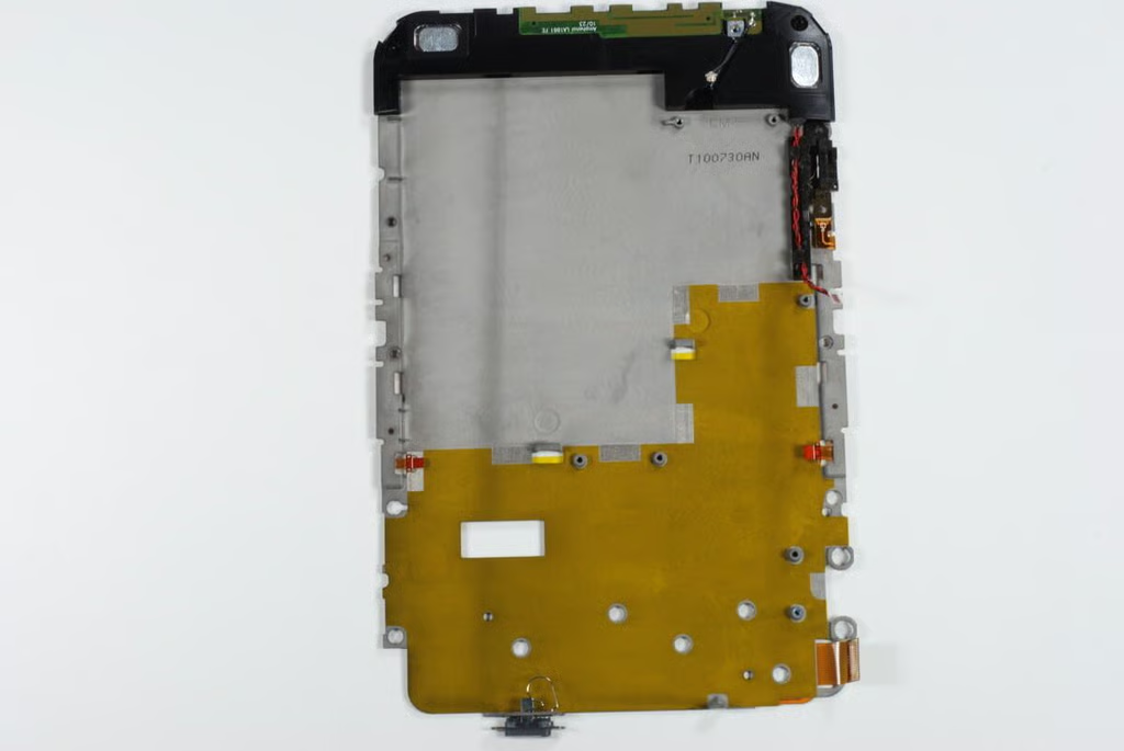
This photo shows the screen assembly with the main PCB removed.
Photo credit: Bill Detwiler / TechRepublic
Along the bottom of the screen assembly are the connectors for the four buttons on the front screen and the antenna cable.
Photo credit: Bill Detwiler / TechRepublic
Along the top of the screen assembly are the 3.5mm headphone jack, ambient light sensor, and proximity sensor. Mounted to the back of the display is an ATMEL TSP touch control IC.
Photo credit: Bill Detwiler / TechRepublic
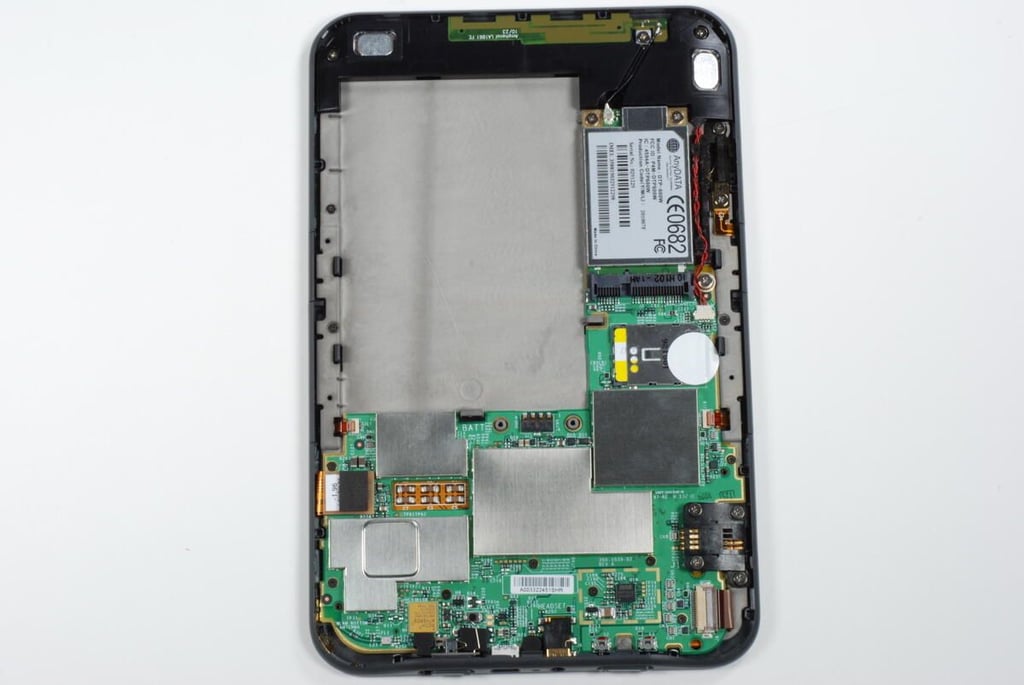
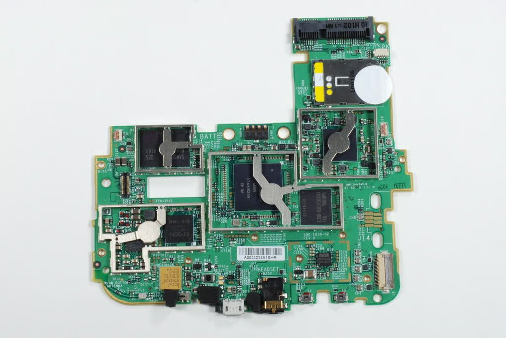
This photo shows the Samsung Captivate’s main PCB with speaker assembly and SD/SIM card slot PCB still attached.
Photo credit: Bill Detwiler / TechRepublic
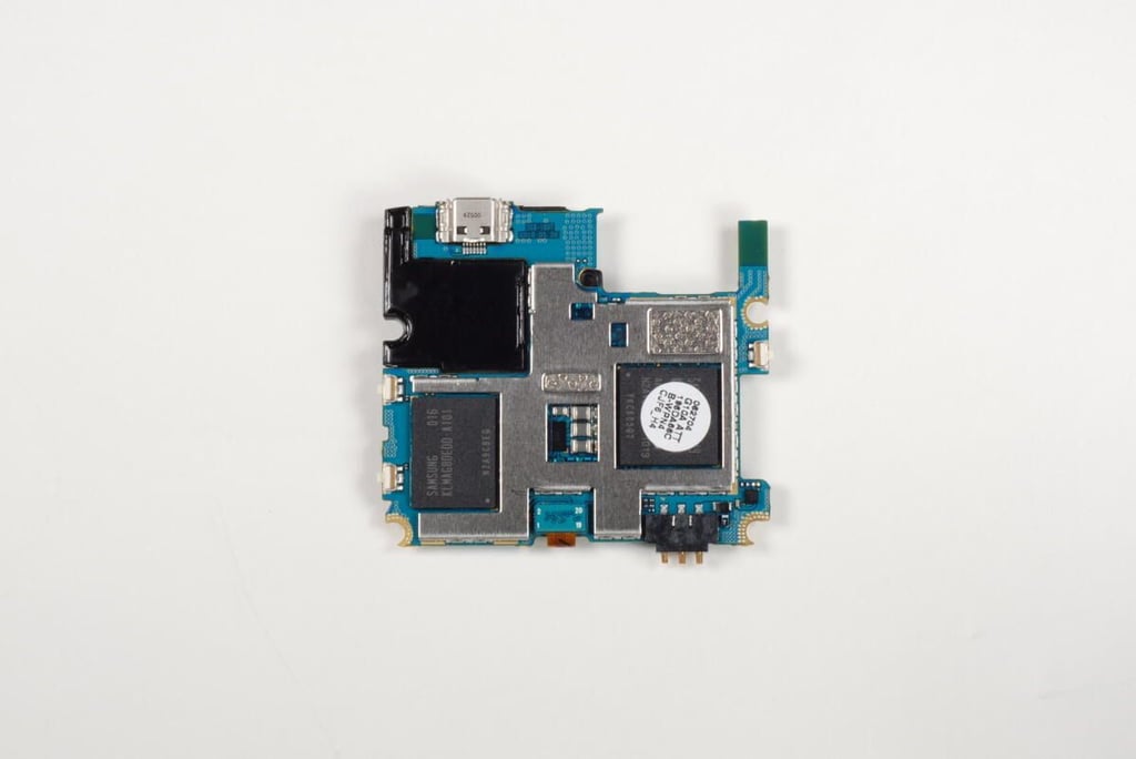
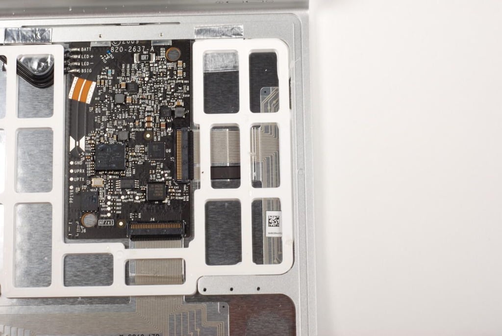
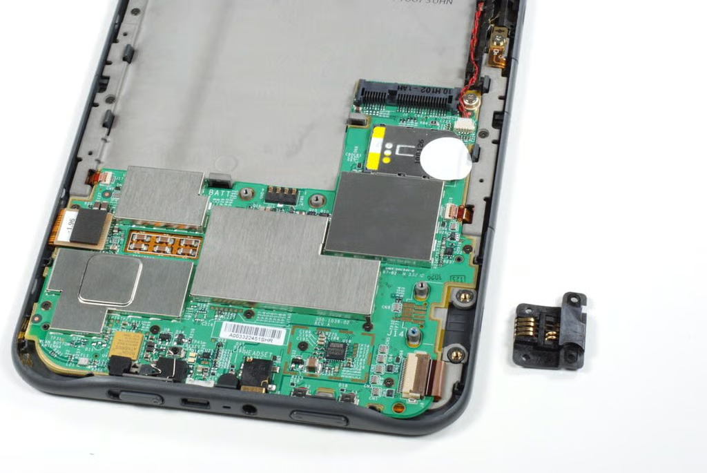
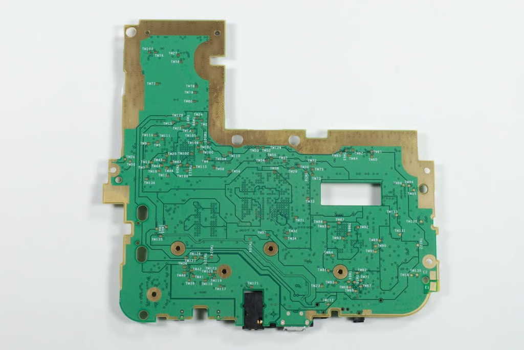
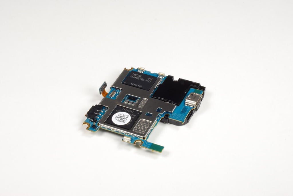
On the back of the main PCB, there are two large chips that both have Samsung markings and a connector for the SD/SIM card slot PCB.
Photo credit: Bill Detwiler / TechRepublic
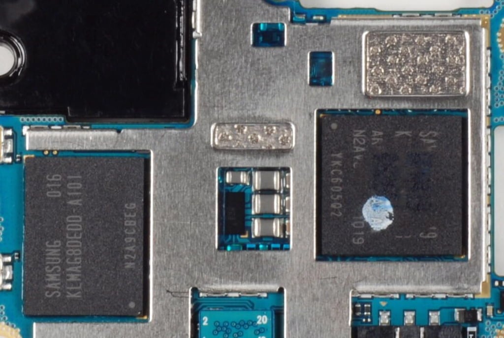
I removed the circular, white sticker from the chip on the right in this photo.
The chip on the left is the MoviNAND 16GB Flash memory chip. The chip on the right is the 1 GHz Samsung S5PC110 \u201cHummingbird\u201d (Cortex A8) processor.
Photo credit: Bill Detwiler / TechRepublic
To remove the SD/SIM card slot PCB, we must disconnect its cable from the main PCB.
Photo credit: Bill Detwiler / TechRepublic
To remove the speaker assembly, we must disconnect its ribbon cable from the SD/SIM card slot PCB. To do so, gently lift up on the tiny gate that holds the cable in the connector. You’ll also need to pry up the translucent blue tape stuck to both the connector and cable.
Photo credit: Bill Detwiler / TechRepublic
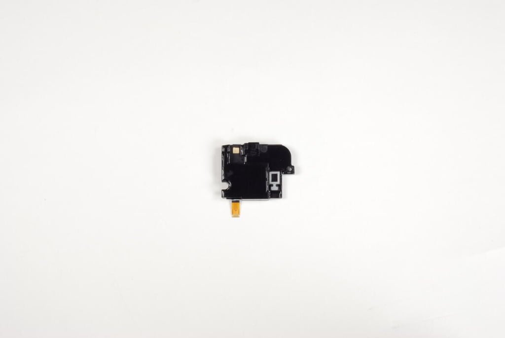
Photo credit: Bill Detwiler / TechRepublic
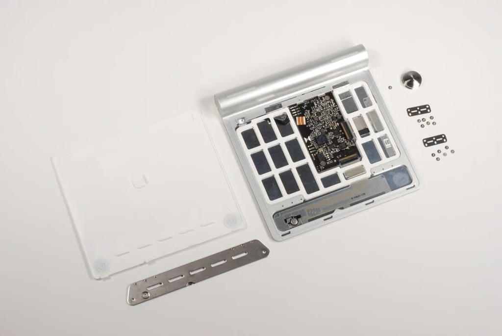
All that’s left is to remove the SD/SIM card slot PCB from the main PCB.
Photo credit: Bill Detwiler / TechRepublic
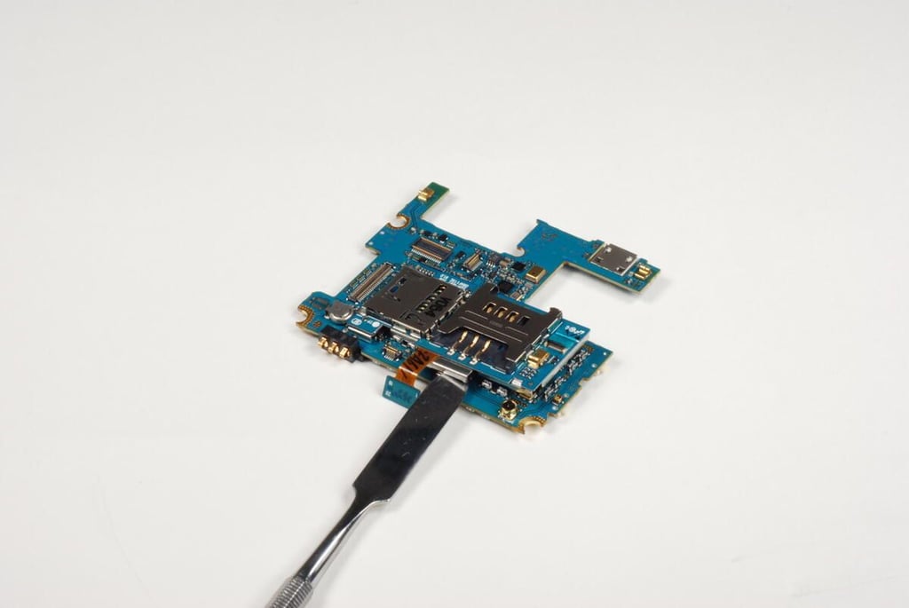
Using our thing metal spudger again, I gently pried the SD/SIM card slot PCB away from the main PCB.
Photo credit: Bill Detwiler / TechRepublic
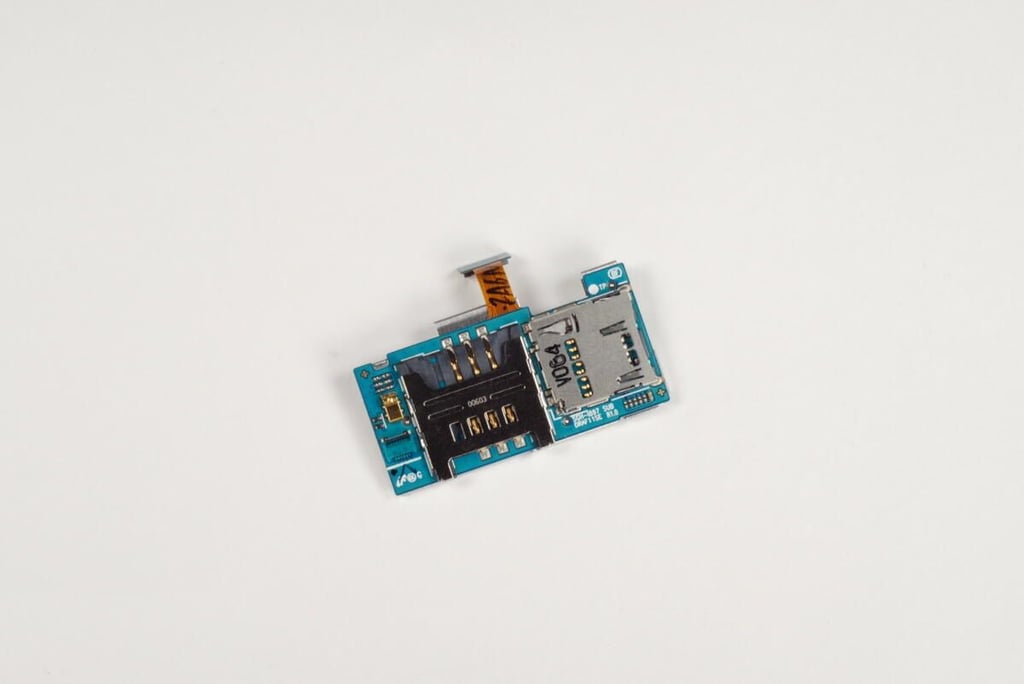
Photo credit: Bill Detwiler / TechRepublic
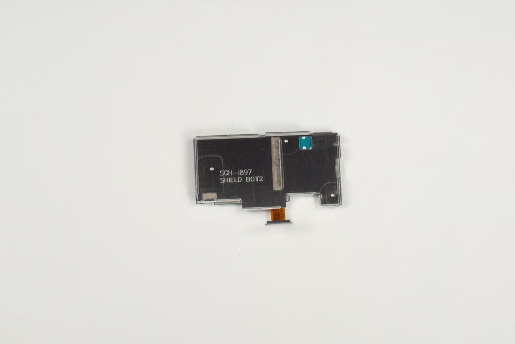
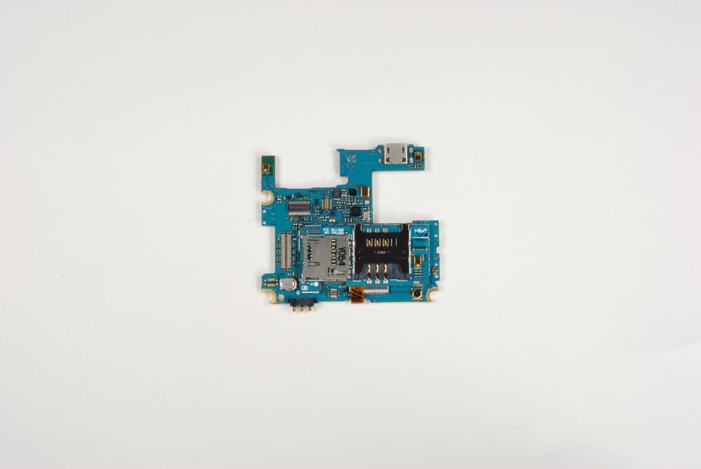
The back of the SD/SIM card slot PCB also serves as a shield for the chips located underneath it.
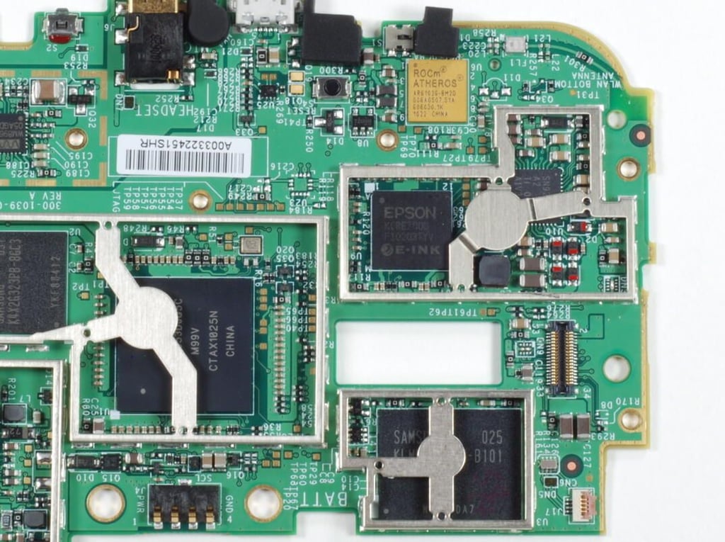
Photo credit: Bill Detwiler / TechRepublic
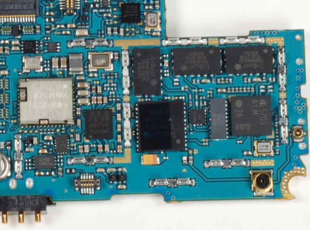
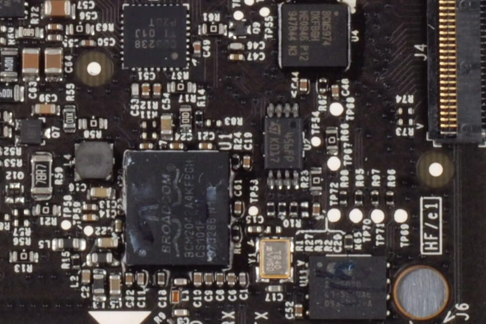
There are several TriQuint RF ICs that handle the phone’s supported frequencies:
GSM quad-band (850/900/1800/1900 MHz)
UMTS tri-band global 3G (2100/1900/850 MHz)
EDGE/UMTS/HSDPA 7.2 Mbps
The large silver chip is the Samsung SWB-B23, which provides support for Bluetooth and Wi-Fi.
Photo credit: Bill Detwiler / TechRepublic

Cracking open the Samsung Captivate wasn’t difficult, but there were a few tricky spots. If I hadn’t seen the two hidden case screws, I may have damaged the case. Also, prying the case away from the screen assembly required a gentle touch and a little patience.
Overall, the Captivate appears to be a well-constructed phone with good hardware. If you’re in the market for an Android smartphone and you already want to use AT&T, you should give it a look.
And for a more in-depth comparison of the Captivate to other Android phones, check out Jason’s Product Spotlight review.
Photo credit: Bill Detwiler / TechRepublic
Bill Detwiler is the Editor for Technical Content and Ecosystem at Celonis. He is the former Editor in Chief of TechRepublic and previous host of TechRepublic's Dynamic Developer podcast and Cracking Open, CNET and TechRepublic's popular online show. Previously, Bill was an IT manager in the social research and energy industries. He has bachelor's and master's degrees from the University of Louisville, where he has also lectured on computer crime and crime prevention.


