The Linksys EtherFast EZXS55W switch features five 10/100 auto-sensing ports with both half and full duplex modes. This model also features a dedicated Uplink port for connecting the device to other switches or similar network devices.\n\nSince each port is independently switched at up to 100 Mbps, full 200 Mbps bandwidth performance is possible when the device operates in full duplex mode. Both network cables and connected network adapters must support these higher speeds to achieve the maximum bandwidth.
Photos by Erik Eckel for TechRepublic.com
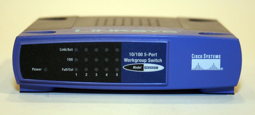
Numerous LED indicators display the desktop switch’s status. A green LED (to the bottom left) lights when the unit has power. Link, collision and 100 Mbps indicators also appear for each port.
Photos by Erik Eckel for TechRepublic.com
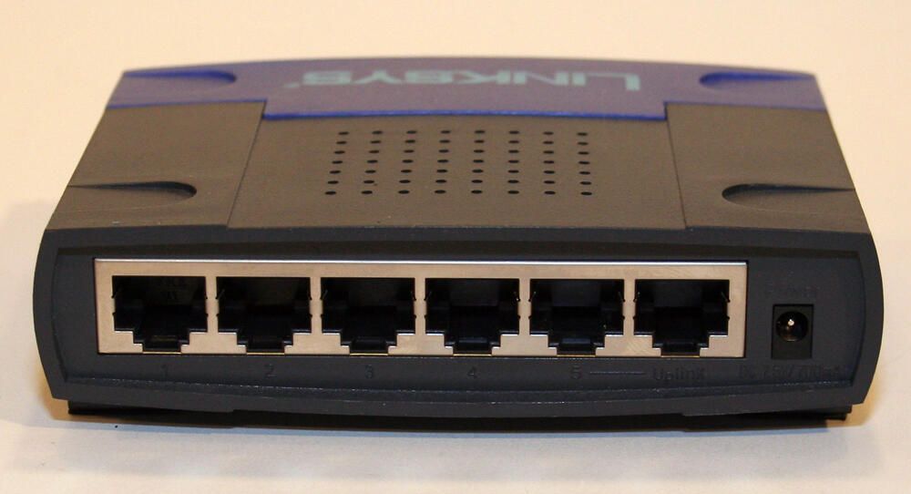
The Linksys EZXS55W includes five 10/100 ports, shown here, and an Uplink port. The unit’s power port, toward the far right, is also located on the rear panel.
Photos by Erik Eckel for TechRepublic.com
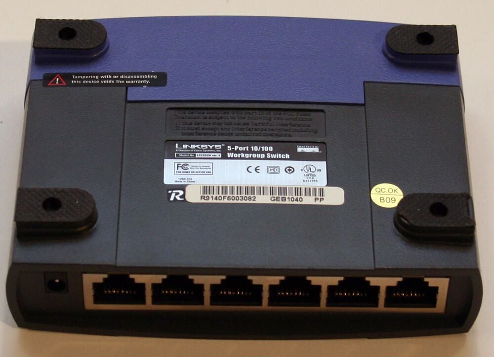
Four rubber feet help keep the desktop switch in place. That said, in my experience, zip ties or another object are often needed to keep small desktop switches in place, as the weight of four or five Ethernet cables can often pull the lightweight device out of position.
Photos by Erik Eckel for TechRepublic.com
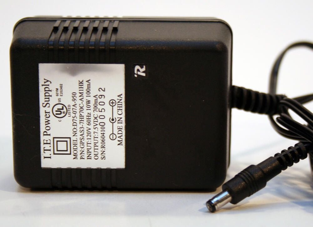
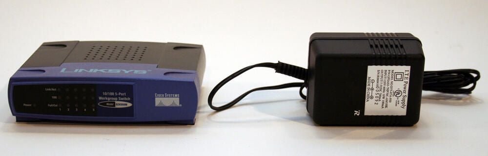
The Linksys desktop switch is powered by this ITE-manufactured power supply. This model converts AC wall electricity to 7.5-volt DC current.
Photos by Erik Eckel for TechRepublic.com
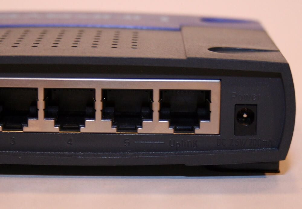
The EZXS55W’s Uplink port is the last Ethernet port on the right. When an Ethernet cable is plugged into this port, the port next door (port number 5) is disabled. This is because the Uplink port is a shared port.\n\nThe Uplink port was provided for connecting another network switch or similar device straight-through using category 5 cabling, thereby eliminating the need for a cross-over cable.
Photos by Erik Eckel for TechRepublic.com
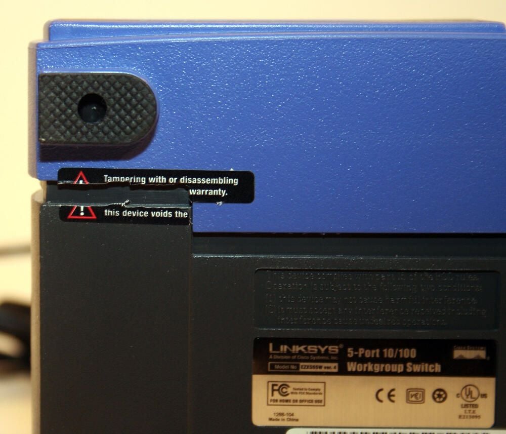
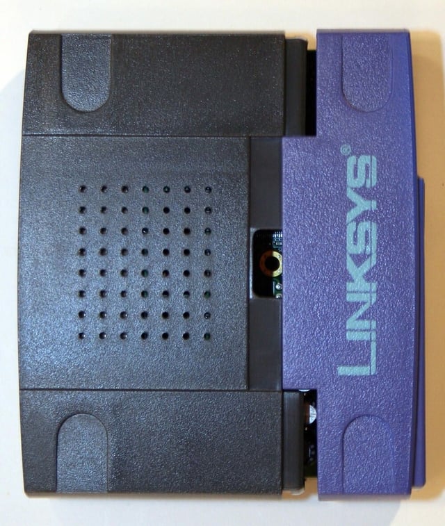
Breaking this tamper-proof tape voids the unit’s warranty. However, the action is necessary to disassemble this model.
Photos by Erik Eckel for TechRepublic.com
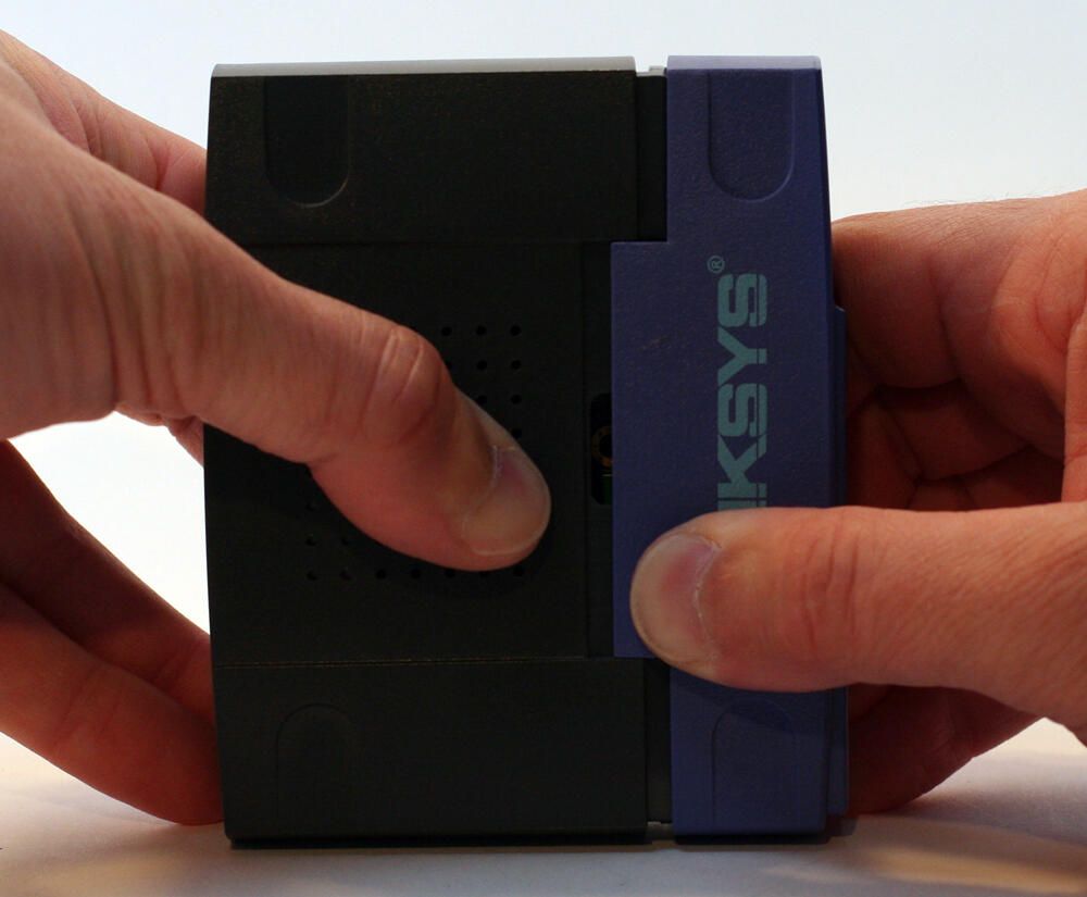
Two plastic covers, front and back pieces, compose the switch’s simple shell. To separate them, forceful pressure must be supplied where the two shells meet, as shown here.
Photos by Erik Eckel for TechRepublic.com
With the two plastic halves separated, the two shells can be pulled apart.
Photos by Erik Eckel for TechRepublic.com
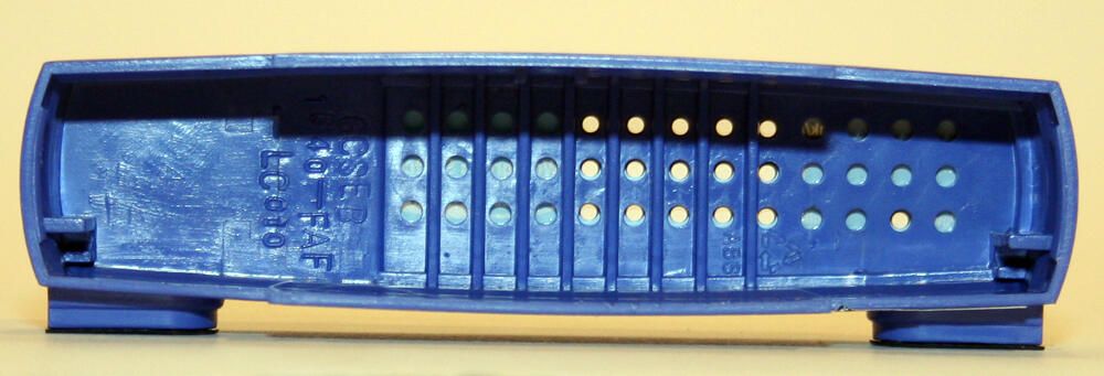
Here’s a look inside the molded plastic front cover shell. All the circular cut-outs accommodate the device’s LED status indicators.
Photos by Erik Eckel for TechRepublic.com
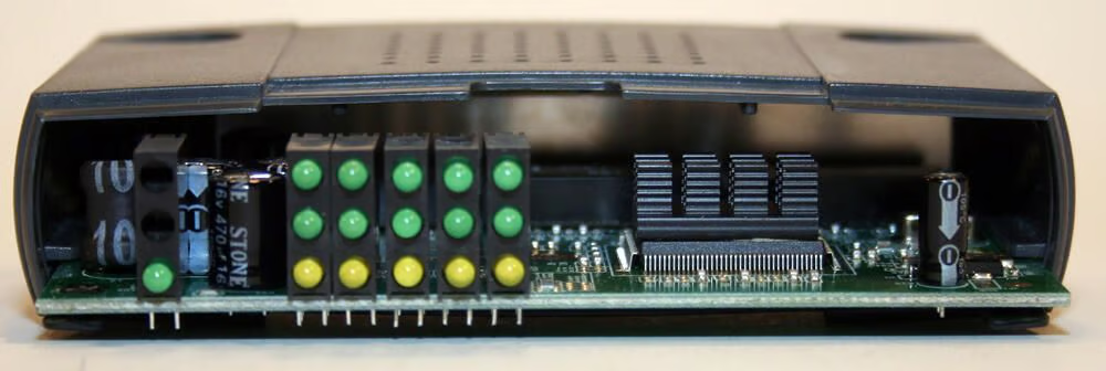
With the front cover removed, the green sysem board is visible. Prominent up front in this image are the LED status indicators. To their right you can make out the black heat sink that sits atop the device’s switch controller microchip.
Photos by Erik Eckel for TechRepublic.com
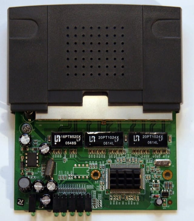
With the plastic front cover removed, the main system board slides out of the rear shell.
Photos by Erik Eckel for TechRepublic.com
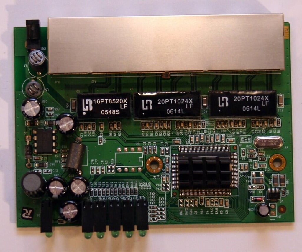
This is where all the action is. The Linksys mainboard does all the work routing network packets between ports.
Photos by Erik Eckel for TechRepublic.com
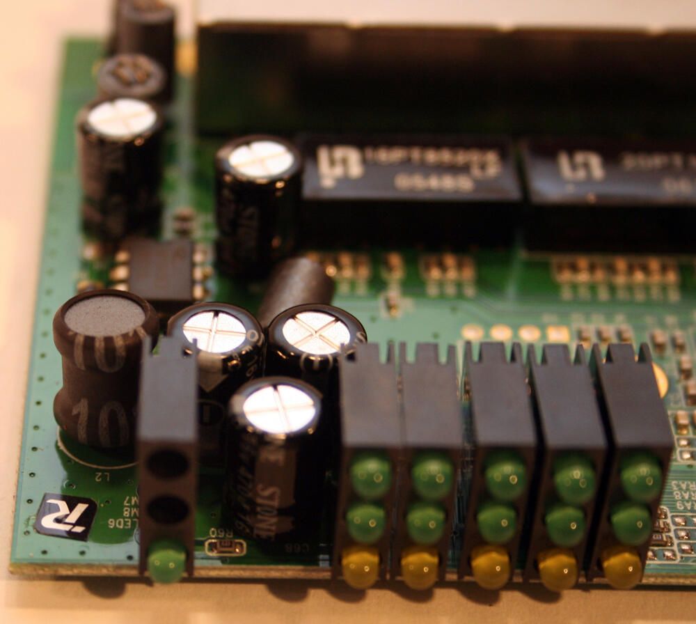
The main board relies upon several capacitors, several shown here in a close-up, to deliver bursts of energy when and where needed.
Photos by Erik Eckel for TechRepublic.com
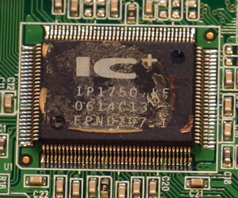
With the heat sink removed, the integrated switching chip is revealed. According to IC Plus’ technical documentation, the IP175C chip integrates switch controller, SSRAM and Ethernet transceivers, each of which complies with the IEEE 803.3, IEEE 802.3u and IEEE 802.3x specifications. The chip supports flow control, auto MDI (which helps manage uplink operations) and bandwidth control, among other functions.
Photos by Erik Eckel for TechRepublic.com
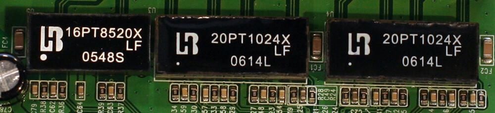
The black rectangular chip to the far left (16PT8520X) is a Bothhand USA 10/100 Base-T transformer. It helps power 10/100 Mbps data transmission.\n\nTo the right are two Bothhand USA 20PT1024X 10/100 Base-TX LAN Magnetics for Auto MDI/MDIX Application, according to the manufacturer’s data sheet. In other words, these chips help provide the switch’s autosensing network functionality.
Photos by Erik Eckel for TechRepublic.com
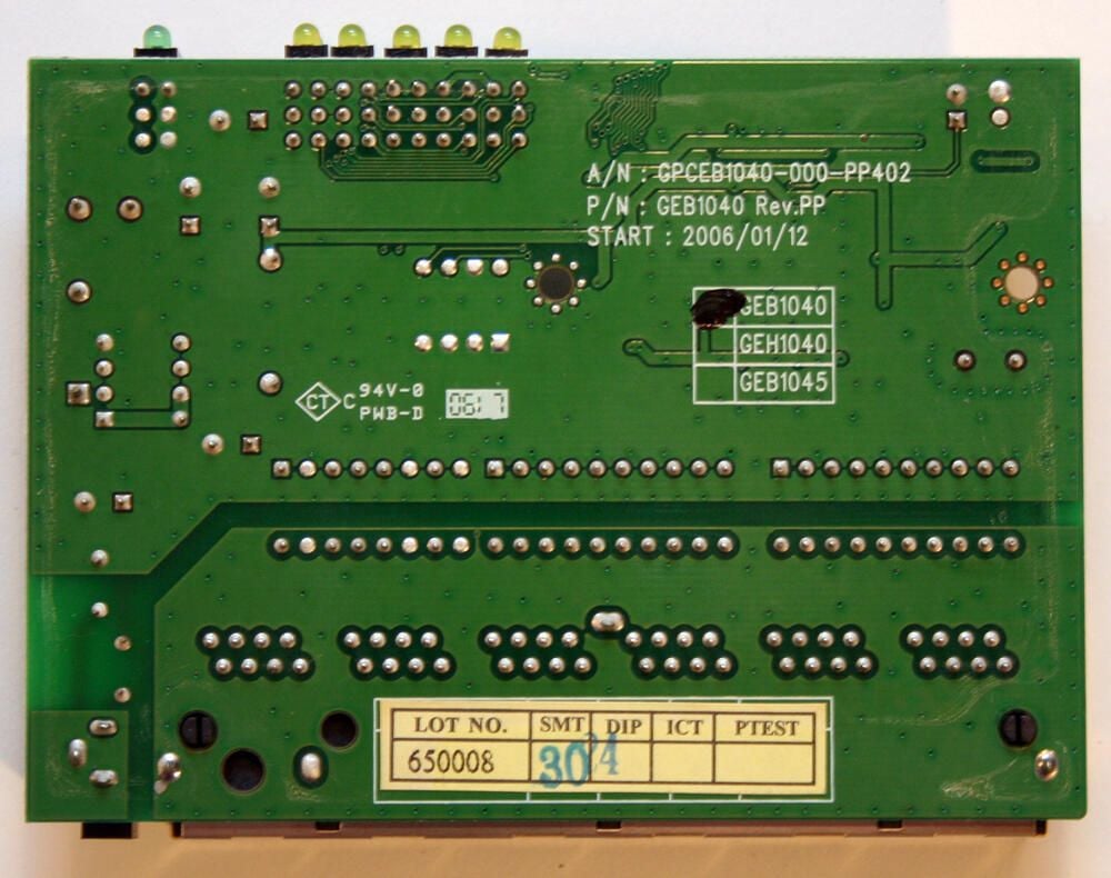
The back of the main board carries model information. This unit is model number GEB1040.
Photos by Erik Eckel for TechRepublic.com
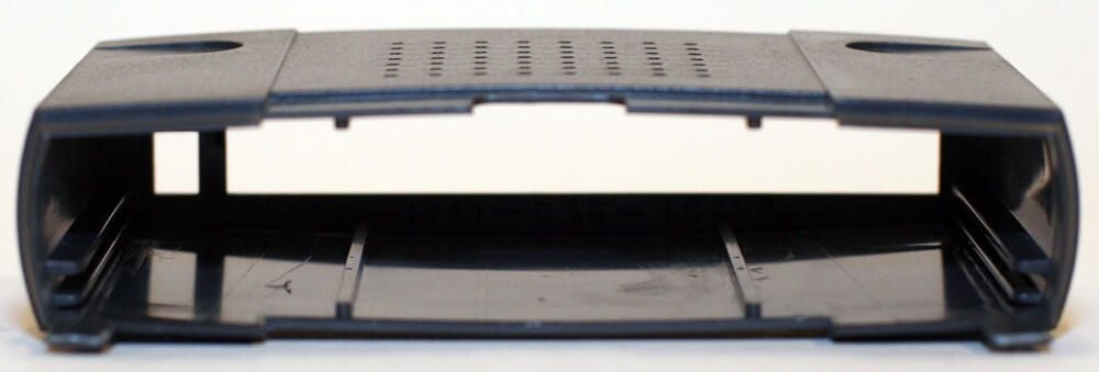
With the main board removed, the rear cover is empty. In this image you can just make out the top cover vent holes that help the unit operate within an acceptable temperature range.
Photos by Erik Eckel for TechRepublic.com
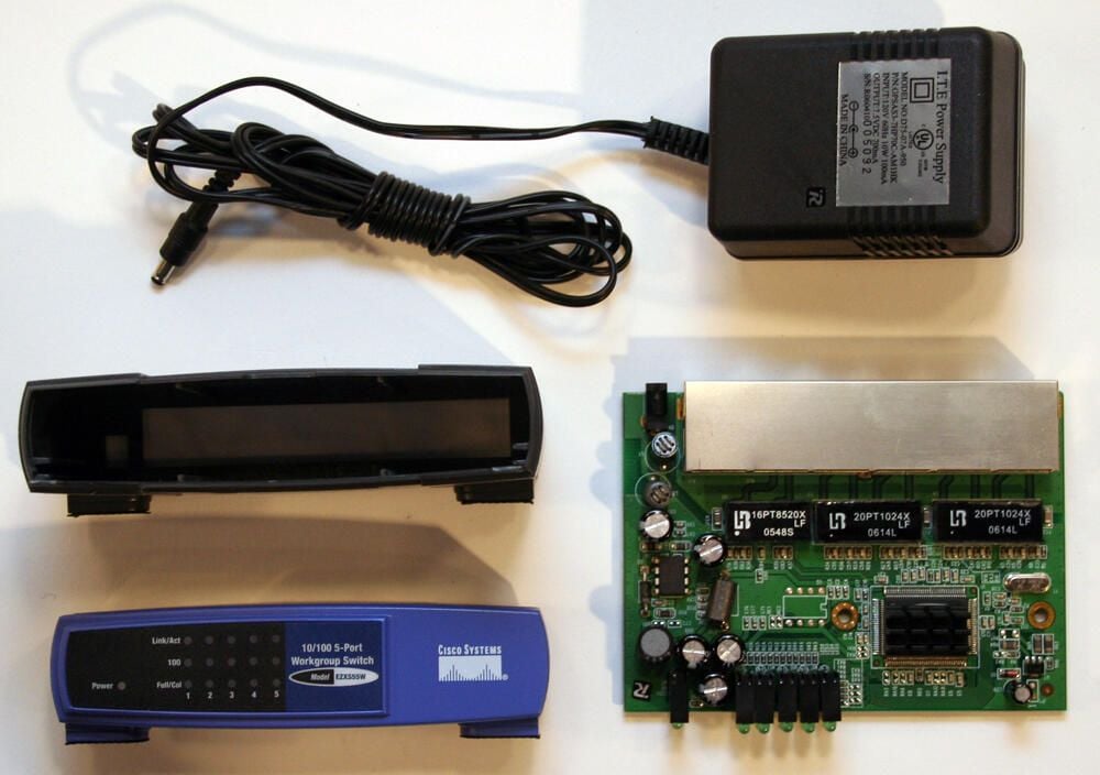
Here are all the components that compose the Linksys EtherFast EZXS55W desktop switch.
Photos by Erik Eckel for TechRepublic.com

Erik Eckel is a managing partner at Louisville Geek and president of Eckel Media Corp. He previously served as Executive Editor at TechRepublic. He received Microsoft Engineer accreditation from Sullivan University and earned his Bachelor's Degree in English from the University of Louisville. He's earned Network+, Windows NT 4.0 MCP+I and MCSE, and Windows 2000 Professional MCP accreditations.


